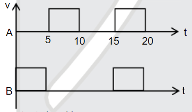
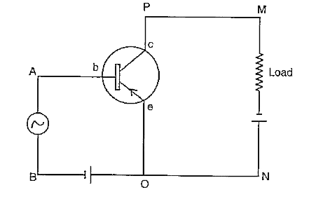
In a common base amplifier the phase difference the input signal voltage and the output voltage is
zero
π4
π2
π
The correct Answer is:A
Step by step video & image solution for In a common base amplifier the phase difference the input signal voltage and the output voltage is by Physics experts to help you in doubts & scoring excellent marks in Class 12 exams.
Updated on:21/07/2023Topper's Solved these Questions
- SEMICONDUCTOR DEVICESBOOK - AAKASH SERIESCHAPTER - SEMICONDUCTOR DEVICESEXERCISE - EXERCISE -I (LOGIC GATES)
17 Videos
- SEMICONDUCTOR DEVICESBOOK - AAKASH SERIESCHAPTER - SEMICONDUCTOR DEVICESEXERCISE - EXERCISE -I (MATCHING TYPE QUESTIONS)
9 Videos
- SEMICONDUCTOR DEVICESBOOK - AAKASH SERIESCHAPTER - SEMICONDUCTOR DEVICESEXERCISE - EXERCISE -I (P-N JUNCTION DIODE)
30 Videos
- RAY OPTICSBOOK - AAKASH SERIESCHAPTER - RAY OPTICSEXERCISE - PROBLEMS ( LEVEL-II)
60 Videos
- UNITS AND MEASUREMENTBOOK - AAKASH SERIESCHAPTER - UNITS AND MEASUREMENTEXERCISE - PRACTICE EXERCISE
45 Videos
Similar Questions
Knowledge Check
what is the output signal voltage (peak value) if dc supply voltage is 5 V?
A4 VB5 VC6 VD7 V
In a common emitter amplifier circuit using an n-p-n transistor, the phase difference between the input and the output voltages will be:-
View SolutionIn a common emitter amplifier, the input and output voltage are out of phase by
View SolutionIn a common emitter amplifier the input signal is applied across
View SolutionIn a common emitter transistor amplifier the audio signal voltage across the collector is 3V. The resistance of collector is 3kΩ. If current gain is 100 and the base resistance is 2kΩ, the voltage and power gain of the amlifier is :
View Solution
input are given as shown

then output signal is-
View SolutionFind the phase difference between voltage and current in L-C circuit.
View SolutionFigure below shows the circuit of an electronic device :

(i) Which electronic device : a rectifier, an amplifier or an oscillator does the above circuit represent?
(ii) State where the input voltage is applied and 1 where the output voltage is available.
(iii) Compare the output voltage of this circuit with its input voltage.
View Solution
