In the cicuit shown in fig. C is a parallel plate air capacitor having plate of area A=50cm2 each and distance d = 1mm apart. R1R2,andR3 are resistors having resistance 3Ω,2Ω,and1Ω respectively. Two identical sources each of emf V and of emf V and of negligible internal resistance are connected as shown in fig. if a dielectric strength of are is E0=3×10⁶Vm−10, calculate the maximum safe value of V.
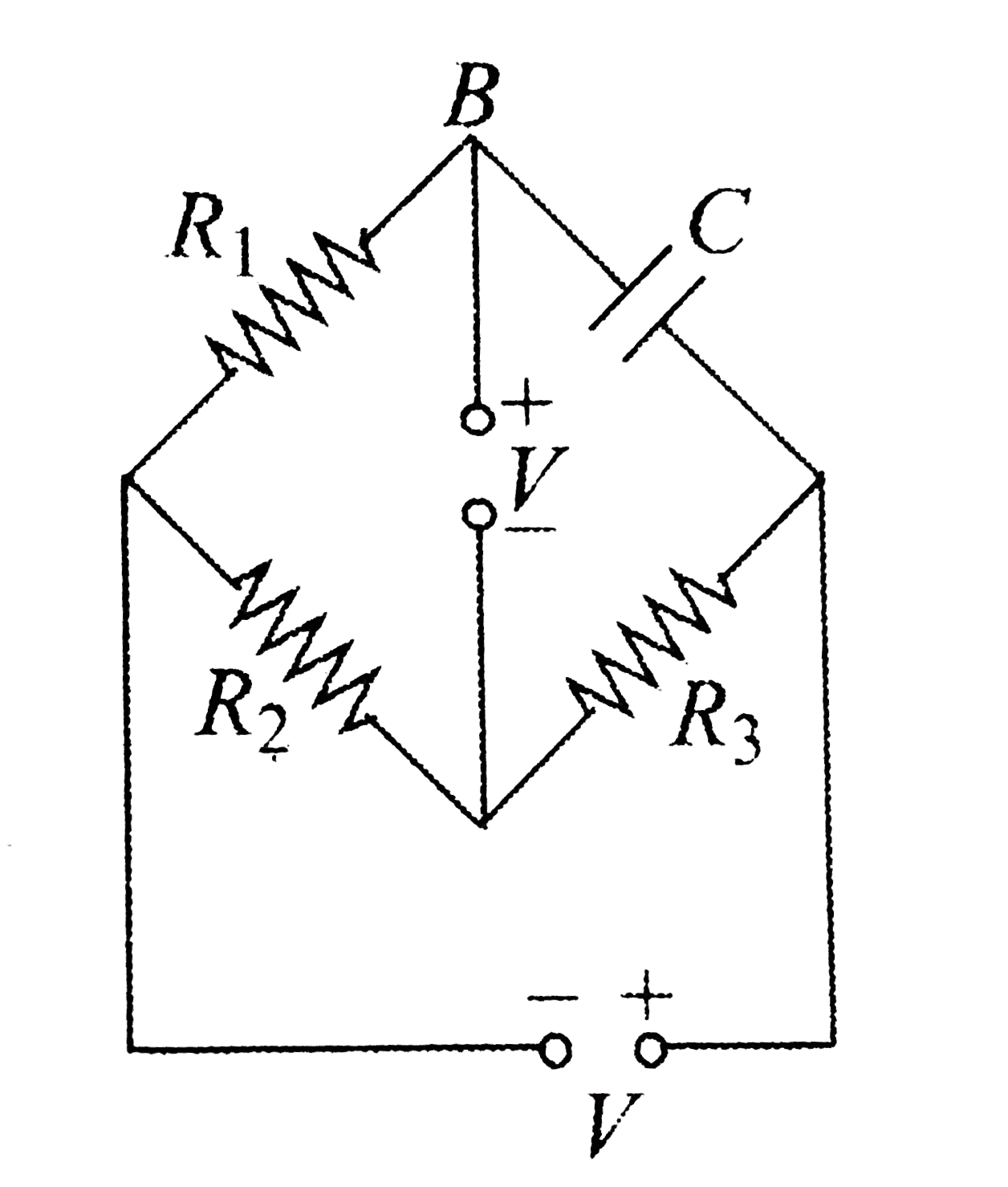
Due to sources, currents flow
through resistance R1,R2 and
R3 and capacitor gets charged.
Due to charge, an electic field
is established in the capacitor
whose magnitude cannot
exceed dielectric strength E0
of air. Maximum safe value of
V corresponds to the maximum
possible charge on capacitor.
Let the Maximum
possibel charge on capacitor be q0 then the electic field inside
the capacitor is E0=q0/Aε0,
Then the electirc field inside
the capacitor is E0=q0/Aε0,
where q0Aε0E0=15,000ε0andC=ε0A/d=5eπlon0 farad
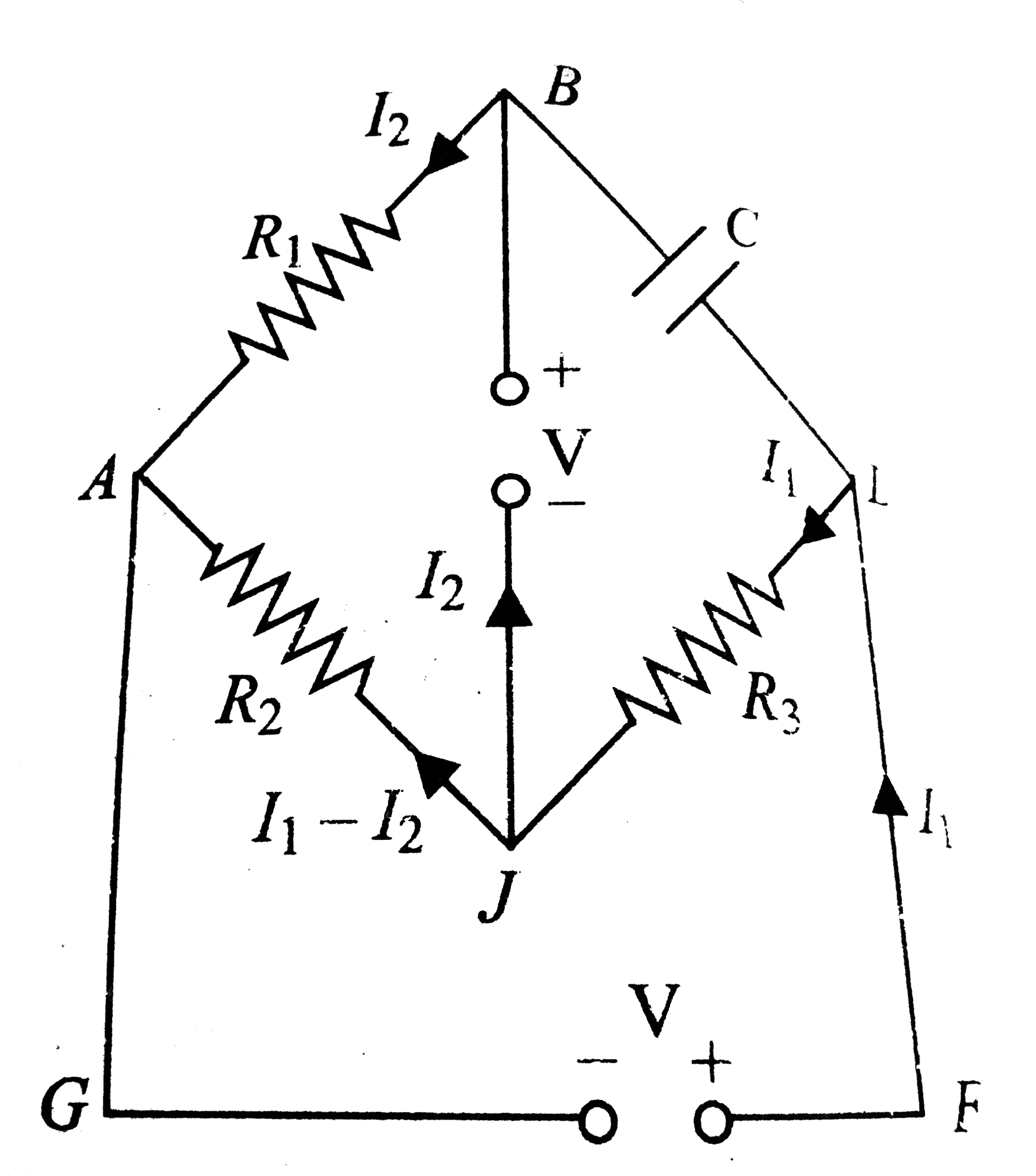 Since, in steady state, no current flows through the capacitor
current through various parts of the circuit will be as sown in
fig. Now we analyze the cirucit in a steady state. First applying Kirchhoff's voltage law on mesh ABJA, we get
I2R1+V+R2(I1−I2)=0or2I1−5I2=−V (i)
For mesh AJDFGA,
−R2(I1−I2)−R3I1+V=0oreI1−2I2=V (ii)
From Eqs. (i) and (ii): I1=7V11 and I2=%V11
Now applying Kirchhoff's voltage law on mesh BDJB, we get
qC+I1R3−V=0ororq=4CV11=2011ε0V
But the maximum possible value of q is q0=15,000ε0. Therefore, the maximum safe value of V is 11q0/20ε0=8250V=8.25kV.
Topper's Solved these Questions
- ELECTRIC CURRENT AND CIRCUITBOOK - CENGAGE PHYSICS ENGLISHCHAPTER - ELECTRIC CURRENT AND CIRCUITEXERCISE - Single Correct
72 Videos
- ELECTRIC CURRENT AND CIRCUITBOOK - CENGAGE PHYSICS ENGLISHCHAPTER - ELECTRIC CURRENT AND CIRCUITEXERCISE - Multiple Correct
16 Videos
- ELECTRIC CURRENT AND CIRCUITBOOK - CENGAGE PHYSICS ENGLISHCHAPTER - ELECTRIC CURRENT AND CIRCUITEXERCISE - Exercise 5.2
50 Videos
- ELECTRIC CURRENT & CIRCUITSBOOK - CENGAGE PHYSICS ENGLISHCHAPTER - ELECTRIC CURRENT & CIRCUITSEXERCISE - Kirchhoff s law and simple circuits
15 Videos
- ELECTRIC FLUX AND GAUSS LAWBOOK - CENGAGE PHYSICS ENGLISHCHAPTER - ELECTRIC FLUX AND GAUSS LAWEXERCISE - MCQ s
38 Videos
Similar Questions
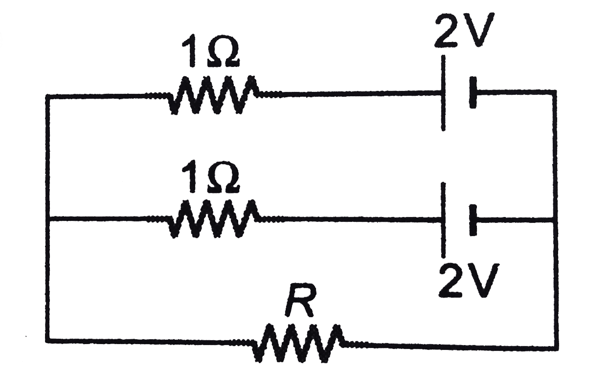
Two indentical batteries, each of emf 2V andinternal resistance r=1Ω are connected as shown. The maximum power that can be developed across R using these batteries is
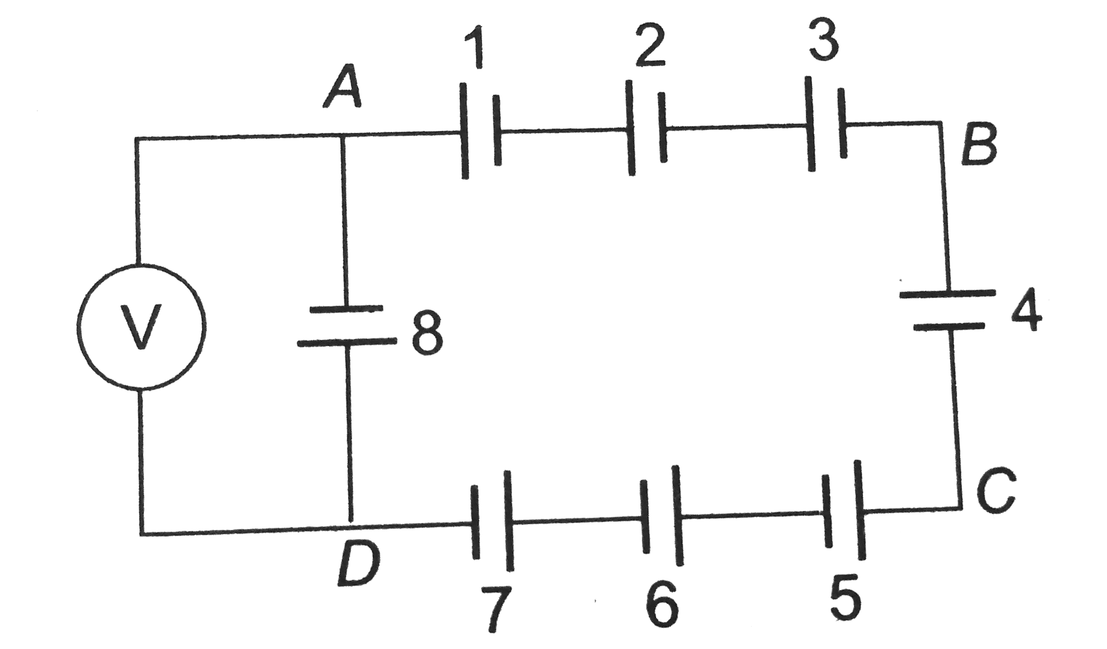
View SolutionEight cells marked 1 to 8, each of emf 5V and internal resistance 0.2Ω are connected as shown. What is the reading of ideal voltmeter ?
View Solution
Knowledge Check
Three resistors of resistances 3Ω,4Ωand5Ω are combined in parallel. This combination is connected to a battery of emf 12V and negligible internal resistance, current through each resistor in ampere is
A4,3,2.4B8,7,3,4C2,5,1,8D5,5,8,2
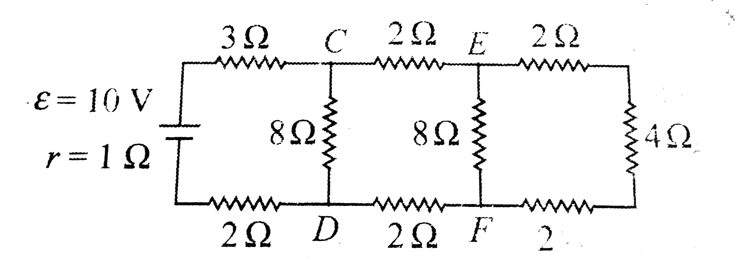
In the circuit shown in fig. the cell has emf 10V and internal resistance 1Ω
View SolutionTwo resistors of resistances 2Ω and 6Ω are connected in parallel. This combination is then connected to a battery of emf 2 V and internal resistance 0.5Ω. What is the current flowing through the battery ?
View Solution24 cells, each of emf 1.5V and internal resistance is 2Ω connected to 12Ω series external resistance. Then,
View SolutionIn the circuit shown E,F,G and H are cells of emf 2V,1V,3V and 1V respectively and their internal resistance are 2Ω,1Ω,3Ω and 1Ω respectively.
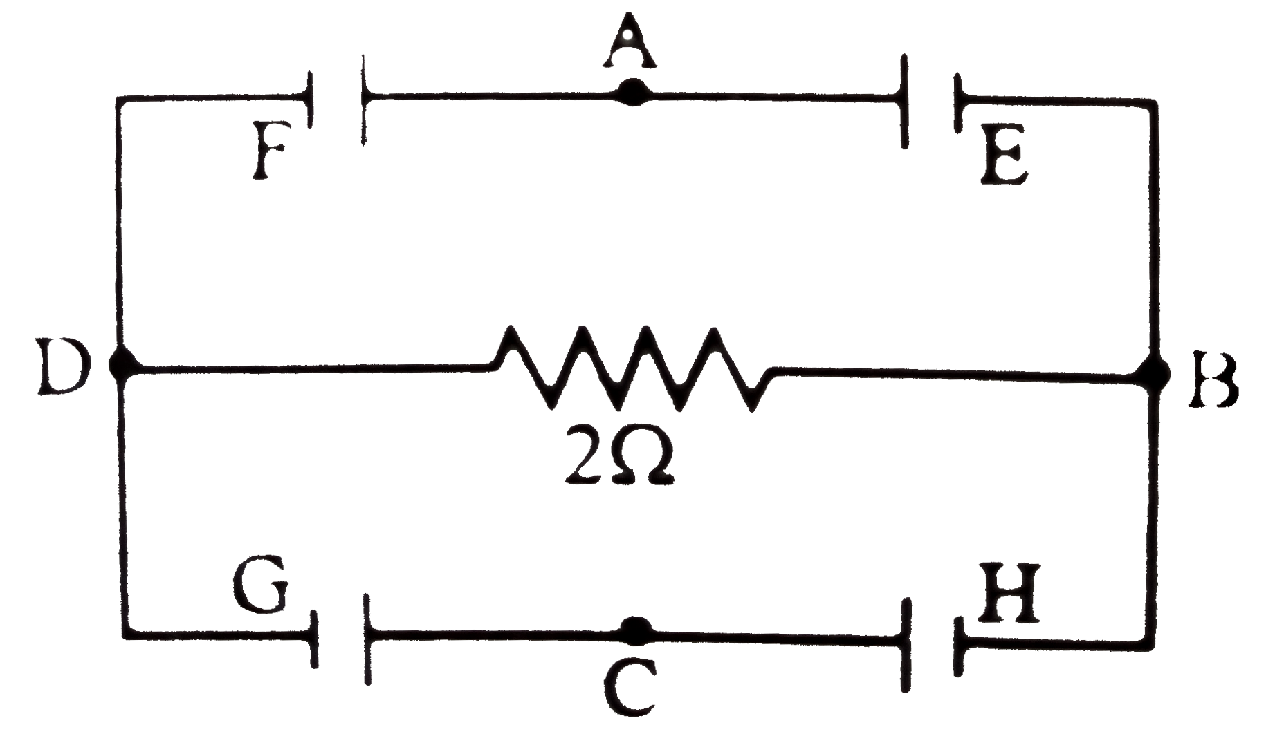
View SolutionIn the circuit shown E,F,G and H are cells of emf 2V,1V,3V and 1V respectively and their internal resistance are 2Ω,1Ω,3Ω and 1Ω respectively.

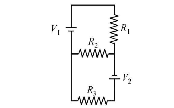
View SolutionTwo ideal batteries of emf V1andV2 and three resistances R1,R2andR3 are connected as shown in the figure. The current in resistance R2 would be zero if
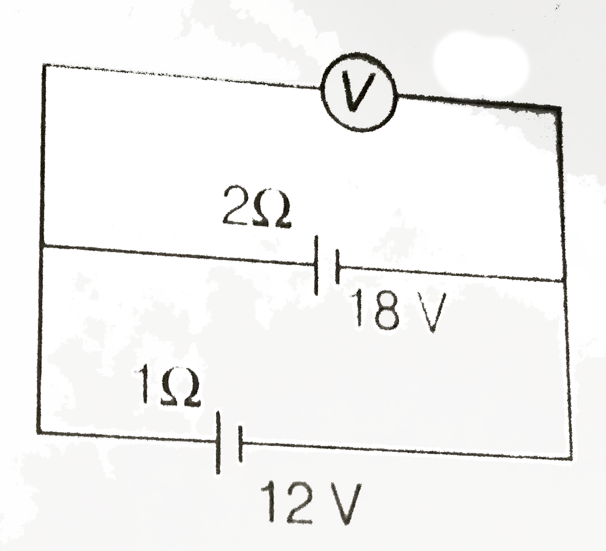
View SolutionTwo batteries, one of emf 18V and internal resistance 2Ω and the other of emf 12 and internal resistance 1Ω , are connected as shown. The voltmeter V will record a reading of
View Solution
