In the circuit shown, A and V are ideal ammeter and voltmeter respectively. Reading of the voltmeter will be

2V
1V
0.5V
Zero
The correct Answer is:D
Step by step video, text & image solution for In the circuit shown, A and V are ideal ammeter and voltmeter respectively. Reading of the voltmeter will be by Physics experts to help you in doubts & scoring excellent marks in Class 12 exams.
Topper's Solved these Questions
- BOOK - DC PANDEYCHAPTER - CURRENT ELECTRICITYEXERCISE - Taking it together142videos
CURRENT ELECTRICITY
- BOOK - DC PANDEYCHAPTER - CURRENT ELECTRICITYEXERCISE - B. Assertion and reason18videos
CURRENT ELECTRICITY
- BOOK - DC PANDEYCHAPTER - CURRENT ELECTRICITYEXERCISE - Example61videos
CURRENT ELECTRICITY
- BOOK - DC PANDEYCHAPTER - COMMUNICATION SYSTEMEXERCISE - Subjective11videos
COMMUNICATION SYSTEM
- BOOK - DC PANDEYCHAPTER - ELECTROMAGNETIC INDUCTIONEXERCISE - Medical entrances gallery25videos
ELECTROMAGNETIC INDUCTION
Similar Questions
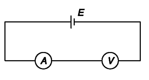
In the circuit shown, an ideal cell of emf E is connected in series to a non-ideal ammeter and voltmeter. Reading of the voltmeter is V0. When a resistance is added in parallel to the voltmeter its reading becomes V010 and the reading of the ammeter becomes 10 times the earlier value. find V0 in terms of E.
 View Solution
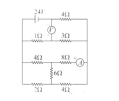
In the circuit shown, the battery, the ammeter and the voltmeter are ideal. Pick the correct choice(s) :
 View Solution
Knowledge Check
- Question 1 - Select One
In the circuit shown here, the readings of the ammeter and voltmeter are
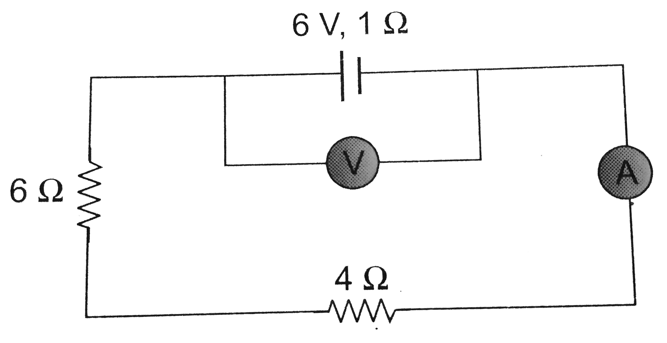 A6A,60VB0.6A,6VC6/11A,60/11VD11/6A,11/60V
 - Question 2 - Select One
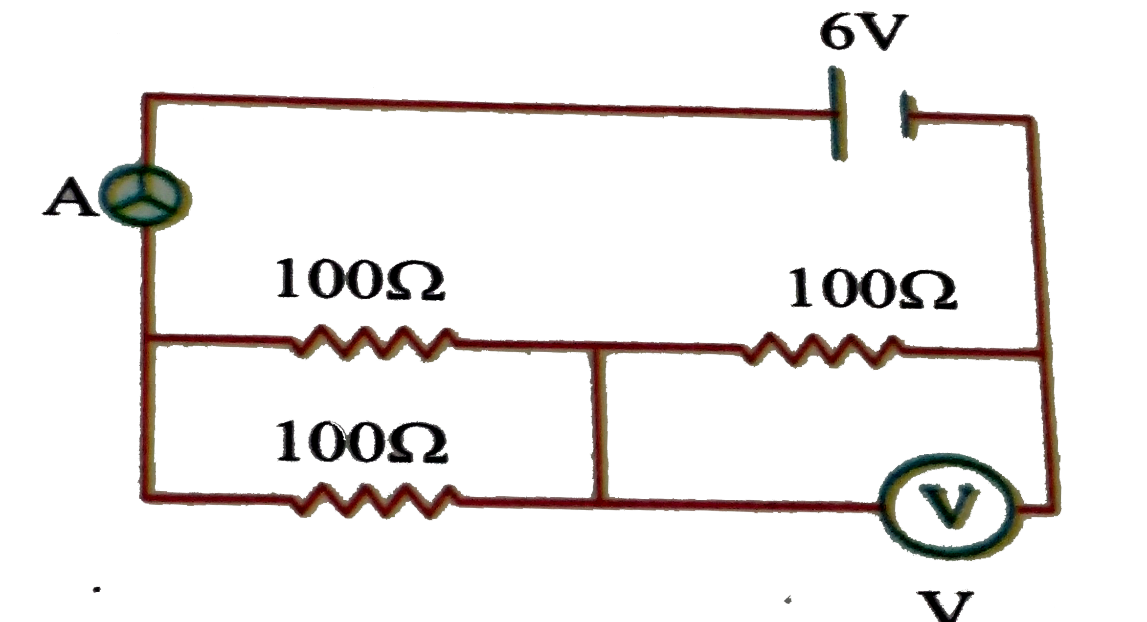
In the circuit shown, the reading of the voltmeter and the ammeter areA4V.0.2AB2V,0.4AC3V,0.6AD4V,0.04A - Question 3 - Select One

Assertion : In the circuit shown in figure ammeter and voltmeter are non-ideal. Why positions of ammeter and voltmeter are changed, reading of ammeter will increase while of voltmeter will decrease.
Reason : Resistance of an ideal ammeter is zero while that of an ideal voltmeter is infinite.AIf both Assertion and Reason are true and the Reason is correct explanation of the Assertion.BIf both Assertion and Reason are true but Reason is not the correct explanation of Assertion.CIf Assertion is true, but the Reason is false.DIf Assertion is false but the Reason is true.
In the circuit shown below. The reading of the voltmeter V is
 View Solution
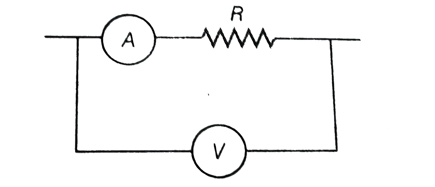
In the circuit shown below, the ammeter and the voltmeter readings are 3 A and 6 V respectively . Then, the value of the resistance R is
 View Solution
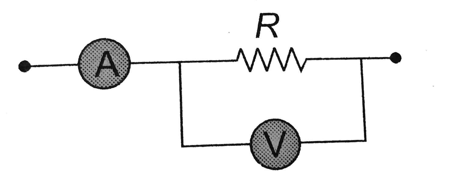
In the circuit shown the reading of ammeter and voltmeter are 4A and 20V respectively. The meters are non ideal, then R ia
 View Solution
In the circuit shown in Fig. 6.50, an idel ammeter and an ideal voltmeter are used. Whan the key is open, the voltmeter reads 1.53V. When the key is closed, the ammeter reads 1.0A and the voltmeter reads 1.03V. The resistance R is
 View Solution
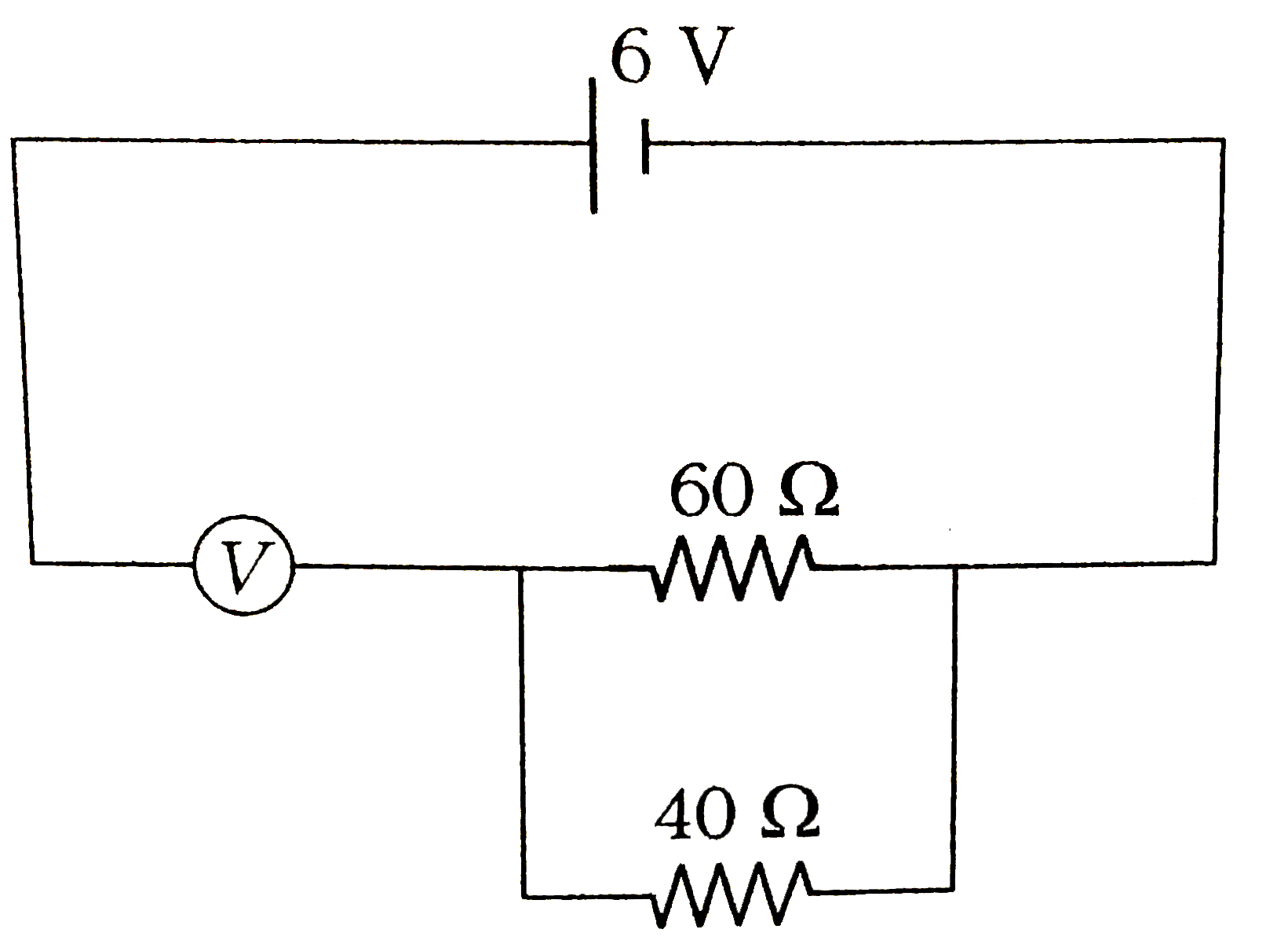
In the circuit shown in the figure, the voltmeter reading is
 View Solution

