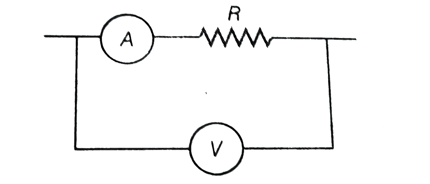
In the circuit shown, the battery, the ammeter and the voltmeter are ideal. Pick the correct choice(s) :
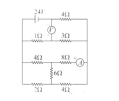
A
Power supplied by battery is 72 W
B
Rate of heat dissipation in 3Ω resistance is 12 W
C
The ammeter reads 43A
D
The voltmeter reads 22 V
Video Solution
Text Solution
The lower network of 4-8-6-2-4 is a wheat stone bridge in balanced condition since So, we remove . Now, net resistance in series with battery is 6Ω
⇒ Current through battery=4V
So, current in the three branches, starting from the top are 2A,23A,43A
⇒ Ammeter reads 23A, Voltmeter reading =24-(L) (2)
⇒ Power supplied =24×4=96W⇒ Dissipation in 3Ω=22×3=12W
|
Updated on:21/07/2023
Similar Questions
Knowledge Check
- Question 1 - Select One
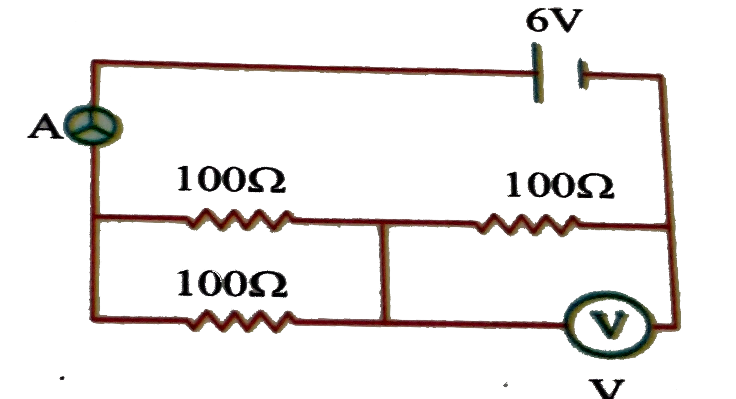
In the circuit shown, the reading of the voltmeter and the ammeter areA4V.0.2AB2V,0.4AC3V,0.6AD4V,0.04A - Question 2 - Select One
In the circuit shown here, the readings of the ammeter and voltmeter are
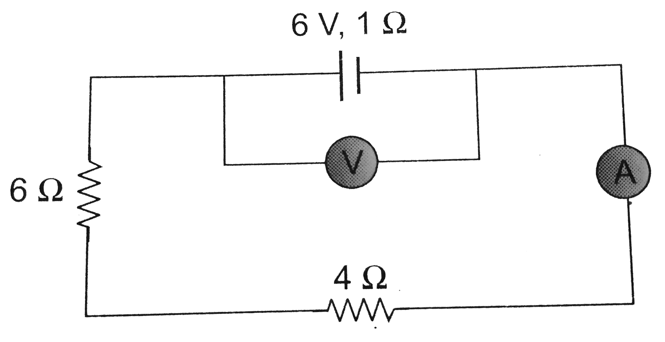 A6A,60VB0.6A,6VC6/11A,60/11VD11/6A,11/60V
 - Question 3 - Select One or More
In the circuit shown, battery, ammeter , and voltmeter are ideal and the switch S is initially closed as shown. When switch S is opened
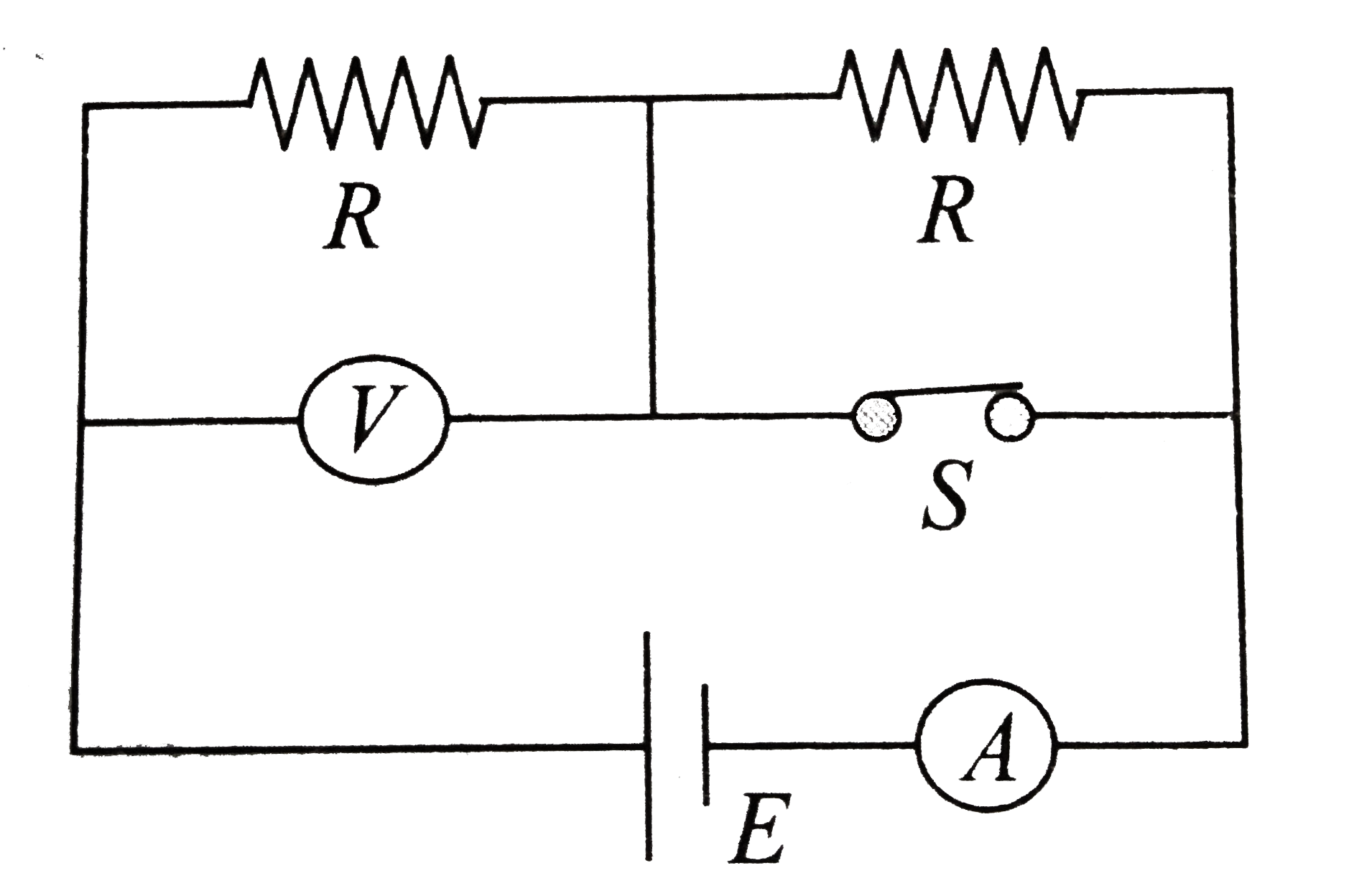 Aequivalent resistance across the battery increasesBpower dissipated by left resistance R increasesCvoltmeter reading decreasesDammeter reading decreases.
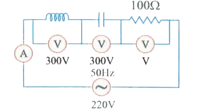
In the circuit shown below what will be the reading of the voltmeters and ammeter?
 View Solution
In the circuit shown below, the ammeter A reads 5 A and the voltmeter V reads 20 V The correct value of resistance R is
 View Solution
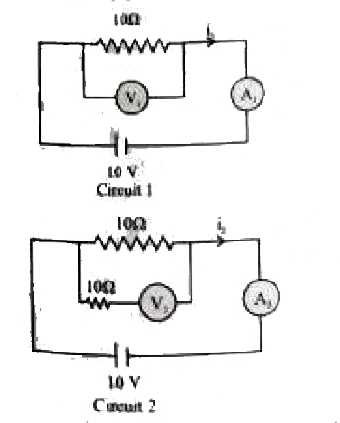
In the circuits shown below, the readings of the voltmeters and the ammeters will be
 View Solution
In the circuit shown, the reading of the ammeter if diode is not ideal, will be
 View Solution
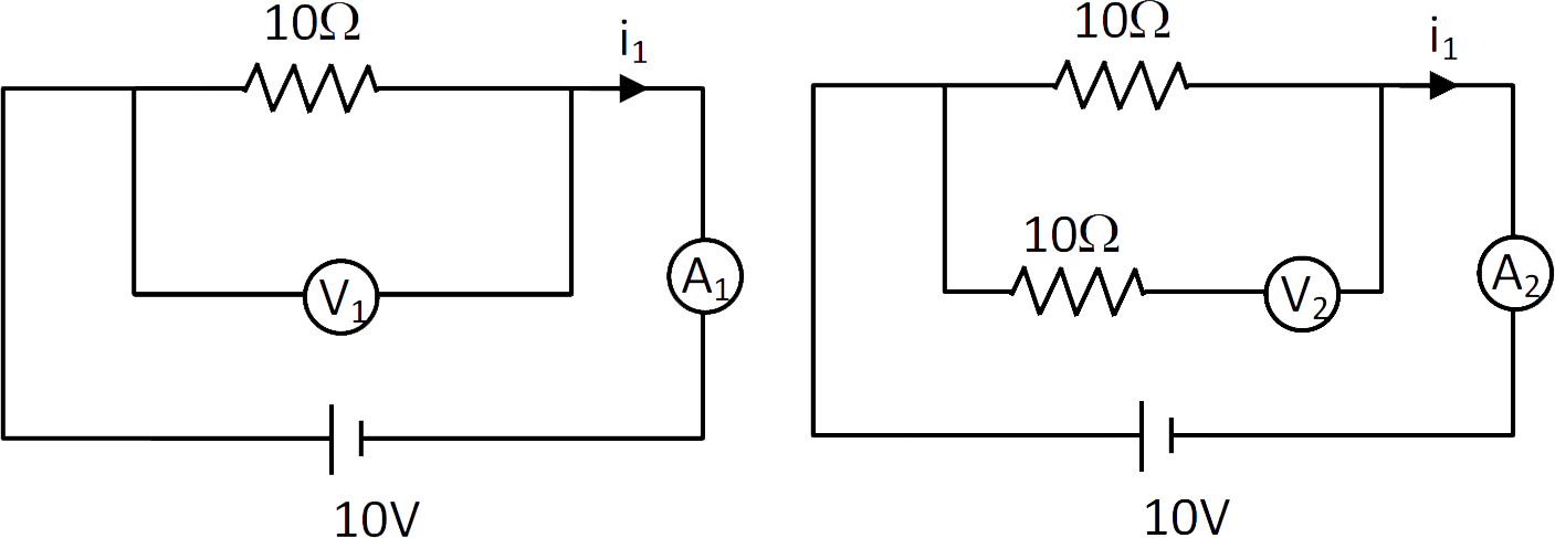
In the circuits shown below, the readings of the voltmeters and the ammeters will be:
 View Solution

