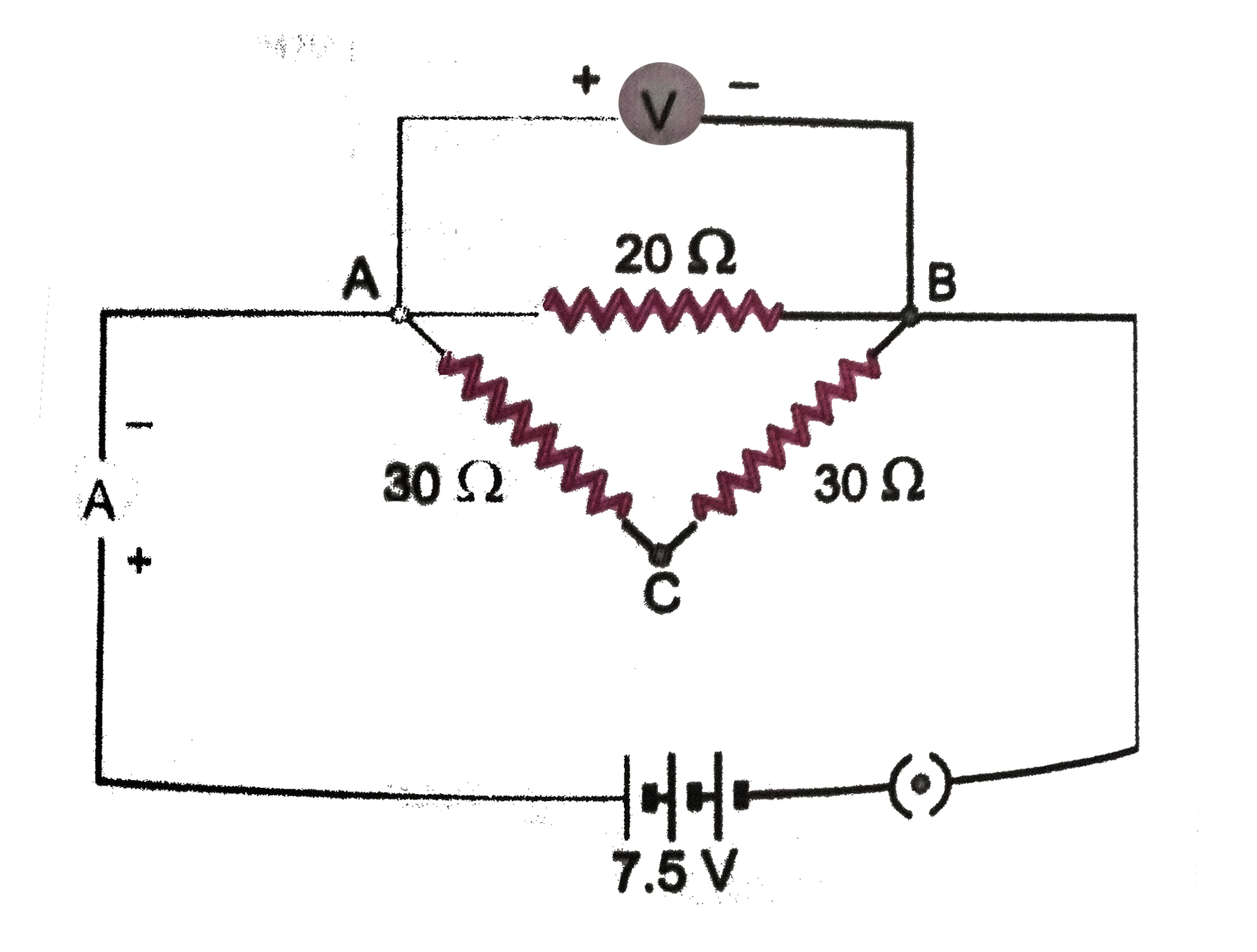
In the circuit shown in (fig. 3.51), find the current recorded by ammeter (A).
 .
.
Since resistance, AC=30Ω and resistances CB=30Ω,
resistance in the path ACB=30Ω+30Ω=60Ω.
Further, 60Ω (in the path ACB) and 20Ω (in the path AB) are in parallel, effective resistance between AandB is given
by 1R=160+120=1+360=460=115 or R=15Ω
Current, I=7.5V15Ω=0.5A.
Topper's Solved these Questions
- ELECTRICITYBOOK - PRADEEPCHAPTER - ELECTRICITYEXERCISE - Higher Order Thinking
7 Videos
- ELECTRICITYBOOK - PRADEEPCHAPTER - ELECTRICITYEXERCISE - Value Based Question
4 Videos
- ELECTRICITYBOOK - PRADEEPCHAPTER - ELECTRICITYEXERCISE - (Additional)Long Answer
4 Videos
- MAGNETIC EFFECTS OF ELECTRIC CURRENTBOOK - PRADEEPCHAPTER - MAGNETIC EFFECTS OF ELECTRIC CURRENTEXERCISE - Mock Test
21 Videos
Similar Questions
Knowledge Check
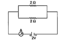
In a circuit shown in figure, the current recorded by an ideal ammeter A is
 A2AB1AC0.5AD0.25A
In the circuit shown in fig. find the current through the branch BD.
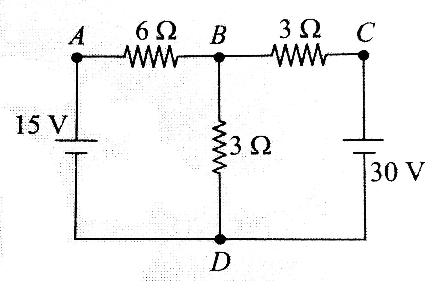 A2 AB3 AC4 AD5 A
In the circuit shown in the figure, find the current in 45Ω
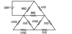 A4AB2.5 AC2ADNone of these
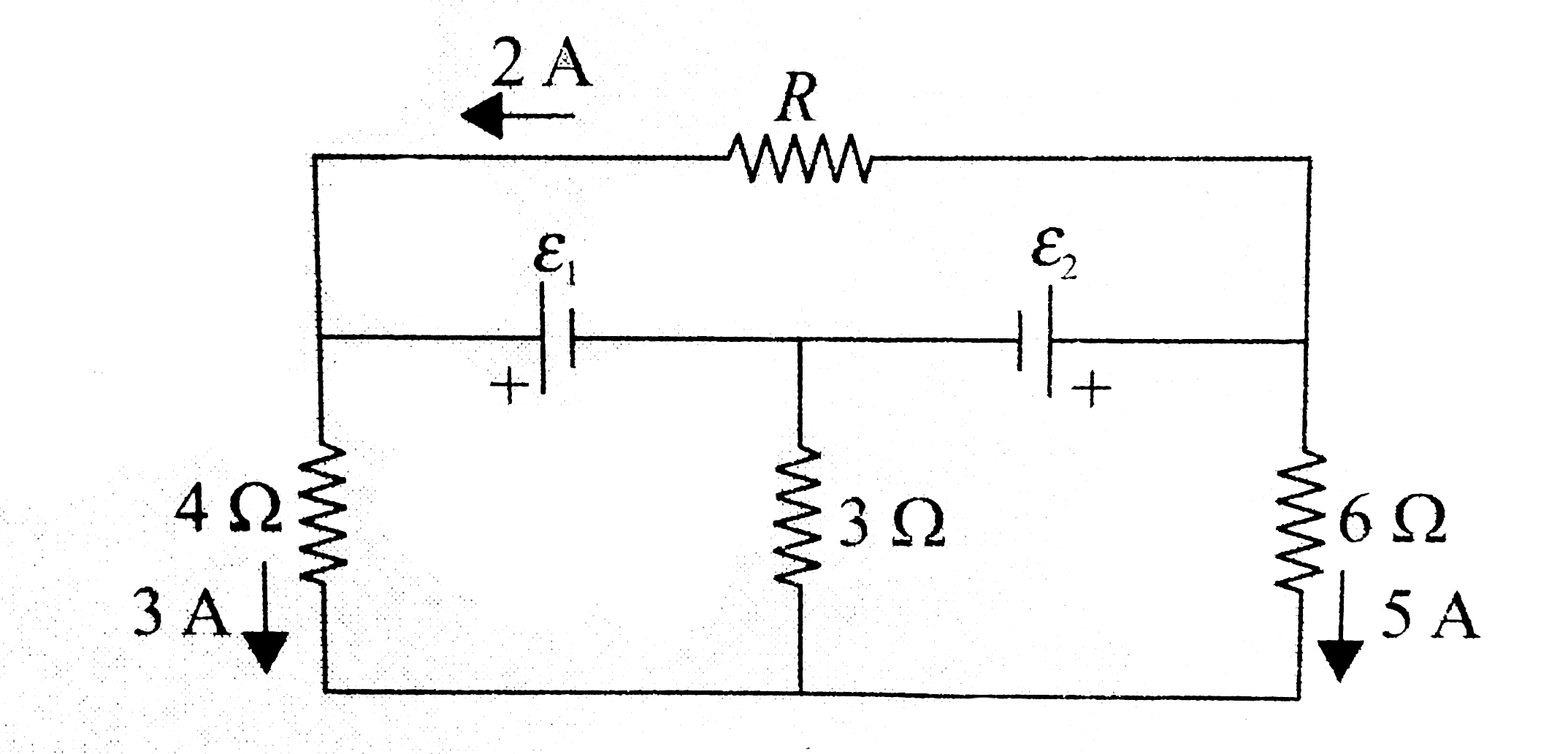
In the circuit shown in fig
a. find the current in resistor R
b. find the reistor R
c. find the the unkown emf ε
d. if the circuit is broken at point x,
what is the current in resistor R ?
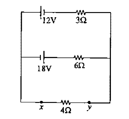
View SolutionIn the circuit shown in figure-3.171, find current in 4Ω resistance.
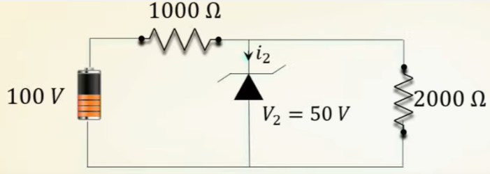
View SolutionIn the circuit shown,find the current through the Zener diode.
View SolutionPlot the vector diagram for currents in the circuit shown in Fig. 36.11 a and find the current in the unbranched section of the circuit. What is the condition for the current in the unbranched section of be a minimum? What is the phase shift between the voltage and the current in general, and at resonance?

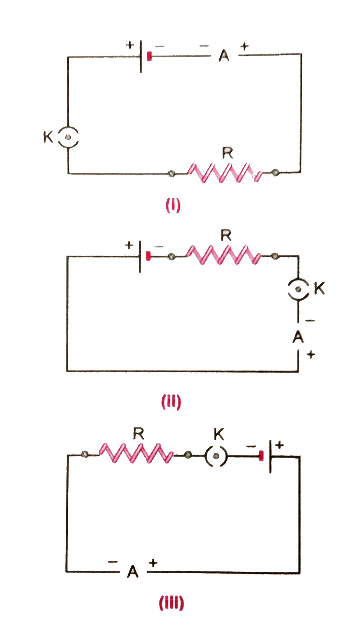
View SolutionA cell, a resistor, a key and an ammeter are arranged as shown in the circuit diagrams of (Fig. 3.37). The current recorded in the ammeter will be :
View Solution

