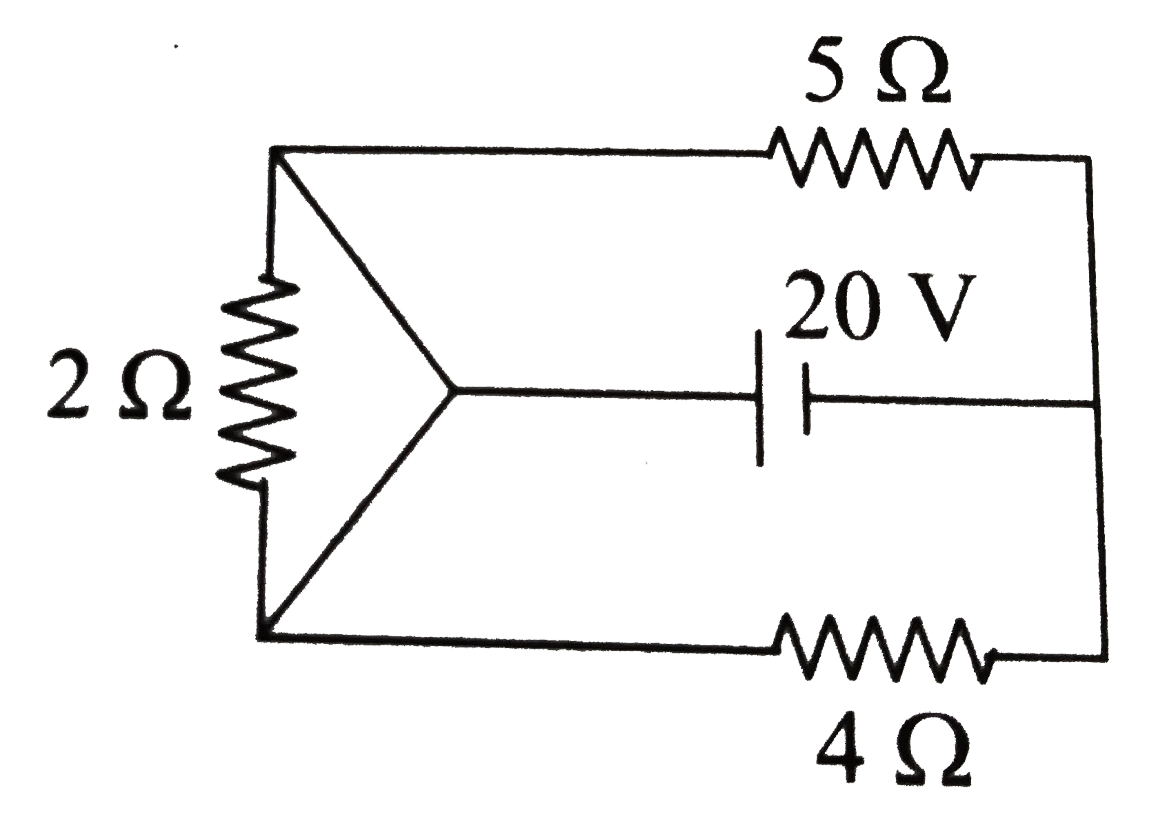
In the circuit shown in figure,
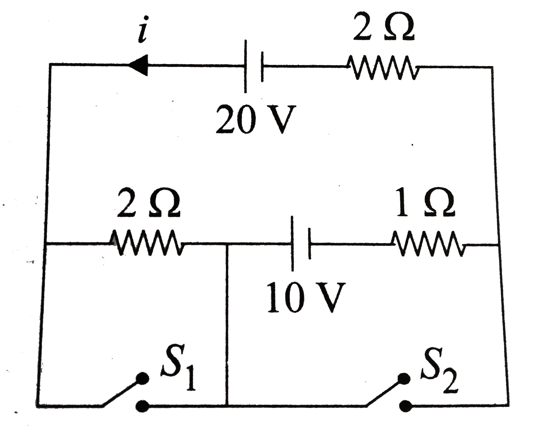
i=53A when S1 is closed and S2 is open
i=5A when S1 is open S2 is closed
i=2A when S1 and S2 both are open
i=10 A when both S1 and S2 are closed
The correct Answer is:B, C, D
b., c., d.
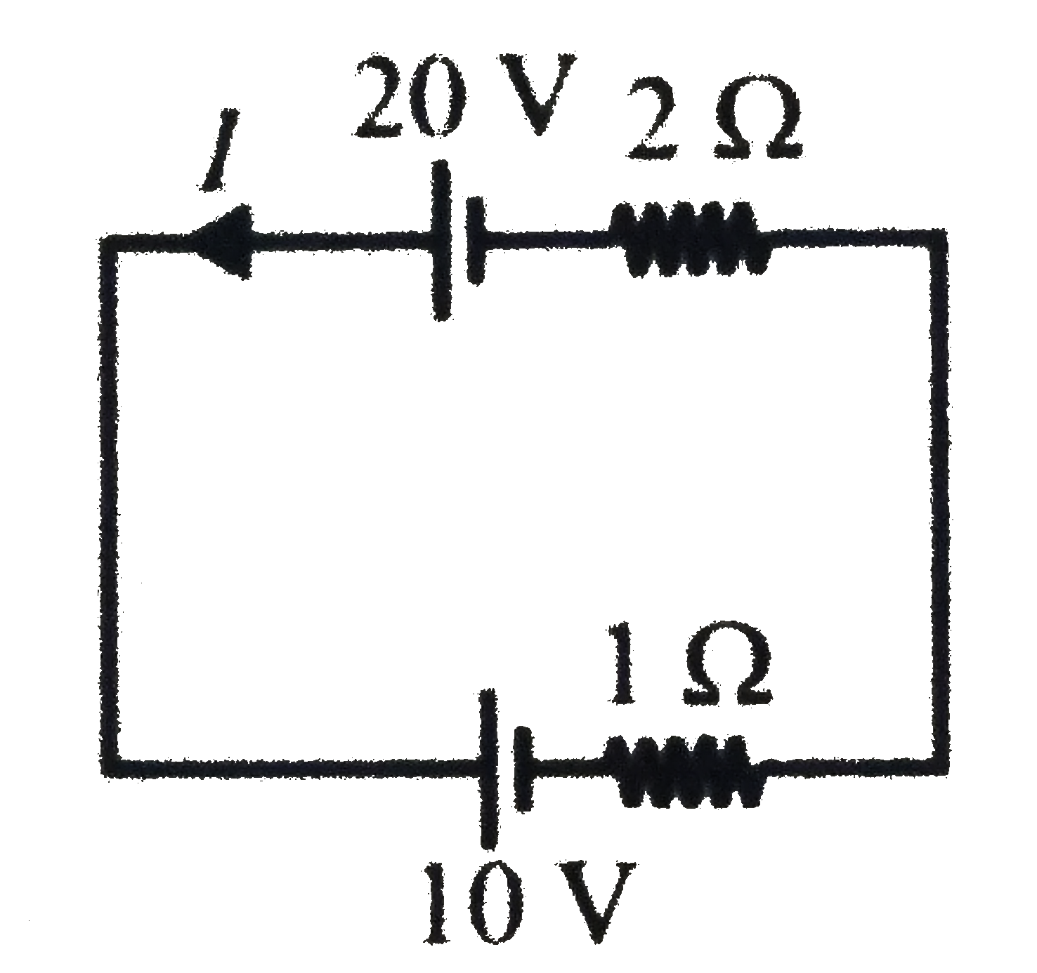
When S2 is closed and S2 is open
I=20−103=103A
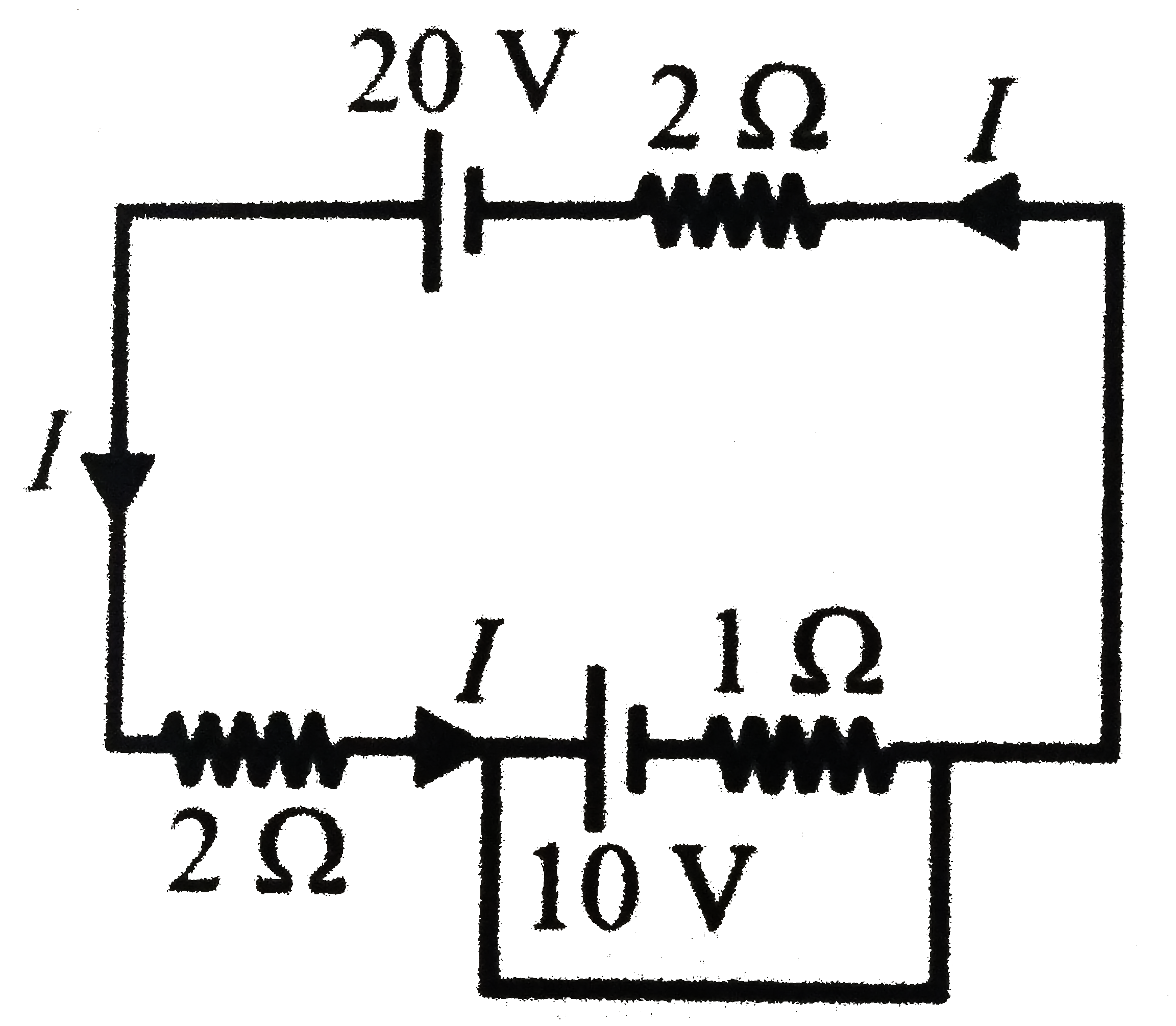
When S1 is open and S2 is closed
Taking outer loop
−2I−2I+20=0
or I=204A=5A
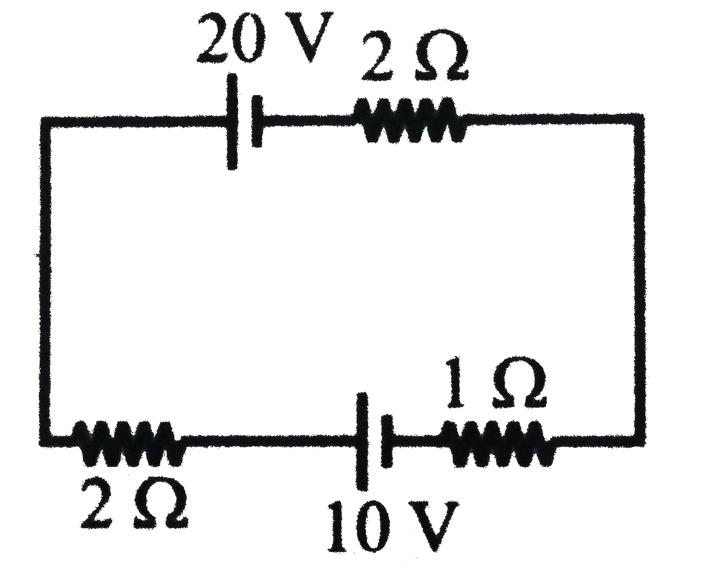
When S1 and S2 both are open
I=20−105=2A
When both are closed
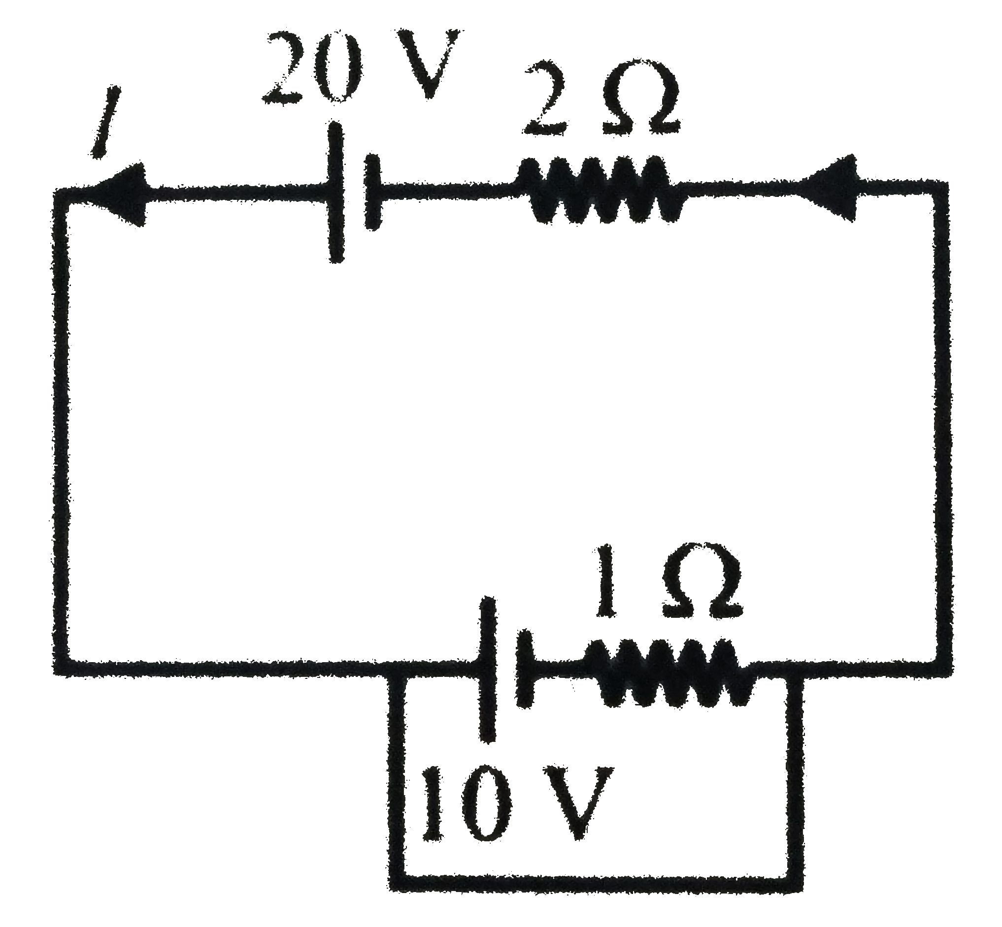
Again taking outer loop I=202=10A.
Topper's Solved these Questions
- BOOK - CENGAGE PHYSICS ENGLISHCHAPTER - MISCELLANEOUS VOLUME 3EXERCISE - Assertion and Reason8videos
MISCELLANEOUS VOLUME 3
- BOOK - CENGAGE PHYSICS ENGLISHCHAPTER - MISCELLANEOUS VOLUME 3EXERCISE - Integer Answer Type11videos
MISCELLANEOUS VOLUME 3
- BOOK - CENGAGE PHYSICS ENGLISHCHAPTER - MISCELLANEOUS VOLUME 3EXERCISE - Assertion-Reasoning Type1videos
MISCELLANEOUS VOLUME 3
- BOOK - CENGAGE PHYSICS ENGLISHCHAPTER - MAGNETIC FIELD AND MAGNETIC FORCESEXERCISE - Multiple Correct Answer type2videos
MAGNETIC FIELD AND MAGNETIC FORCES
- BOOK - CENGAGE PHYSICS ENGLISHCHAPTER - MISCELLANEOUS VOLUME 5EXERCISE - Integer12videos
MISCELLANEOUS VOLUME 5
Similar Questions
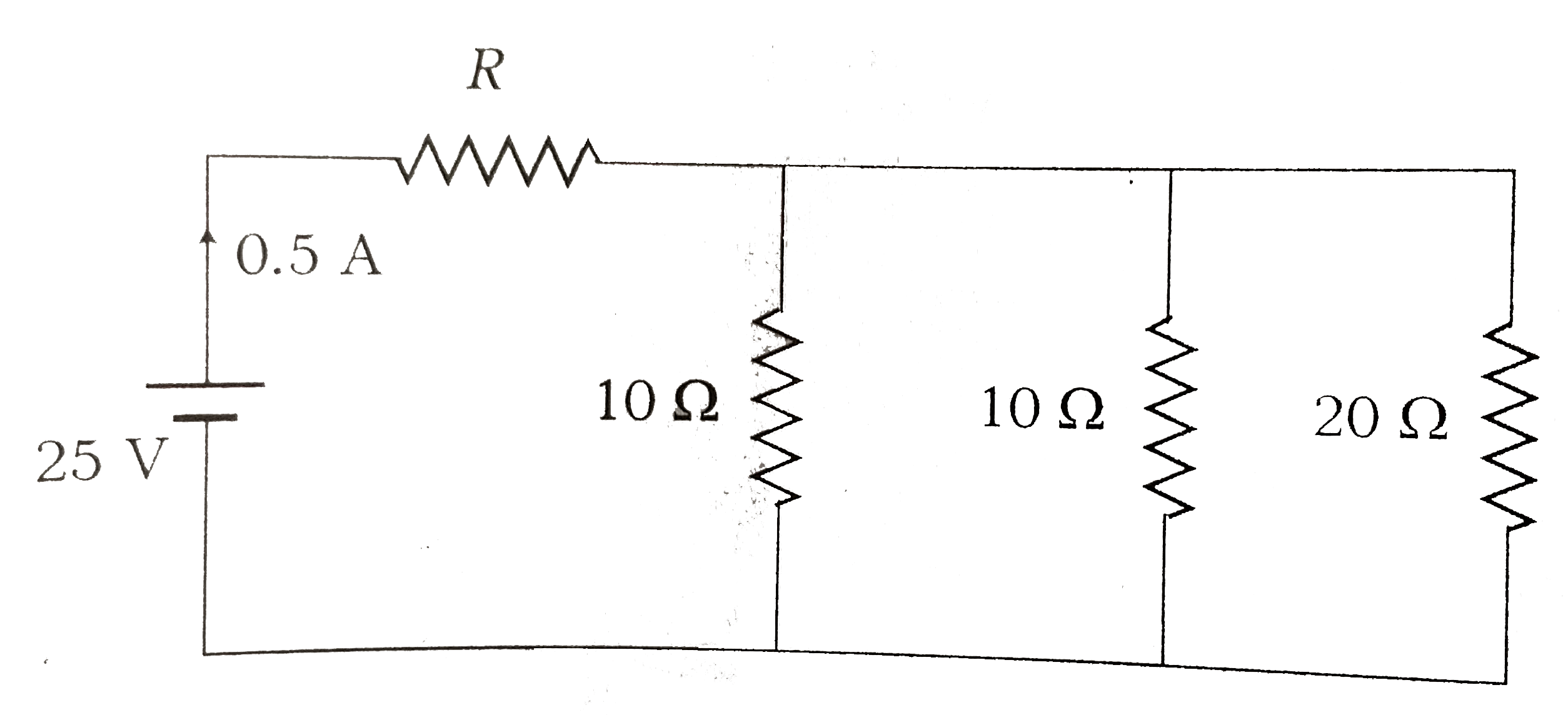
For the circuit shown in figure,
 View Solution
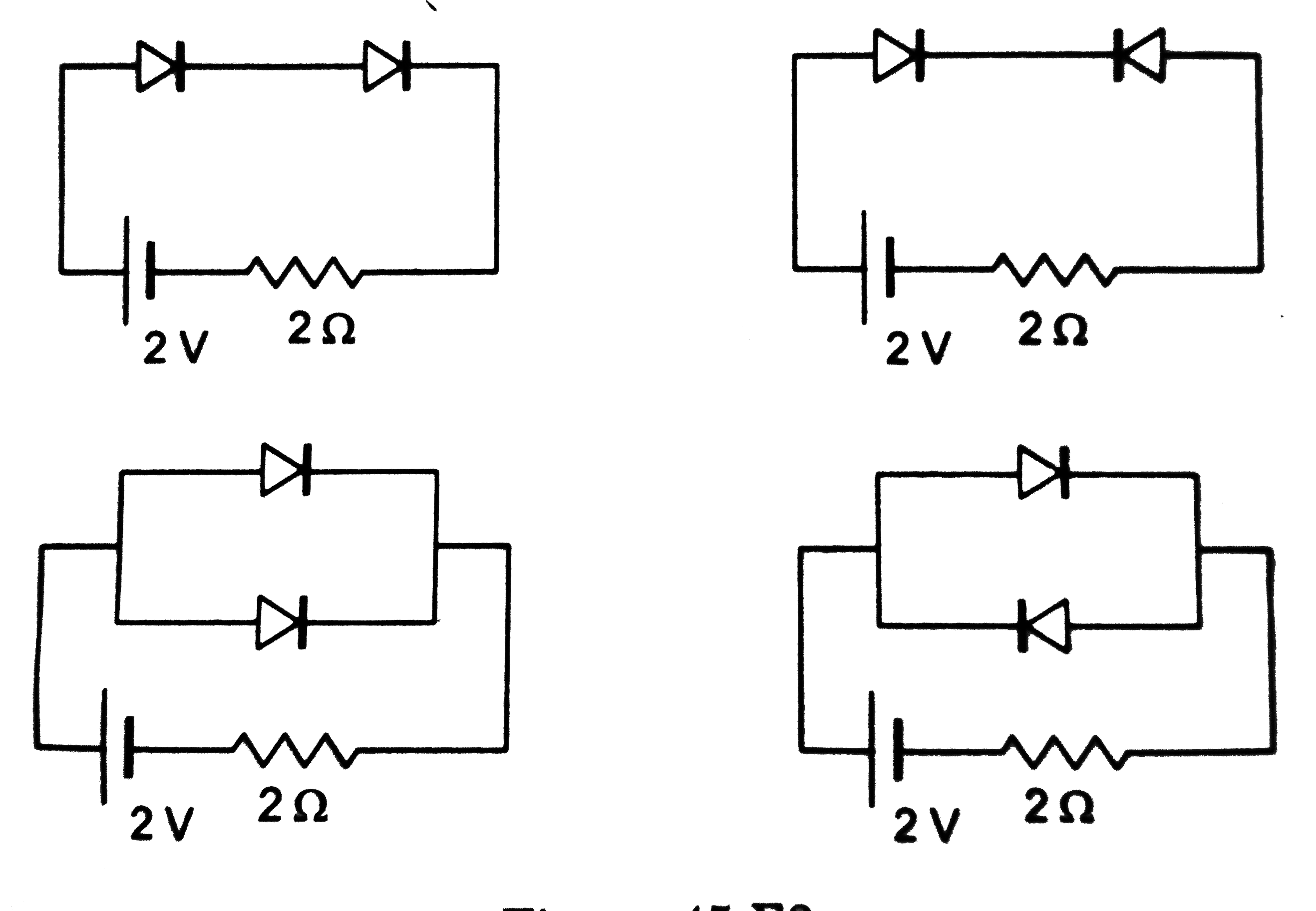
Find the current through the resistance in the circuits shown in figure
 View Solution
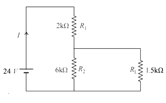
For the circuit shown in figure
 View Solution
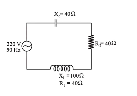
Calculate the power factor of the circuit shown in figure
 View Solution
For the circuit shown in figure, the equivalent capacitance of the combination is
 View Solution
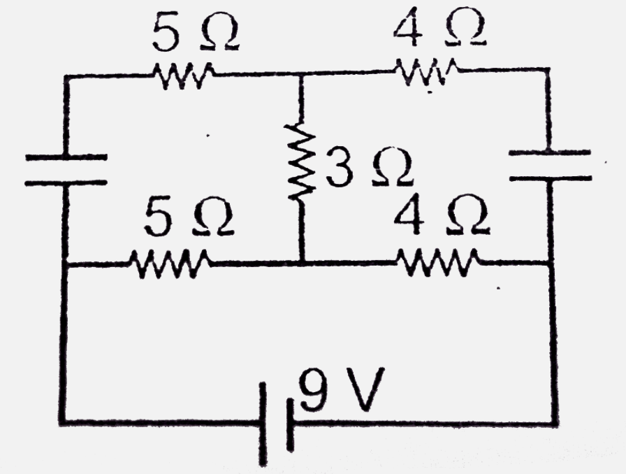
The power consumption by the circuit shown in figure at steady state is
 View Solution
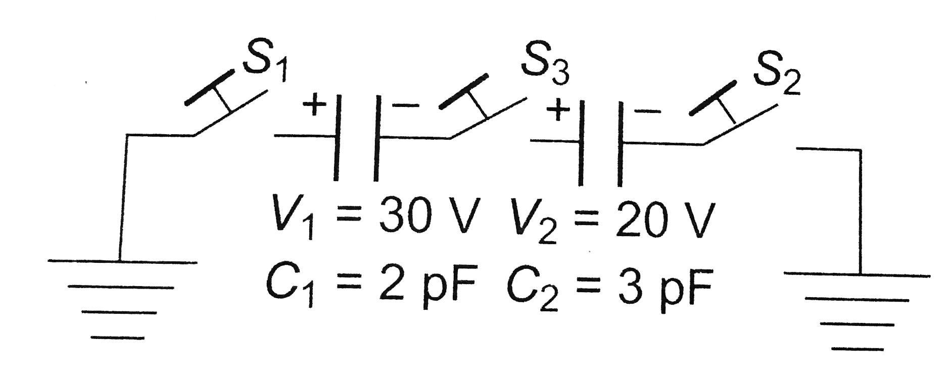
For the circuit shown in figure, which of the following statements is true ?
 View Solution
In the circuit shown in the figure
 . View Solution
In the circuit shown in the figure,
 View Solution
In the circuit shown in the figure , V must be -
 View Solution

