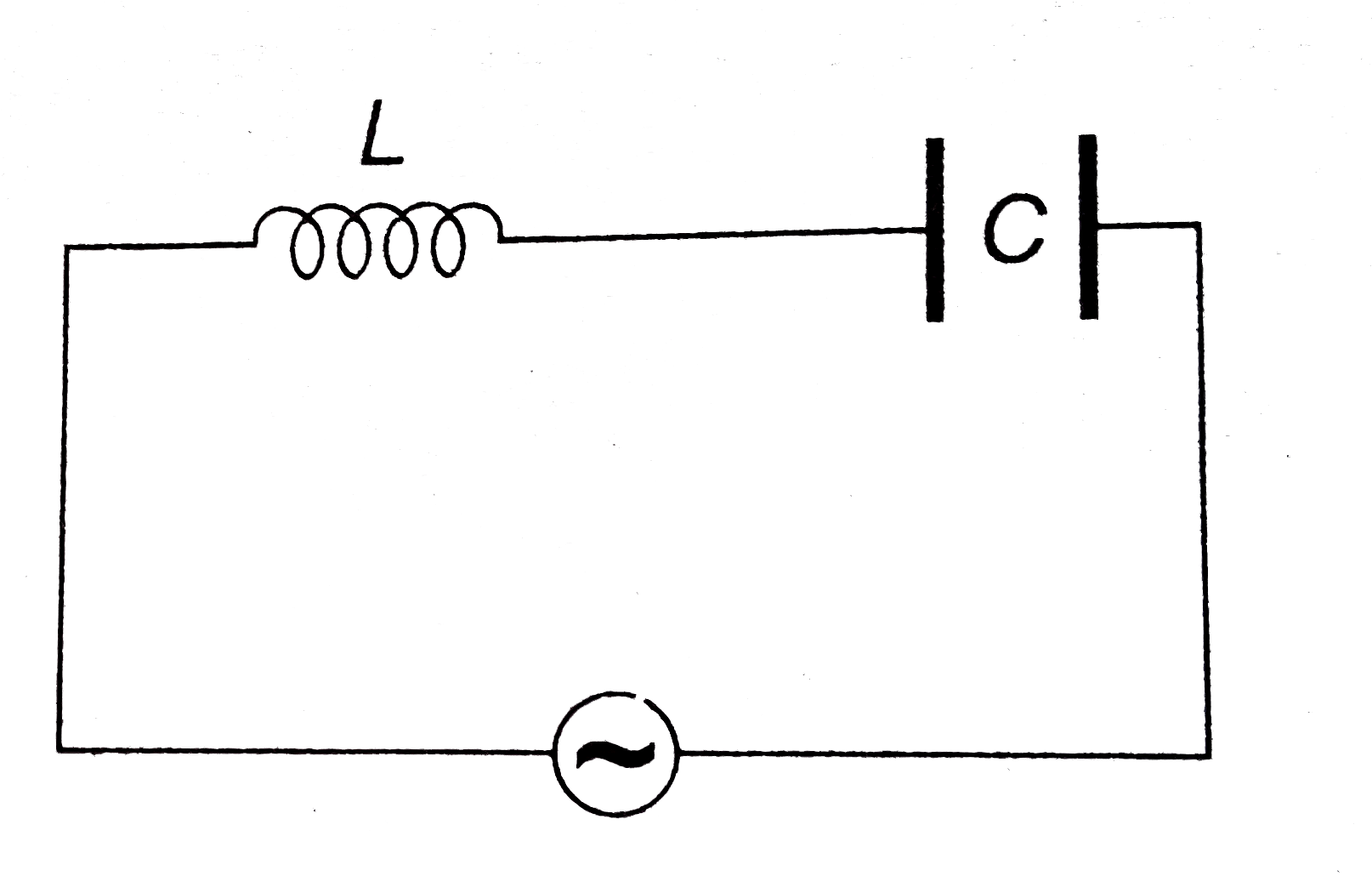
In the circuit shown in figure the voltage in L and in C are
 .
.
A
in phase
B
out of phase by 90∘
C
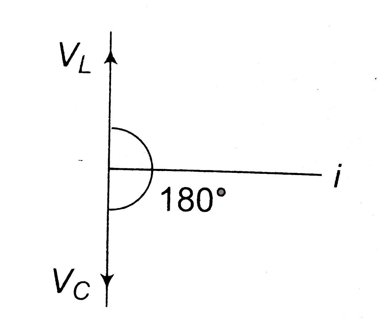
out of phase by 180∘
D
in a phase difference which depends upon the values of L C .
Video Solution
Text Solution
The correct Answer is:C
 .
.
|
Topper's Solved these Questions
Similar Questions
Knowledge Check
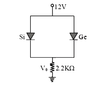
In the circuit shown in figure, Voltage V0 is
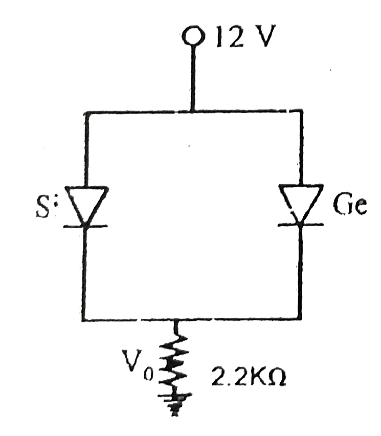 A11.7 voltB11.3 voltC0DNone
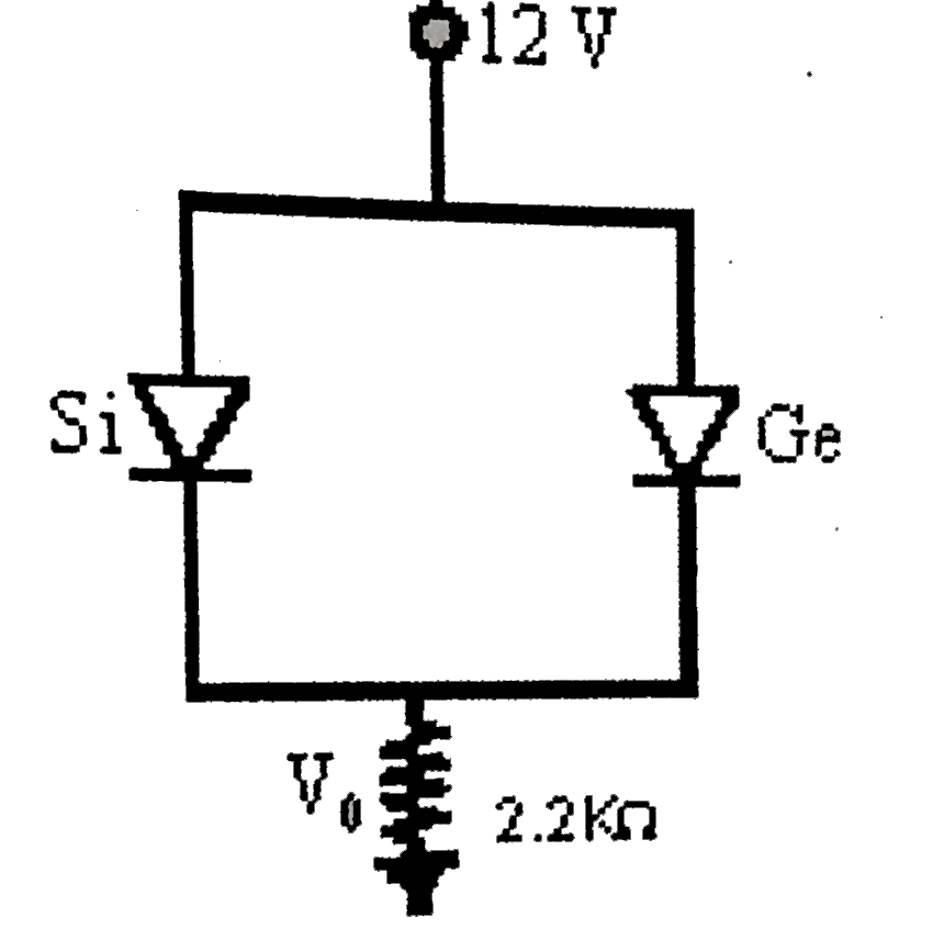
In the circuit shown infigure, voltage V0 is,A11.7 voltB11.3 voltC0DNone of theseIn the L-C-R circuit as shown in figure,
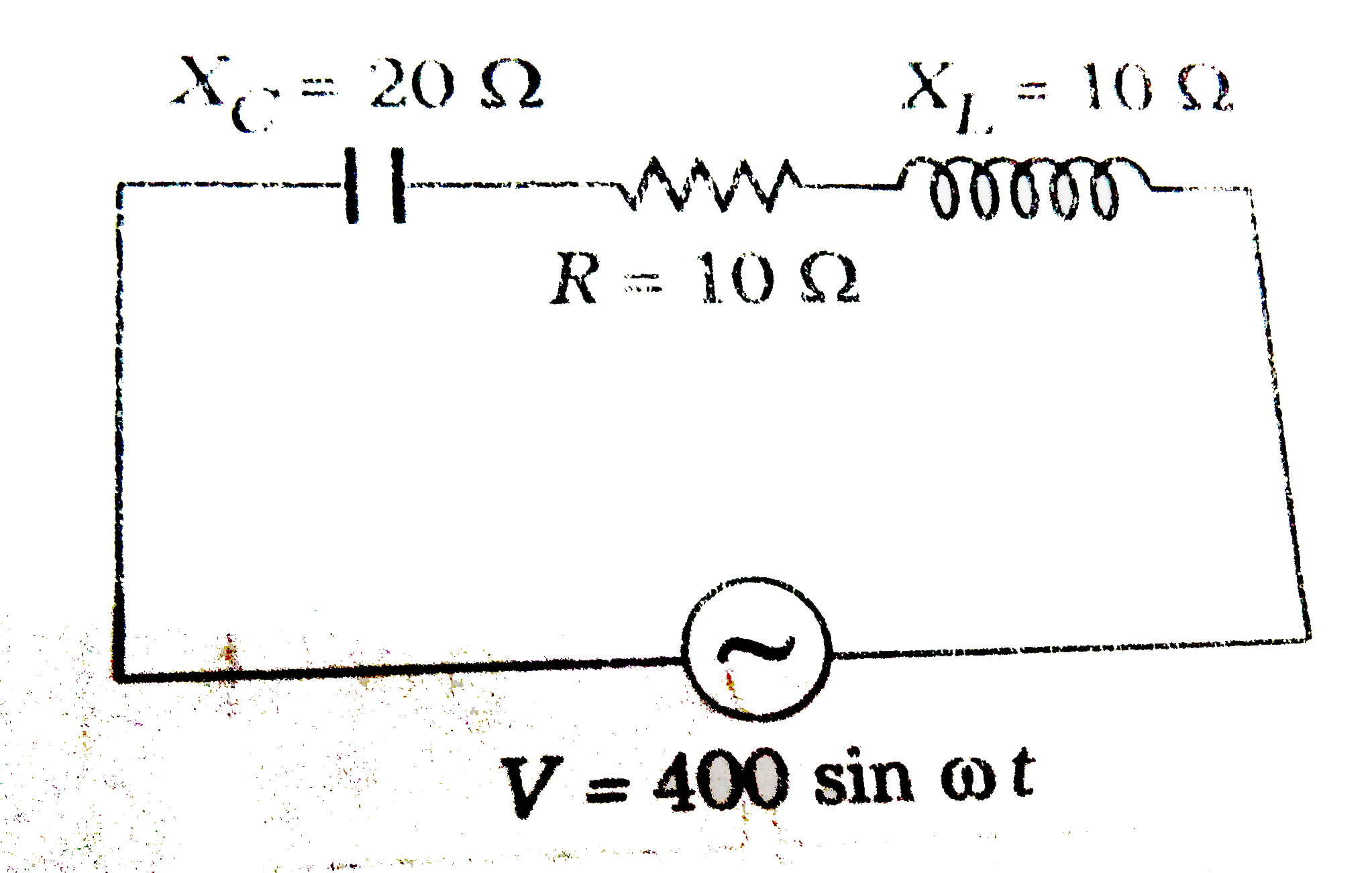 ACurrent will lead the voltageBRuns value of current is 20 ACPower factor of the circuit is 1√2DVoltage drop across resistance is 200 V
In the circuit shown in figure, the final voltage drop across the capacitor C is :
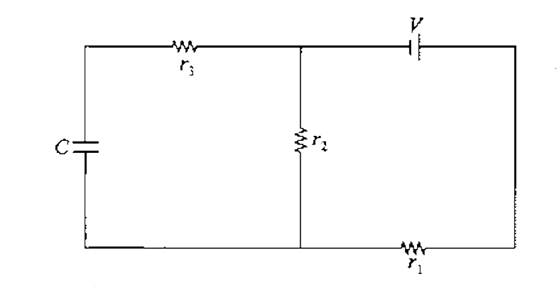
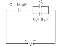
View SolutionIn the circuit shown in the figure, the total charge is 750μC and the voltage across capacitor C2 is 20 V. Then the charge on capacitor C2 is:
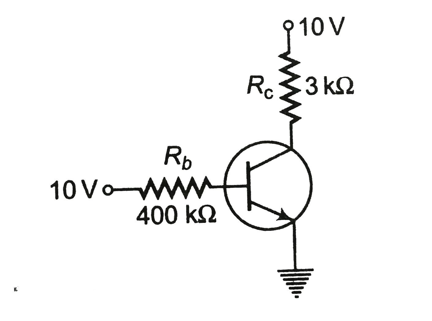
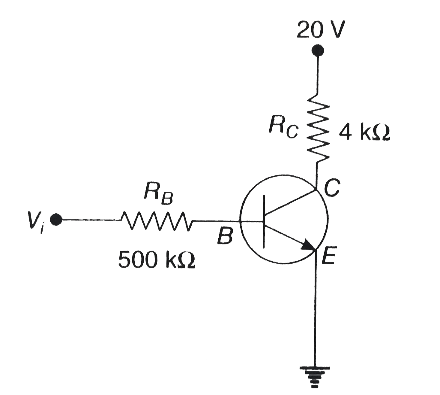
View SolutionIn the circuit shown in the figure, the input voltage Vi is 20V,VBE=0 and VCE=0. The values of IB,IC and β are given by:
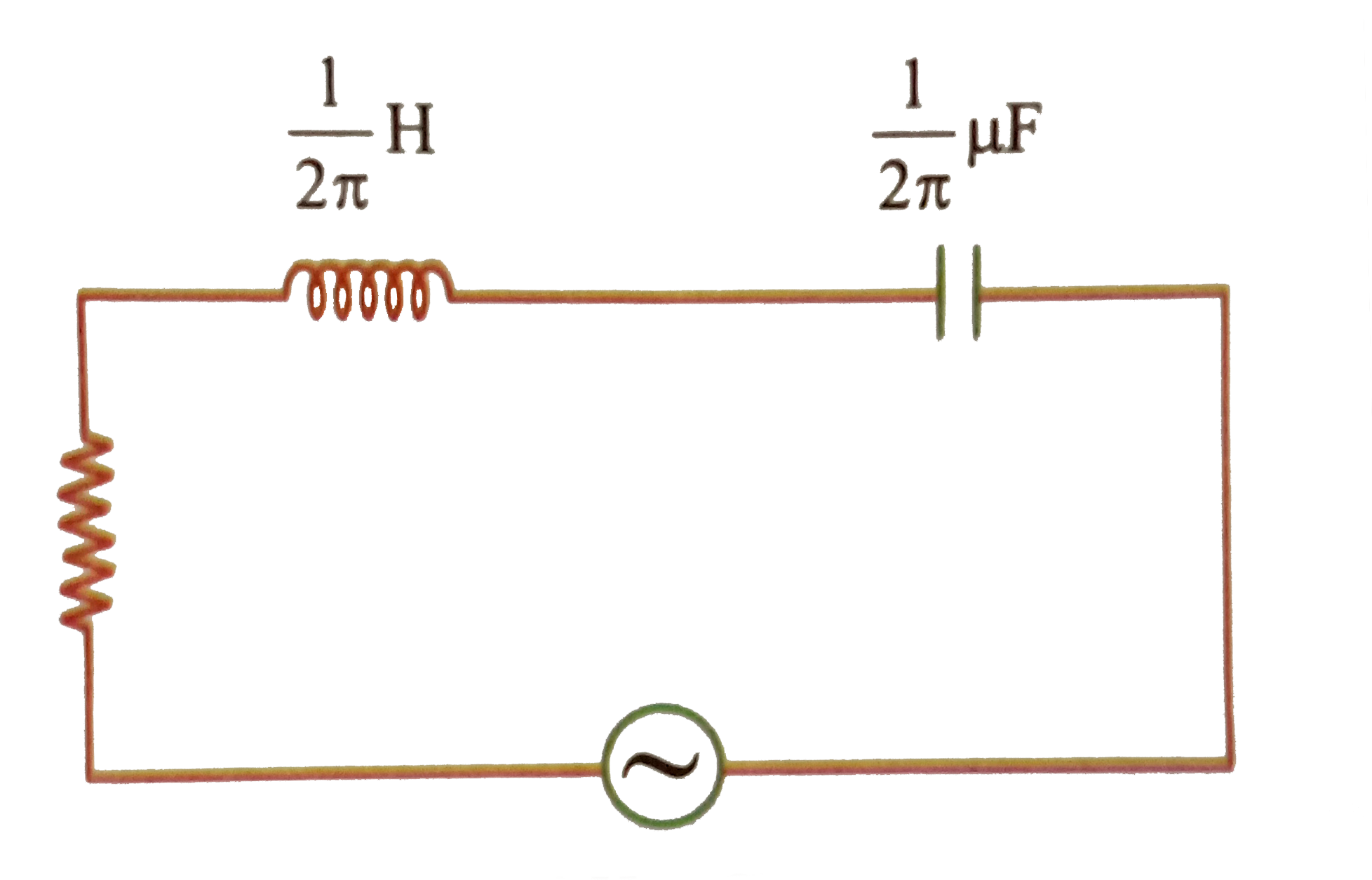
View SolutionIn the a.c circuit shown in figure, the supply voltage has a constant r.m.s value but variable frquency f. Resonance frequency is
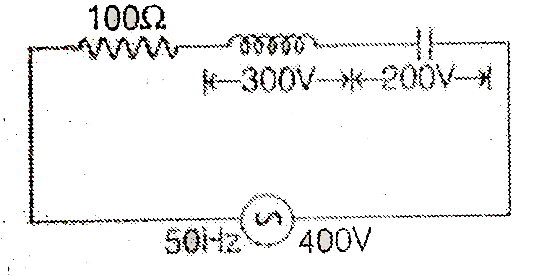
View SolutionIn the circuit shown in figure current in the circuit is
View Solution

