State Ohm's law and draw a neat labelled circuit diagram containing a battery, a key, a voltmeter, an ammeter, a rheostat and an unknown resistance to verify it.
Step-by-Step Solution:
1. State Ohm's Law:
- Ohm's Law states that the potential difference (V) across a conductor is directly proportional to the current (I) flowing through it, provided the temperature and material of the conductor remain constant. Mathematically, it is expressed as:
\(
V = R \times I
\)
where \( R \) is the resistance of the conductor.
2. Understanding the Components:
- Battery: Provides the necessary voltage (potential difference) in the circuit.
- Key (Switch): Used to open or close the circuit.
- Ammeter: Measures the current flowing through the circuit.
- Rheostat: A variable resistor used to adjust the current in the circuit.
- Unknown Resistance: The resistance whose value we want to determine.
- Voltmeter: Measures the potential difference across the unknown resistance.
3. Drawing the Circuit Diagram:
- Start by drawing the battery symbol, indicating the positive and negative terminals.
- Connect the key (switch) in series with the battery.
- Connect the ammeter in series after the key.
- Add the rheostat in series to allow for current adjustment.
- Connect the unknown resistance in series after the rheostat.
- Finally, connect the voltmeter in parallel across the unknown resistance.
4. Labeling the Circuit Diagram:
- Clearly label each component: Battery (V), Key, Ammeter (A), Rheostat (R), Unknown Resistance (R), and Voltmeter (V).
- Ensure that the connections are clear and that the direction of current flow is indicated.
Circuit Diagram:
±−−−(V)−−−−(Key)−−−−(A)−−−−(Rheostat)−−−−(Runknown)−−−−+∣∣±−−−−−−−−−−−−−−−−−−−−(V)−−−−−−−−−−−−−−−−−−−−−−−−−−−−−−−−−−+
- Ohm's Law states that the potential difference (V) across a conductor is directly proportional to the current (I) flowing through it, provided the temperature and material of the conductor remain constant. Mathematically, it is expressed as:
\(
V = R \times I
\)
where \( R \) is the resistance of the conductor.
- Battery: Provides the necessary voltage (potential difference) in the circuit.
- Key (Switch): Used to open or close the circuit.
- Ammeter: Measures the current flowing through the circuit.
- Rheostat: A variable resistor used to adjust the current in the circuit.
- Unknown Resistance: The resistance whose value we want to determine.
- Voltmeter: Measures the potential difference across the unknown resistance.
- Start by drawing the battery symbol, indicating the positive and negative terminals.
- Connect the key (switch) in series with the battery.
- Connect the ammeter in series after the key.
- Add the rheostat in series to allow for current adjustment.
- Connect the unknown resistance in series after the rheostat.
- Finally, connect the voltmeter in parallel across the unknown resistance.
- Clearly label each component: Battery (V), Key, Ammeter (A), Rheostat (R), Unknown Resistance (R), and Voltmeter (V).
- Ensure that the connections are clear and that the direction of current flow is indicated.
±−−−(V)−−−−(Key)−−−−(A)−−−−(Rheostat)−−−−(Runknown)−−−−+∣∣±−−−−−−−−−−−−−−−−−−−−(V)−−−−−−−−−−−−−−−−−−−−−−−−−−−−−−−−−−+
Topper's Solved these Questions
- CURRENT ELECTRICITYBOOK - ICSECHAPTER - CURRENT ELECTRICITYEXERCISE - EXERCISE-8(A) ( MULTIPLE CHOICE TYPE)
2 Videos
- CURRENT ELECTRICITYBOOK - ICSECHAPTER - CURRENT ELECTRICITYEXERCISE - EXERCISE-8(A)(NUMERICALS )
16 Videos
- CURRENT ELECTRICITYBOOK - ICSECHAPTER - CURRENT ELECTRICITYEXERCISE - EXERCISE-8(C) NUMERICALS
35 Videos
- CALORIMETRYBOOK - ICSECHAPTER - CALORIMETRYEXERCISE - EXERCISE-11(B) (NUMERICALS)
15 Videos
- ELECTRO-MAGNETISM BOOK - ICSECHAPTER - ELECTRO-MAGNETISM EXERCISE - EXERCISE-10 (C) NUMERICALS
1 Videos
Similar Questions
Draw a well labelled circuit diagram for the verification of Ohm.s law.
View SolutionState Ohm's law. Draw a labelled circuit diagram to verify this law in the laboratory. If you draw a graph between the potential difference and current flowing through a metallic conductor, what kind of curve will you get? Explain how would you use this graph to determine the resistance of the conductor.
View Solution
Knowledge Check
State ohm's law.
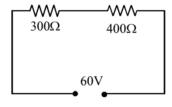
In the circuit shown in figure, a voltmeter reads 30 volts when it is connected across 400 ohm resistance. Calculate what the same voltmeter will read when it is connected across the 300 ohm resistance.
 A30VB12.5VC15VD22.5V
Draw a neat and labelled diagram of a screw gauge. Name its main parts and state their functions.
View SolutionDraw a circuit diagram of an electric circuit containing a cell, a key, an ammeter, a resistance of 2Ω in series with a combination of two resistors (4Ω each) in parallel and a voltmeter across the parallel combination. Will the potential difference across the 2Ω resistor be the same as that across the parallel combination of 4Ω resistors ? Give reason.
View SolutionDraw a labelled circuit diagram of a potentiometer to measure internal resistance of a cell. Write the working formula. (Derivation not required).
View SolutionDraw a schematic diagram of a circuit consisting of a battery of three cells of 2V each, a 5 ohm resistor, an 8 ohm resistor, and a 12 ohm resistor, and a plug key, all connected in series.
View SolutionDraw a neat and labelled diagram of a fish and answer the following questions :
State wheter it is an aquatic animal or a terrestrial animal . Why ?
View SolutionYou have following material :
An ammeter ( 0-1A0 ,a voltmeter ( 0-3V) , a resistor of 20Ω , a key, a rheostat, a battery of 3 V and seven connecting wires.
Using this material draw a labelled circuit diagram to study the dependence of potential difference (V) across a resistor ont he current (I) passing through it.
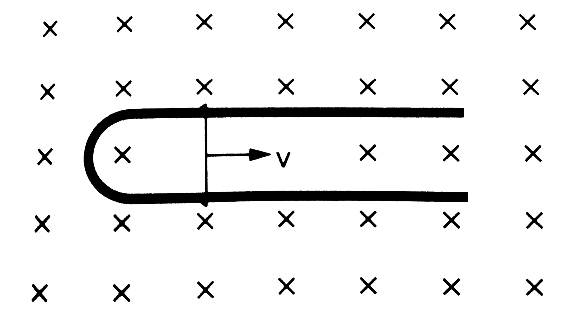
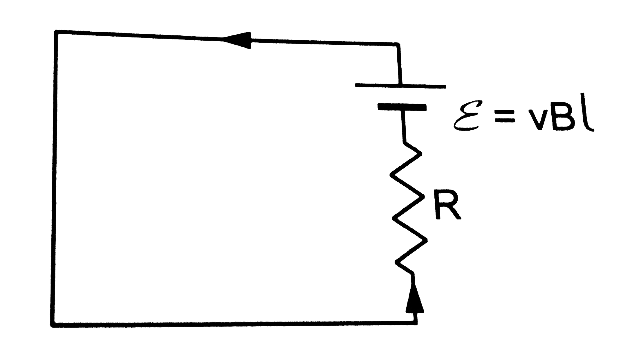
View SolutionShows a wire of length l which can slide on a U- shaped rail of negligible resistance. The resistance of the wire is R. The wire is pulled ot the right with a constant speed v. Draw an equivalent circuit diagram representing the induced emf by a battery. Find the current in the wire usingj this diagram.


View Solution
