Draw a schematic diagram of a circuit consisting of a battery of three cells of 2V each, a 5 ohm resistor, an 8 ohm resistor, and a 12 ohm resistor, and a plug key, all connected in series.
To draw a schematic diagram of the described circuit, follow these steps:
Step 1: Draw the Battery
1. Start by drawing three cells in series. Each cell represents a 2 V battery.
2. Draw the first cell as a long rectangle with a positive (+) terminal on the top and a negative (-) terminal on the bottom.
3. Repeat this for the second and third cells, ensuring that the negative terminal of one cell connects to the positive terminal of the next cell.
Step 2: Connect the Cells
1. Connect the negative terminal of the first cell to the positive terminal of the second cell.
2. Connect the negative terminal of the second cell to the positive terminal of the third cell.
3. The total voltage across the three cells in series will be 6 V (2 V + 2 V + 2 V).
Step 3: Draw the Plug Key
1. After the last cell, draw a switch (plug key) symbol. This is typically represented by a break in the line with a small circle or a line that can be opened or closed.
Step 4: Draw the Resistors
1. From the plug key, draw a line to the first resistor (5 ohm). Represent the resistor with a zigzag line.
2. Label this resistor as "5 Ω".
3. Continue the line from the 5-ohm resistor to the next resistor (8 ohm), also represented with a zigzag line and labeled "8 Ω".
4. Finally, connect the 8-ohm resistor to the last resistor (12 ohm), again represented with a zigzag line and labeled "12 Ω".
Step 5: Complete the Circuit
1. Connect the last resistor back to the negative terminal of the first cell, completing the circuit.
2. Ensure all components are clearly labeled and the connections are neat.
Final Diagram
Your final schematic diagram should show:
- Three cells in series (totaling 6 V)
- A plug key connected in series
- Three resistors (5 Ω, 8 Ω, and 12 Ω) connected in series
1. Start by drawing three cells in series. Each cell represents a 2 V battery.
2. Draw the first cell as a long rectangle with a positive (+) terminal on the top and a negative (-) terminal on the bottom.
3. Repeat this for the second and third cells, ensuring that the negative terminal of one cell connects to the positive terminal of the next cell.
1. Connect the negative terminal of the first cell to the positive terminal of the second cell.
2. Connect the negative terminal of the second cell to the positive terminal of the third cell.
3. The total voltage across the three cells in series will be 6 V (2 V + 2 V + 2 V).
1. After the last cell, draw a switch (plug key) symbol. This is typically represented by a break in the line with a small circle or a line that can be opened or closed.
1. From the plug key, draw a line to the first resistor (5 ohm). Represent the resistor with a zigzag line.
2. Label this resistor as "5 Ω".
3. Continue the line from the 5-ohm resistor to the next resistor (8 ohm), also represented with a zigzag line and labeled "8 Ω".
4. Finally, connect the 8-ohm resistor to the last resistor (12 ohm), again represented with a zigzag line and labeled "12 Ω".
1. Connect the last resistor back to the negative terminal of the first cell, completing the circuit.
2. Ensure all components are clearly labeled and the connections are neat.
Your final schematic diagram should show:
- Three cells in series (totaling 6 V)
- A plug key connected in series
- Three resistors (5 Ω, 8 Ω, and 12 Ω) connected in series
Topper's Solved these Questions
Similar Questions
Draw a schematic diagram of circuit consisting of a battery of 3 cells of 2V each, combination of three resistors 10ohm, 20ohm and 30ohm connected in parallel, a plug key and an ammeter,all connected in series. Use this circuit to find the following
(i) Current through each resistor.
(ii) Total current in circuit
(iii)Total Effective resistance of circuit
View SolutionDraw a circuit diagram of an electric circuit containing a cell, a key, an ammeter, a resistance of 2Ω in series with a combination of two resistors (4Ω each) in parallel and a voltmeter across the parallel combination. Will the potential difference across the 2Ω resistor be the same as that across the parallel combination of 4Ω resistors ? Give reason.
View SolutionDraw a circuit diagram when three bulbs are connected in series with a battery of cells, which are also connected in series.
View SolutionBy a cell a current of 0.9 A flows through 2 ohm resistor and 0.3A through 7 ohm resistor. The internal resistance of the cell is
View SolutionState Ohm's law and draw a neat labelled circuit diagram containing a battery, a key, a voltmeter, an ammeter, a rheostat and an unknown resistance to verify it.
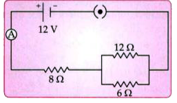
View SolutionThree resistors are connected to a 12 V battery as shown in the figure given below :

What is the current through the 8 ohm resistor ?
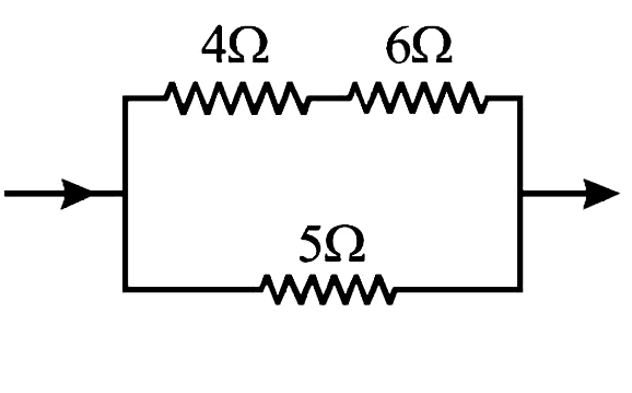
View SolutionThe electric current through 10 ohm resistor in circuit given below is
View SolutionIn the circuit shown in fig the heat produced in the 5 ohm resistor due to the current flowing through it is 10 calories per second.

The heat generated in the 4 ohms resistor is
View SolutionResistors of 1, 2, 3 ohm are connected in the form of a triangle. If a 1.5V cell of negligible internal resistance is connected across 3 ohm resistor, the current flowing through this resistance will be
View SolutionRedraw the circuit of Q.12, putting in an ammeter to measure the current through the resistors and a voltmeter to measure the voltage across the 12ohm resistor. What would be the readings in the ammeter and the voltmeter ?
View Solution
