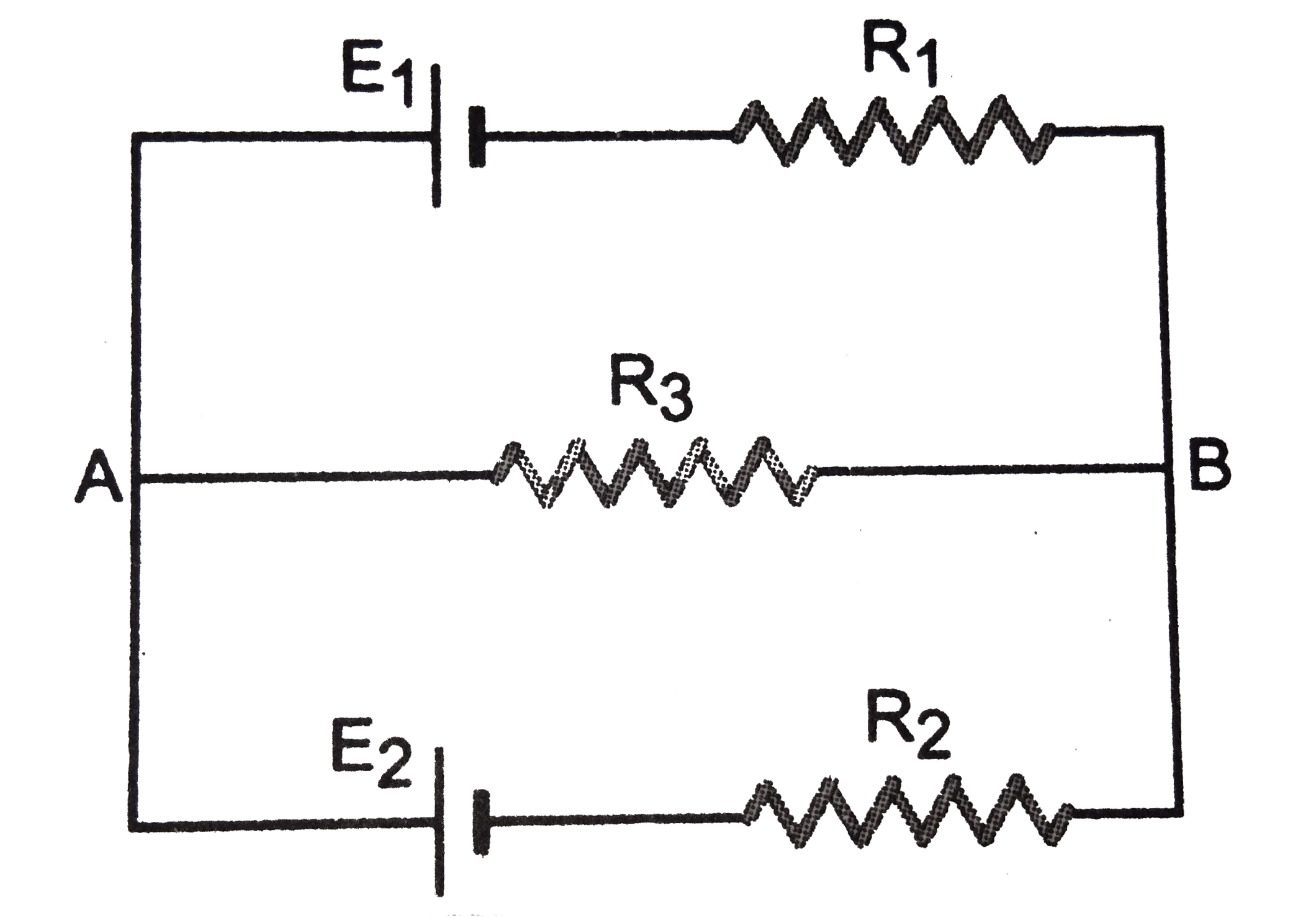
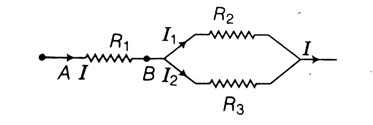
The circuit diagram given below shows the combination of three resistors R1,R2 and R3:
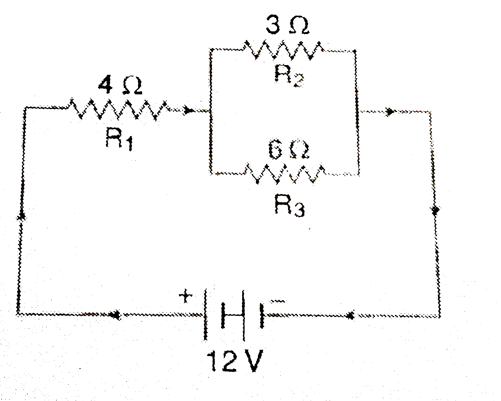
Find: (i) total resistance of the circuit.
(ii) total current flowing in the circuit.
(iii) the potential difference across R1.
The correct Answer is:(i) 6Ω (ii) 2A (iii) 8V
Step by step video, text & image solution for The circuit diagram given below shows the combination of three resistors R_(1),R_(2) and R_(3): Find: (i) total resistance of the circuit. (ii) total current flowing in the circuit. (iii) the potential difference across R_(1). by Physics experts to help you in doubts & scoring excellent marks in Class 10 exams.
Updated on:21/07/2023Topper's Solved these Questions
- ELECTRICITY BOOK - LAKHMIR SINGH & MANJIT KAURCHAPTER - ELECTRICITY EXERCISE - Very Short Answer Type Questions
1 Videos
- ELECTRICITY BOOK - LAKHMIR SINGH & MANJIT KAURCHAPTER - ELECTRICITY EXERCISE - Short Answer Type Questions
2 Videos
- ELECTRICITY BOOK - LAKHMIR SINGH & MANJIT KAURCHAPTER - ELECTRICITY EXERCISE - Sample Problem
1 Videos
- MAGNETIC EFFECT OF ELECTRIC CURRENT BOOK - LAKHMIR SINGH & MANJIT KAURCHAPTER - MAGNETIC EFFECT OF ELECTRIC CURRENT EXERCISE - NCERT BOOK
2 Videos
Similar Questions
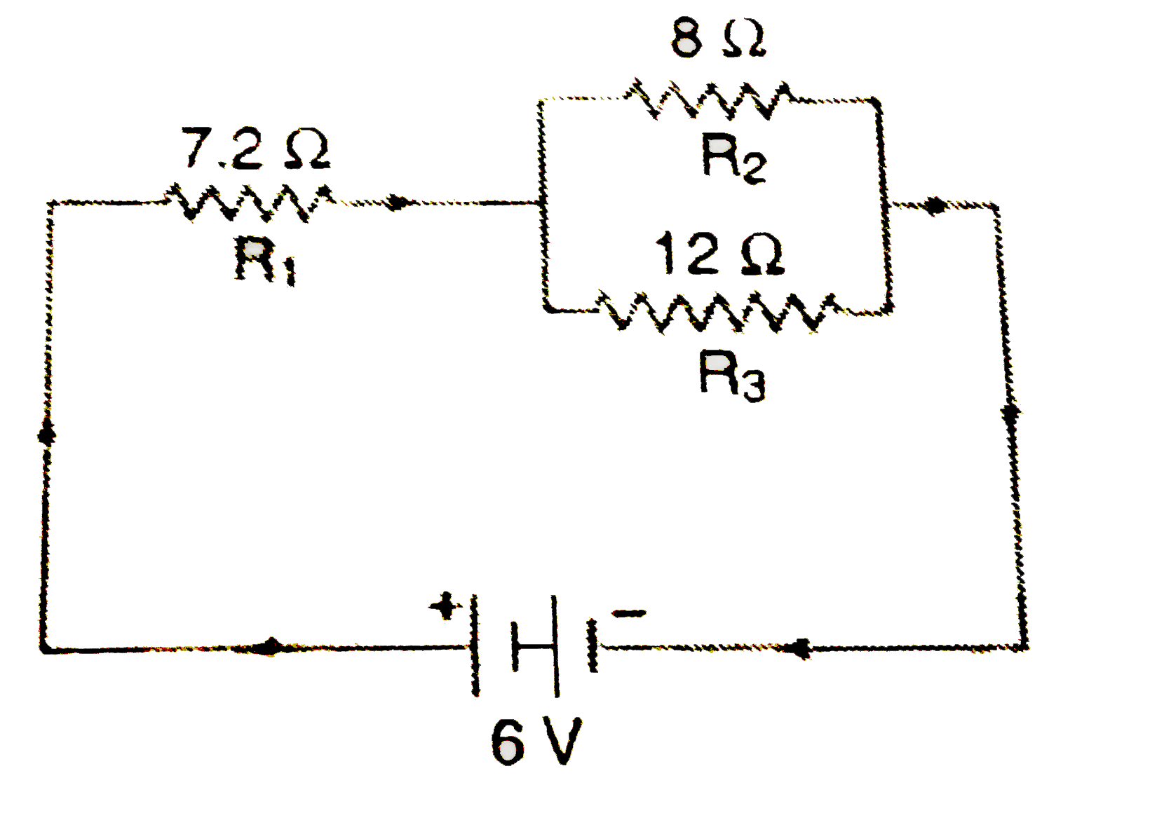
In the circuit diagram given alongside, find:
(i) total resistance of the circuit,
(ii) total current flowing in the circuit, and
(iii) the potential difference across R1
View Solution(a) what is meant by series and parallel combination of resistances ?
(b) in which case, series combination or parallel combination, the combined resistance is less than any of the individual resistances ?
(c ) How should two resistance of 2Ω each be connected so as to produce an equivalent resistance of 1Ω ?
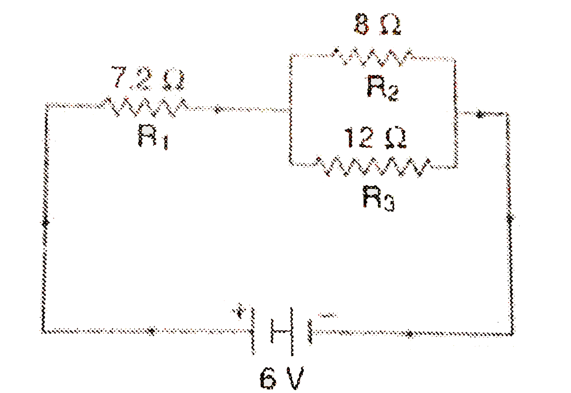
In the circuit diagram given here , find:
(i) total resistance of the circuit
(ii) total current flowing in the circuit, and
(iii) the potential difference across R1
View SolutionIn the given circuit, calculate -
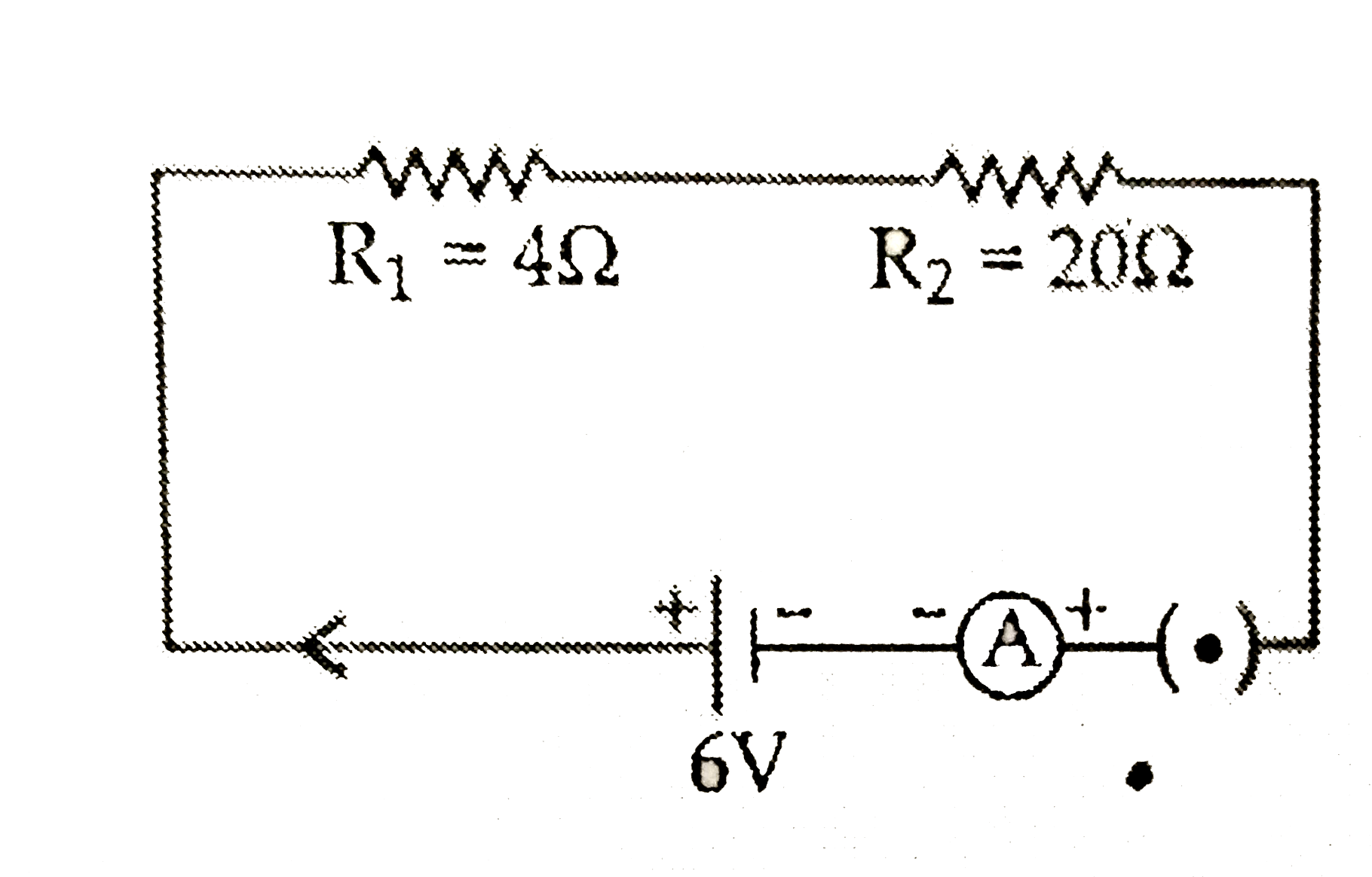
(a) the total resistance of the circuit,
(b) the current through the circuit, and
(c) the potential differences across R1andR2
View SolutionFind the potential differnce across R2 in the circuit
View SolutionStudy the electric circuit of Fig. 12.30 and find (i) the current flowing in the circuit and (ii) the potential difference across 10Ω resistor.
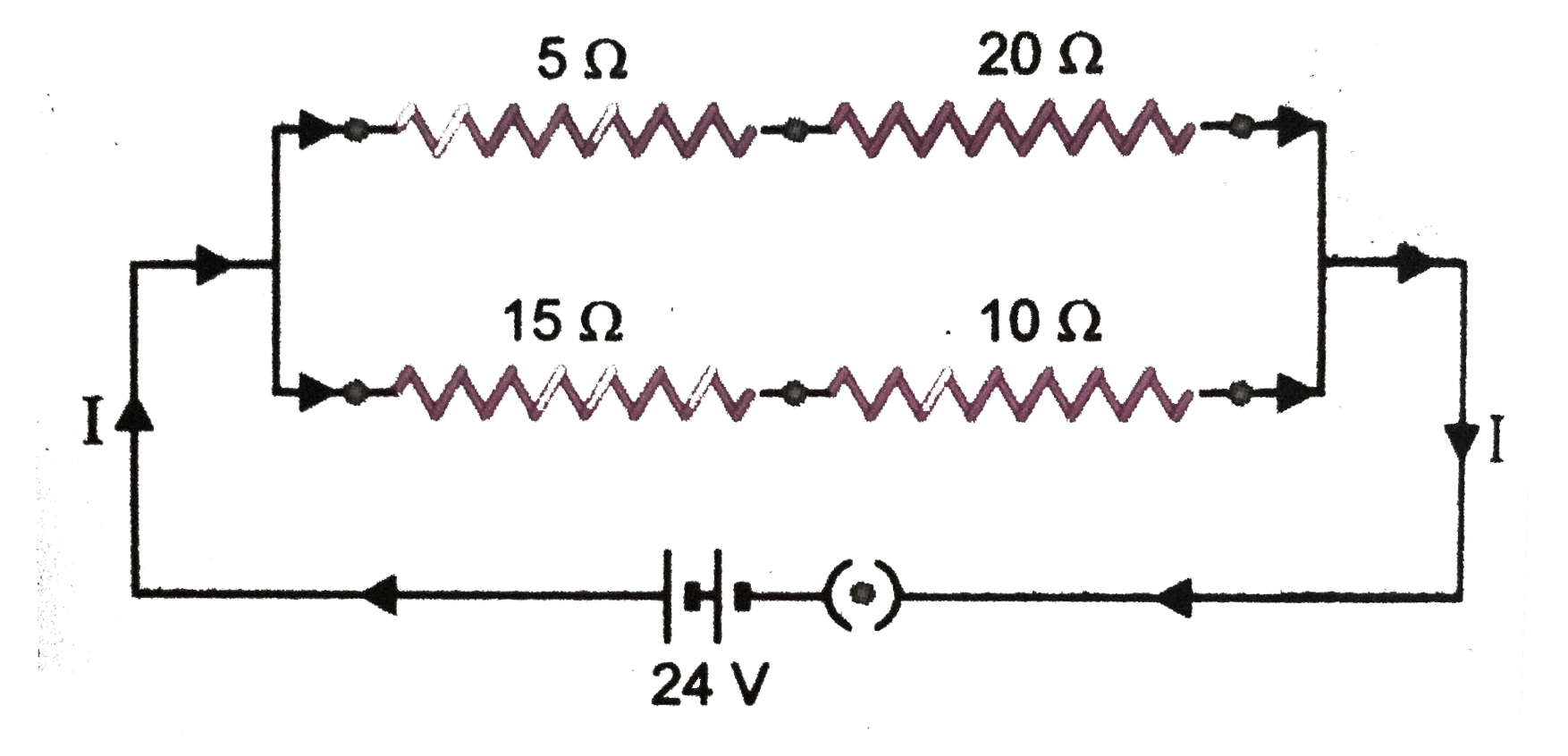
View SolutionA 24 volt battery is connected to the arrangement of resistances shown in (Fig.) Calculate
(i) the total effective resistance of the circuit,
(ii) the total current flowing in the circuit.
 .
.
View SolutionIn the circuit shown below, calculate the total resistance of the circuit and the current flowing through it.
View SolutionIn the circuit diagram given below, three resistors R1,R2, and R3 of 5Ω,10Ω and 30Ω, respectively are connected as shown.
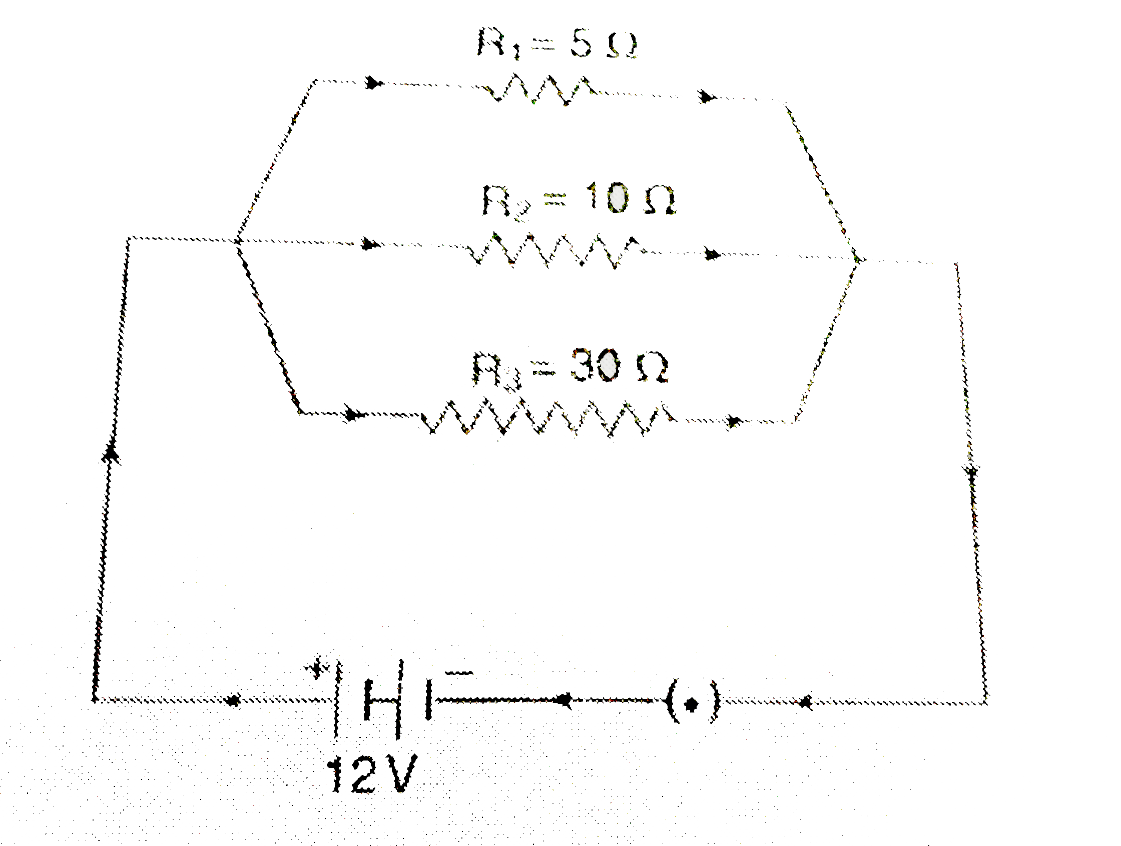
Calculate:
(a) current through each resistor.
(b) total current in the circuit.
(c) total resistance in the circuit.
View SolutionFind the currents going through the three resistors R_(v),R_(2)andR_(3) in the circuit of figure.
View SolutionThe circuit in figure, where there are three resistors R1,R2 and R3 . If the voltage between A and C is V, the current / is given by
View Solution
