The given figure is part of a circuit. All the values of the voltages, currents, resistances and the capacitance are mentioned in the figure. Study the circuit for a steady state condition of the capacitor to answer the following questions.

Potential difference between points a and b is
A
58 V
B
19 V
C
29 V
D
39 V
Text Solution
The correct Answer is:C
Here is the circuit redrawn with current flowing in all the branches.

No current will flow through the branch where the capacitor is connected. We apply krichhoff.s junction law at point d to know the current flowing through the branche def, which is 2+1=3A. Similarly, apllying the junction law at point c we get to know the current flowing in branch cf, which is also 2+1=3A. At point f these two streams of currents are added together to become 6 A to flow through fg.
To calculate charge and energy stored in the capacitor we need to know potential difference across its terminals. We can follow the path defc to add potential differences to get net potential difference between points d and c.
Vd−3×6−3×5+3×4=VC
⇒Vd−18−15+12=VC
⇒Vd−Vc=21V
Charge stored in the capacitor Q=CV=(5μF)×(21V)=105μF
Energy stored in the capacitor U=12CV2
=0.5×(5μF)×(21V)2=1102.5μJ
To calculate potential difference between a and b we can follow the path adefeb
Va−20−2×1−3×6−3×5+3×4+2×2+10=Vb
⇒Va−20−2−18−15+12+4+10=Vb
⇒Va−Vb=29V
|
Updated on:21/07/2023
Topper's Solved these Questions
- BOOK - MODERN PUBLICATIONCHAPTER - CURRENT ELECTRICITYEXERCISE - Objective Type Questions (MULTIPLE CHOICE QUESTIONS) (D. MULTIPLE CHOICE QUESTIONS ASSERTION REASON TYPE QUESTIONS)10videos
CURRENT ELECTRICITY
- BOOK - MODERN PUBLICATIONCHAPTER - CURRENT ELECTRICITYEXERCISE - Objective Type Questions (MULTIPLE CHOICE QUESTIONS) (D. MULTIPLE CHOICE QUESTIONS MATRIX MATCH TYPE QUESTIONS)1videos
CURRENT ELECTRICITY
- BOOK - MODERN PUBLICATIONCHAPTER - CURRENT ELECTRICITYEXERCISE - Objective Type Questions (MULTIPLE CHOICE QUESTIONS) (C. MULTIPLE CHOICE QUESTIONS WITH MORE THAN ONE CORRECT ANSWER)18videos
CURRENT ELECTRICITY
- BOOK - MODERN PUBLICATIONCHAPTER - ATOMS EXERCISE - Chapter Practice Test16videos
ATOMS
- BOOK - MODERN PUBLICATIONCHAPTER - DUAL NATURE OF RADIATION AND MATTER EXERCISE - CHAPTER PRACTICE TEST15videos
DUAL NATURE OF RADIATION AND MATTER
Similar Questions
Knowledge Check
- Question 1 - Select One
For the circuit figure, find the potential difference between points a and b:
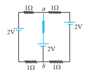 A2.4VB2.8VC2VD3.2v
 - Question 2 - Select One
There is a electric circuit as shown in the figure. Find potential difference between points a and b.
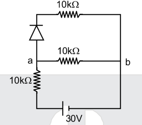 A3VB15VC10VD5V
 - Question 3 - Select One
For the circuit arrangement shown in figure, in the steady state condition charge on the capacitor is
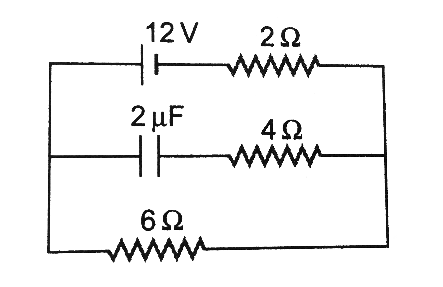 A12μCB14μCC2μCD18μC
For the circuit arrangement shown in figure, in the steady state condition charge on the capacitor is
 View Solution
In the circuit shown in figure potential difference between the points A and B in the steady state is
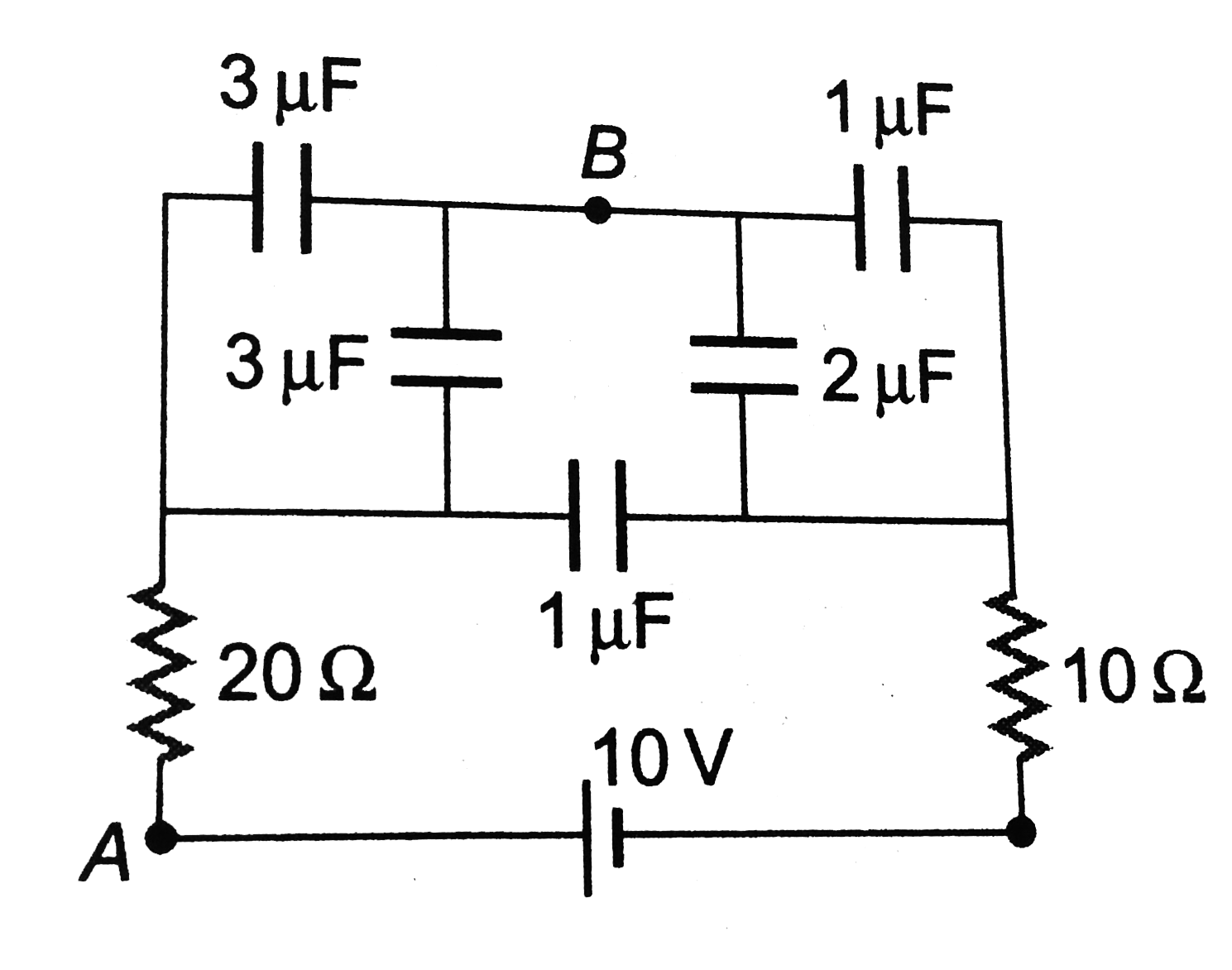 View Solution
In the circuit shown in figure potential difference between A and B is
 View Solution
In the circuit shown in figure potential difference between the points A and B in the steady state is
 View Solution
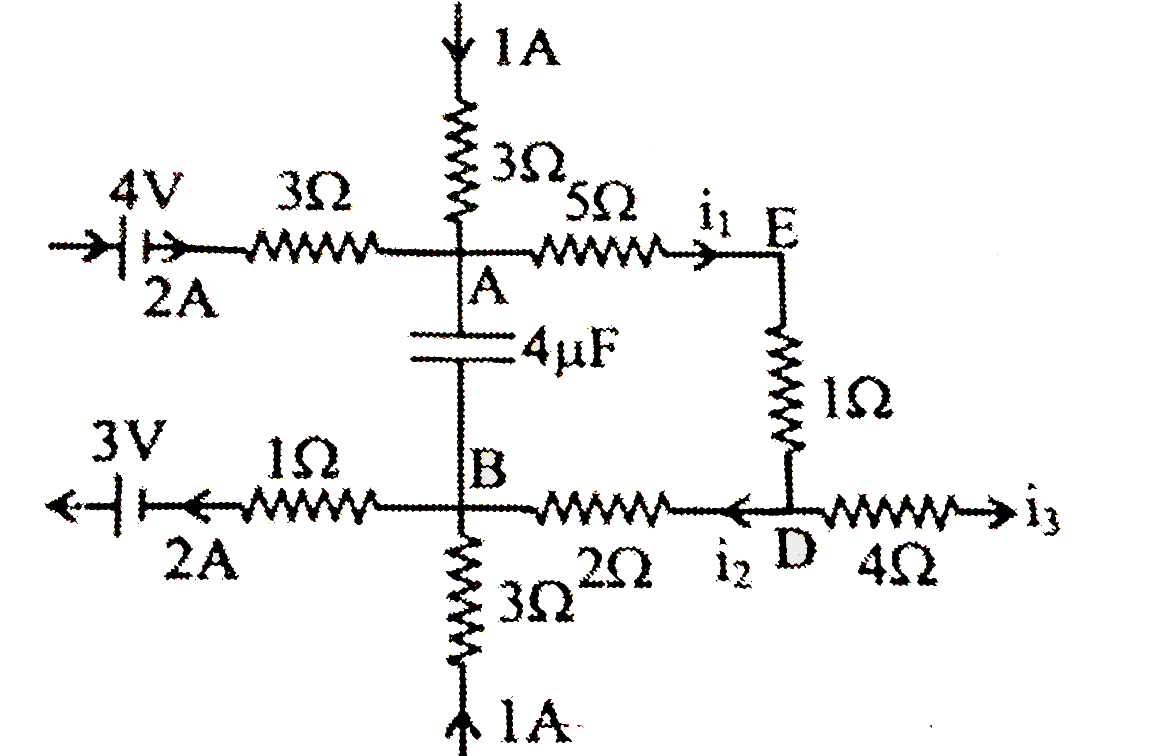
The figure shows a part of the circuit in the steady state. The currents, the valuces of resistances and emfs of the cells are shown in the figure. The circuit also contains a capacitor of capacitance C=μF. The value of i1 is-
 View Solution
