Through a uniform B field, A small rectangular loop is moving towards left with constant velocity as shown in the figure. Counting of time t begins at the moment, the loop starts entering the field.
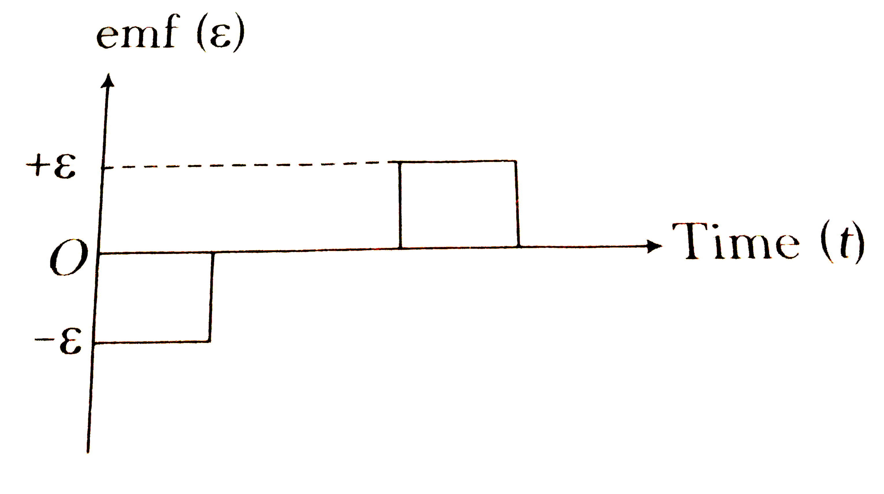
Plot the variation of flux through the loop with respect to time. Also, plot the variation of induced emf w.r.t. time t.
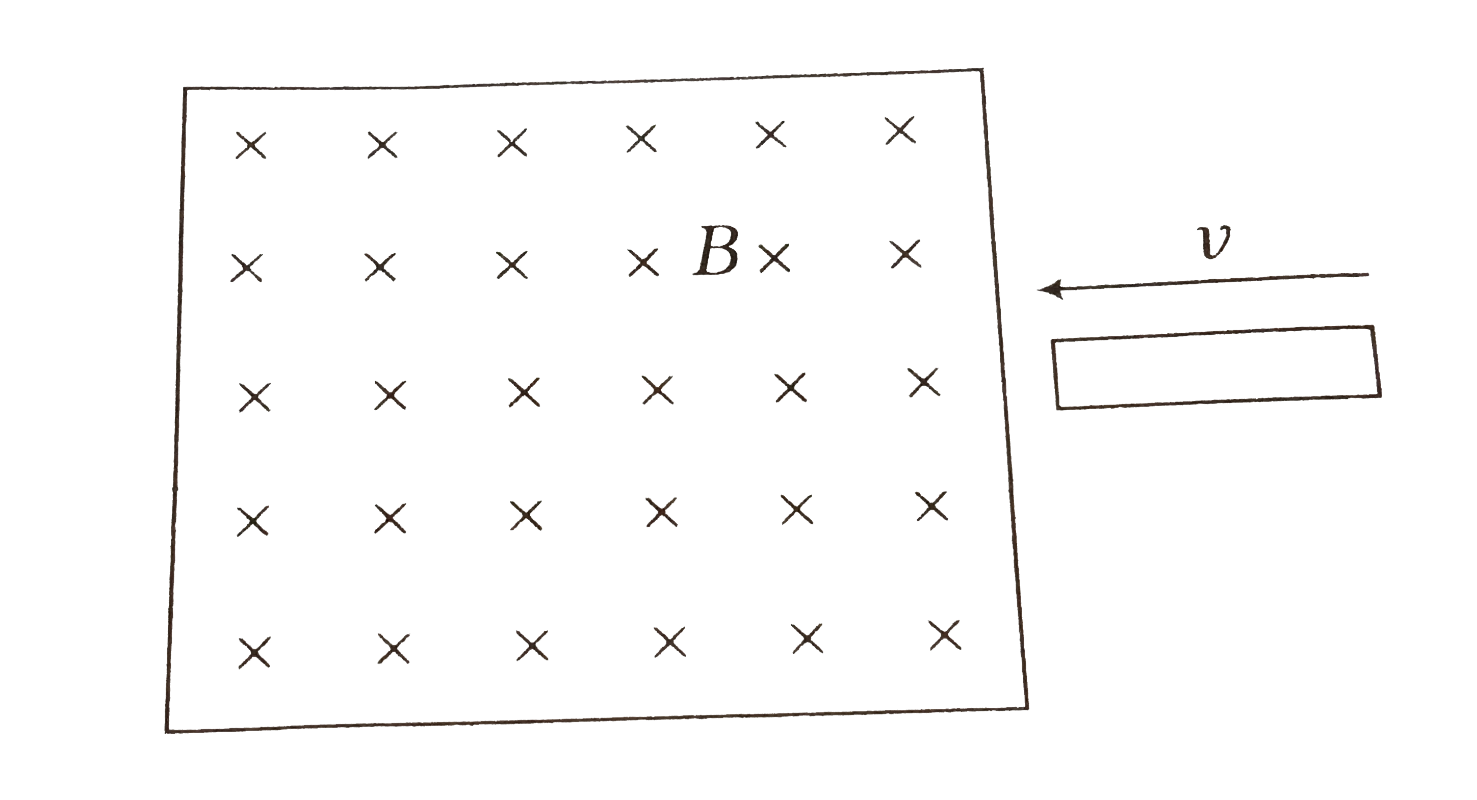
As the loop is moving with constant velocity, the flux will be increasing linearly, as long as the loop will be entering the B field. Once the loop has completely entered the B field the flux will become constant. Now, when the loop will start coming out the flux will linearly decrease to zero value.

Since, emf induced, ε=−dϕdt, it means emf is negative of the slope of the ϕ−t graph. So, emf is negative constant in the beginning, then it becomes zero and then it becomes positive constant and again it becomes zero.
Topper's Solved these Questions
- ELECTROMAGNETIC INDUCTIONBOOK - DC PANDEY ENGLISHCHAPTER - ELECTROMAGNETIC INDUCTIONEXERCISE - Check point
60 Videos
- ELECTROMAGNETIC INDUCTIONBOOK - DC PANDEY ENGLISHCHAPTER - ELECTROMAGNETIC INDUCTIONEXERCISE - Taking it together
119 Videos
- ELECTROMAGNETIC INDUCTIONBOOK - DC PANDEY ENGLISHCHAPTER - ELECTROMAGNETIC INDUCTIONEXERCISE - Level 2 Subjective
20 Videos
- CURRENT ELECTRICITYBOOK - DC PANDEY ENGLISHCHAPTER - CURRENT ELECTRICITYEXERCISE - Medical entrances gallery
97 Videos
- ELECTROMAGNETIC WAVESBOOK - DC PANDEY ENGLISHCHAPTER - ELECTROMAGNETIC WAVESEXERCISE - Sec C
22 Videos
Similar Questions
A triangular loop as shown in the figure is started to being pulled out at t=0 form a uniform magnetic field with a constant velocity v. Total resistancee of the loop is constant and equal to R. Then the variation of power produced in the loop with time will be :

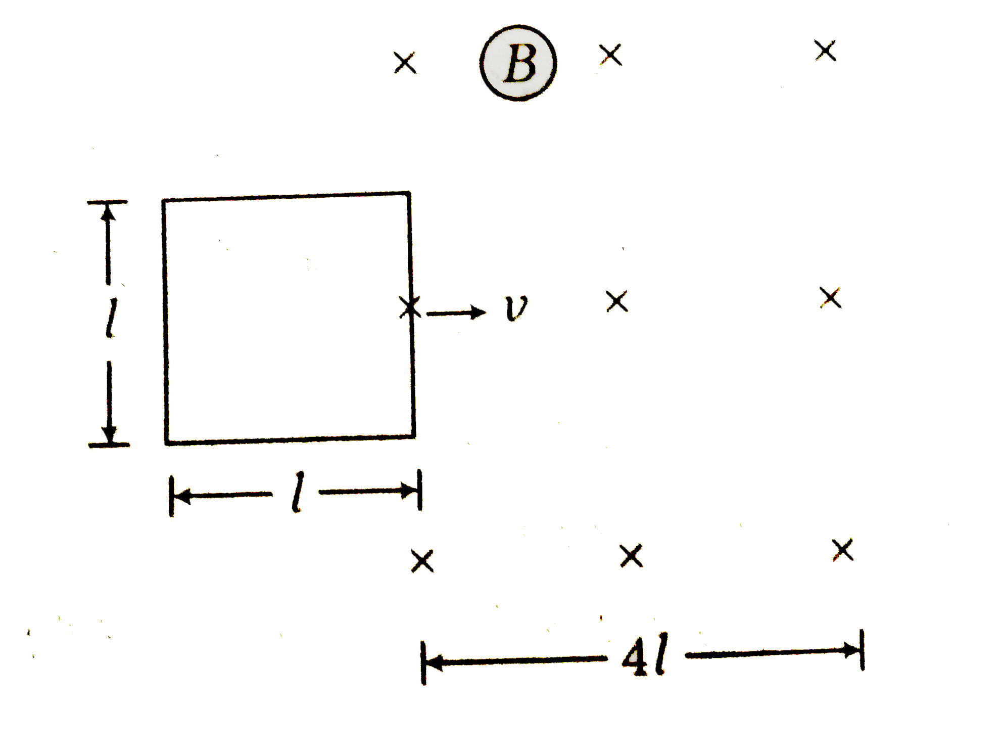
View SolutionA square loop of side l being moved towards right at a constant speed v as shown in figure. The front edge enters the magnetic field B at t = 0. The width of field is 4l. Sketch induced emf versus time graph.
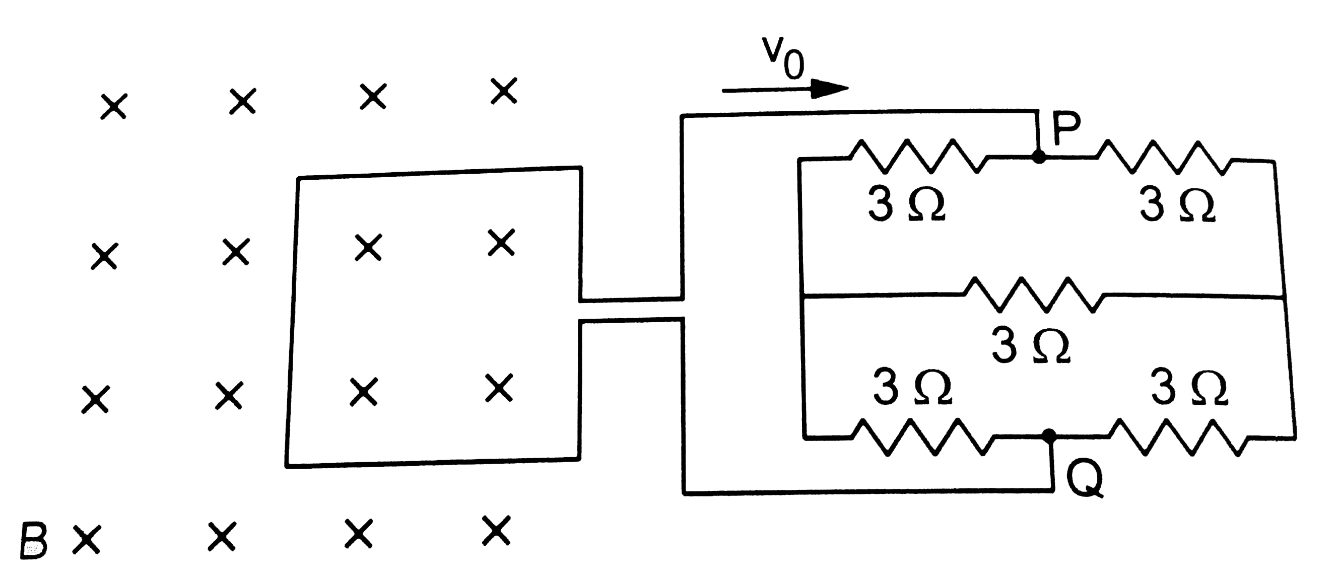
View SolutionA square loop of side 10 cm and resistance 1 Omega is moved towards right with a constant velocity V_0 as shown in . The left arm of the loop is in a uniform magnetic field of 2 T. the field is perpendicular ot the plane of the drawing and is going into it. the loop is connected to a network of resistors each of value 3 Omega with what speed should the loop be moved so that a steady curfrent of 1 mA flows in the loop.
View SolutionA horizontal loop abcd is moved across the pole piece of a magnet as shown in the figure. With a constant speed v. When the edge ab of the loop enters the pole pieces at time t=0 sec. Which one of the following graphs presents correctly the induced emf in the coil?

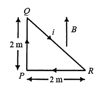
View SolutionA loop PQR carries a current i=2A as shown in the figure. A uniform magnetic field B = 2T exists in space parallel to the plane of the loop . The magnetic torque on the loop is
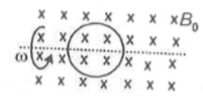
View SolutionA circular loop of radius 'a' is rotated in a uniform magnetic field B, with constant angular velocity o about diameter as shown in the figure. Choose the correct graph of induced emf & versus time t. (consider at t = 0 area vector of loop is in the direction of magnetic field)
View SolutionA rectangular loop and a circular loop are moving out of a uniform magnetic field to a field-free region with a constant velocity 'v' as shown in the figure . Explain the which loop do you expect the induced emf to the constant during the passage out of the field region . The magnetic field is normal to the loops .
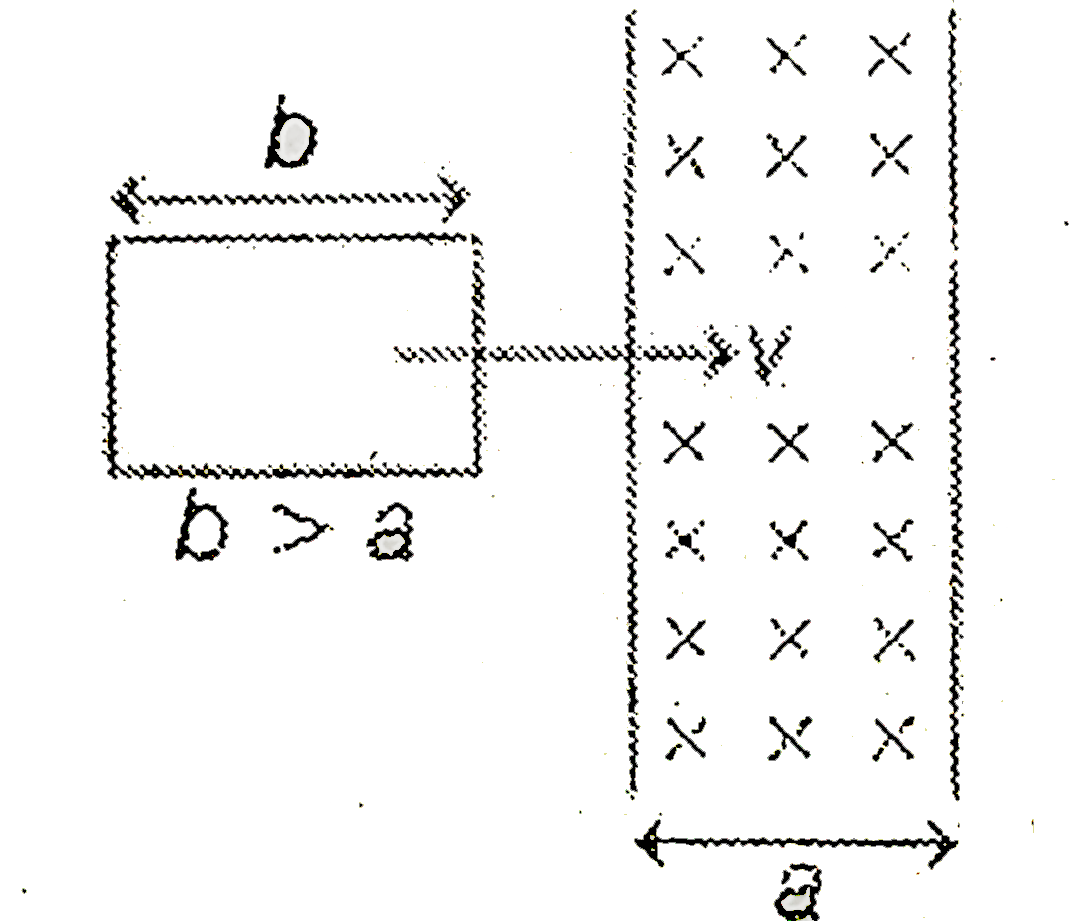
View SolutionIn the given arrangement, the loop is moved with consisant velocity in uniform magnetic field B in a restricted a region of width a. The time for which the emf is induced in the cirucit is
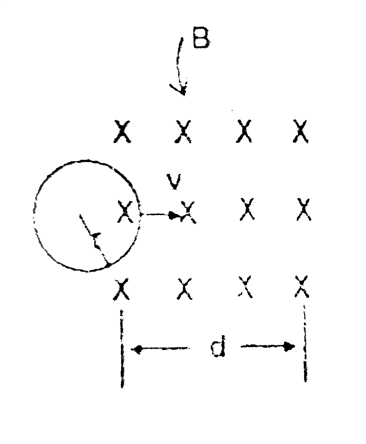
View SolutionA conducting loop is pulled with a constant velocity towards a region of unifrom maganetic field of induction B as shown in the figure. Then the current involved in the loop is (d>r)
View SolutionA square loop of side b is rotated in a constant magnetic field B at angular frequency ω as shown in the figure. What is the emf induced in it?
View Solution
