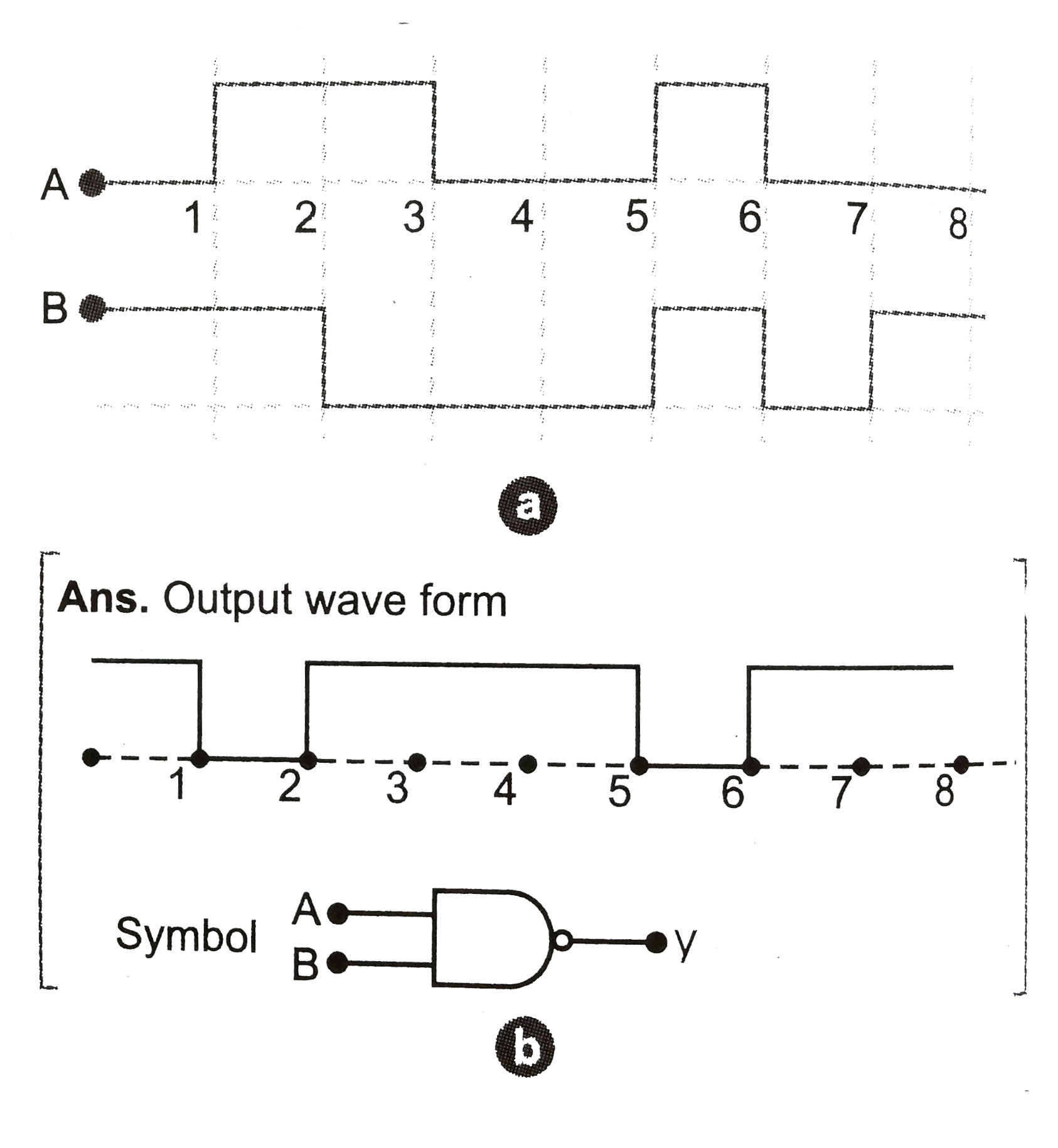
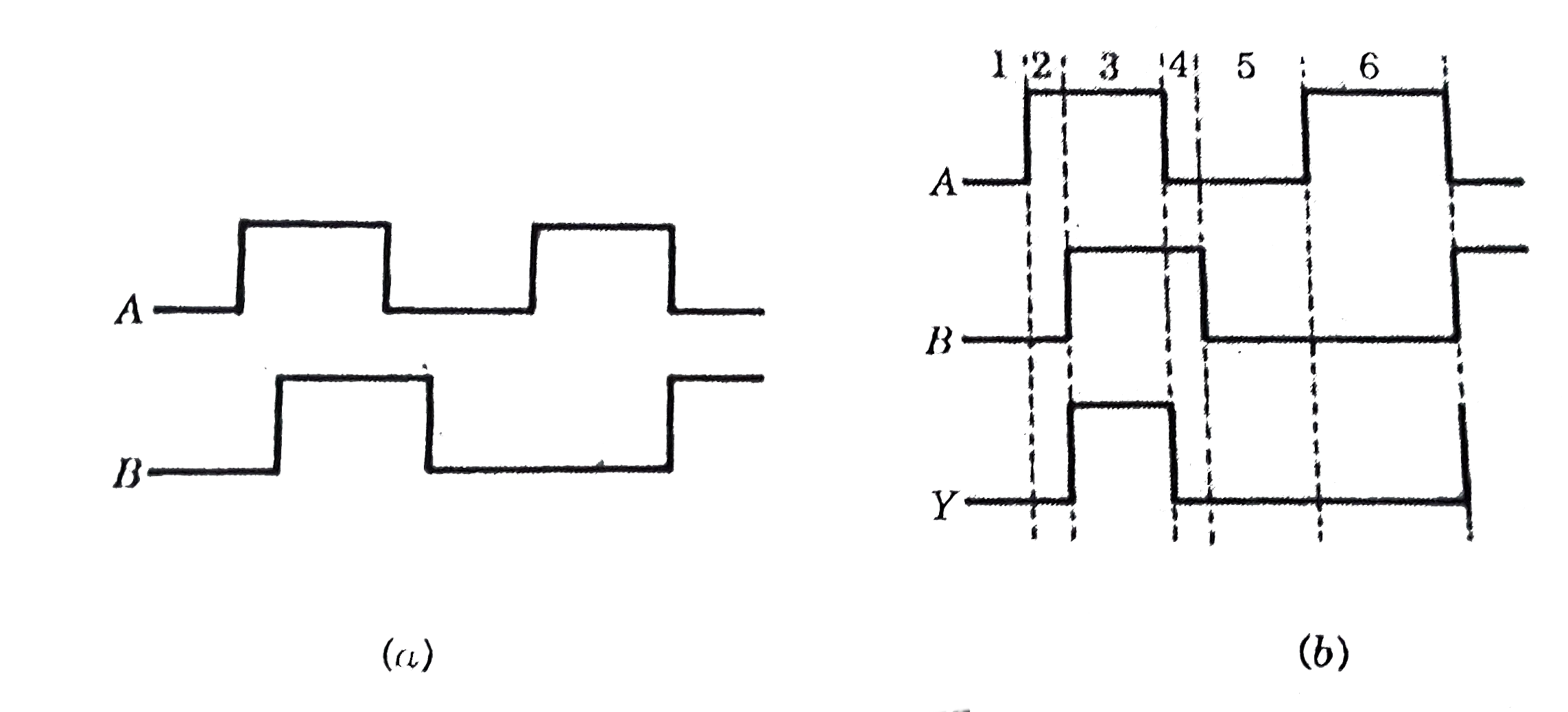
Two signals A, and B shown in Fig. are used as two inputs of an AND gate obtain its output wave form. Draw the logic symblo of AND gate.
Video Solution
Text Solution
For AND gate, output y=A.B and for NAND gate y1=¯¯¯¯¯¯¯¯A.B.
For time less than 1, A=0,B=1,y=0,y1=1
For time 1 to 2, A=1,B=1,y=1,y1=0
For time 2 to 3, A=1,B=0,y=0,y1=1
For time 3 to 4, A=0,B=0,y=0,y1=1
For time 4 to 5, A=0,B=0,y=0,y1=1
For time 5 to 6, A=1,B=1,y=1,y1=0
For time 6 to 7, A=0,B=0,y=0,y1=1
For time 7 to 8, A=0,B=1,y=0,y1=1
|
Topper's Solved these Questions
- ELECTRONIC DEVICESBOOK - PRADEEPCHAPTER - ELECTRONIC DEVICESEXERCISE - LONG QUESTION ANSWER
2 Videos
- ELECTRONIC DEVICESBOOK - PRADEEPCHAPTER - ELECTRONIC DEVICESEXERCISE - PROBLEMS FOR PRACTICE
7 Videos
- ELECTRONIC DEVICESBOOK - PRADEEPCHAPTER - ELECTRONIC DEVICESEXERCISE - HIGHER ORDER THINKING SKILLS
1 Videos
- ELECTROMAGNETIC WAVESBOOK - PRADEEPCHAPTER - ELECTROMAGNETIC WAVESEXERCISE - II Focus multiple choice question
5 Videos
- ELECTROSTATICSBOOK - PRADEEPCHAPTER - ELECTROSTATICSEXERCISE - ASSERTION-REASON TYPE QUESTIONS
2 Videos
Similar Questions
Knowledge Check
If A and B are two inputs in AND gate, then AND gate has an output of 1 when the values of A and B are
AA=0,B=0BA=1,B=1CA=1,B=0DA=0,B=1If A and B are two inputs in AND gate, then AND gate has an output of 1 when the values of A and B are
AA=0,B=0BA=1,B=1CA=1,B=0DA=0,B=1The real time variation of input signals A and B are as shown below. If the inputs are fed into NAND gate, then select the output signal from the following :-
_E01_434_Q01.png) A
A_E01_434_O01.png) B
B_E01_434_O02.png) C
C_E01_434_O03.png) D
D_E01_434_O04.png)
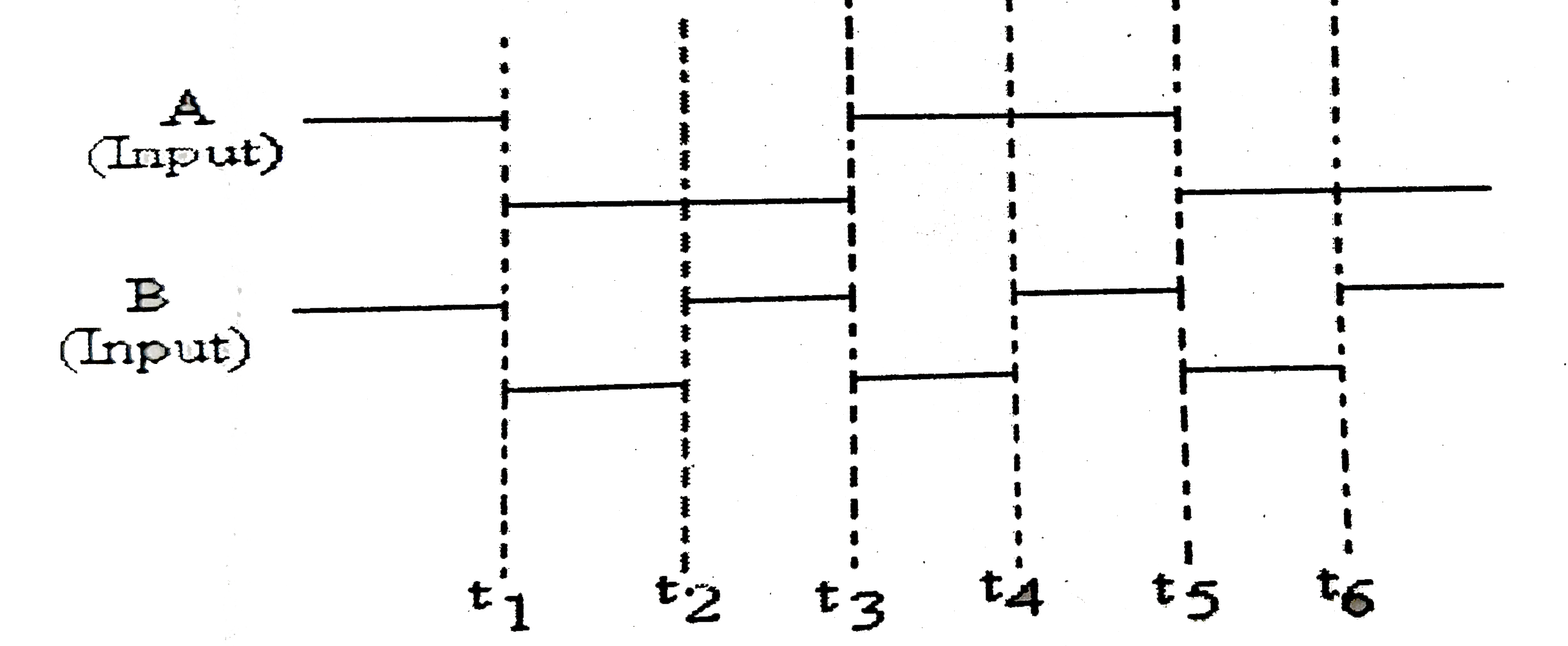
The give inputs A, B are fed to a 2-input NAND gate. Draw the output wave form of the gate.
View SolutionThe input wave form for NOT gate is shown in Fig.Draw the output wave form of this gate.
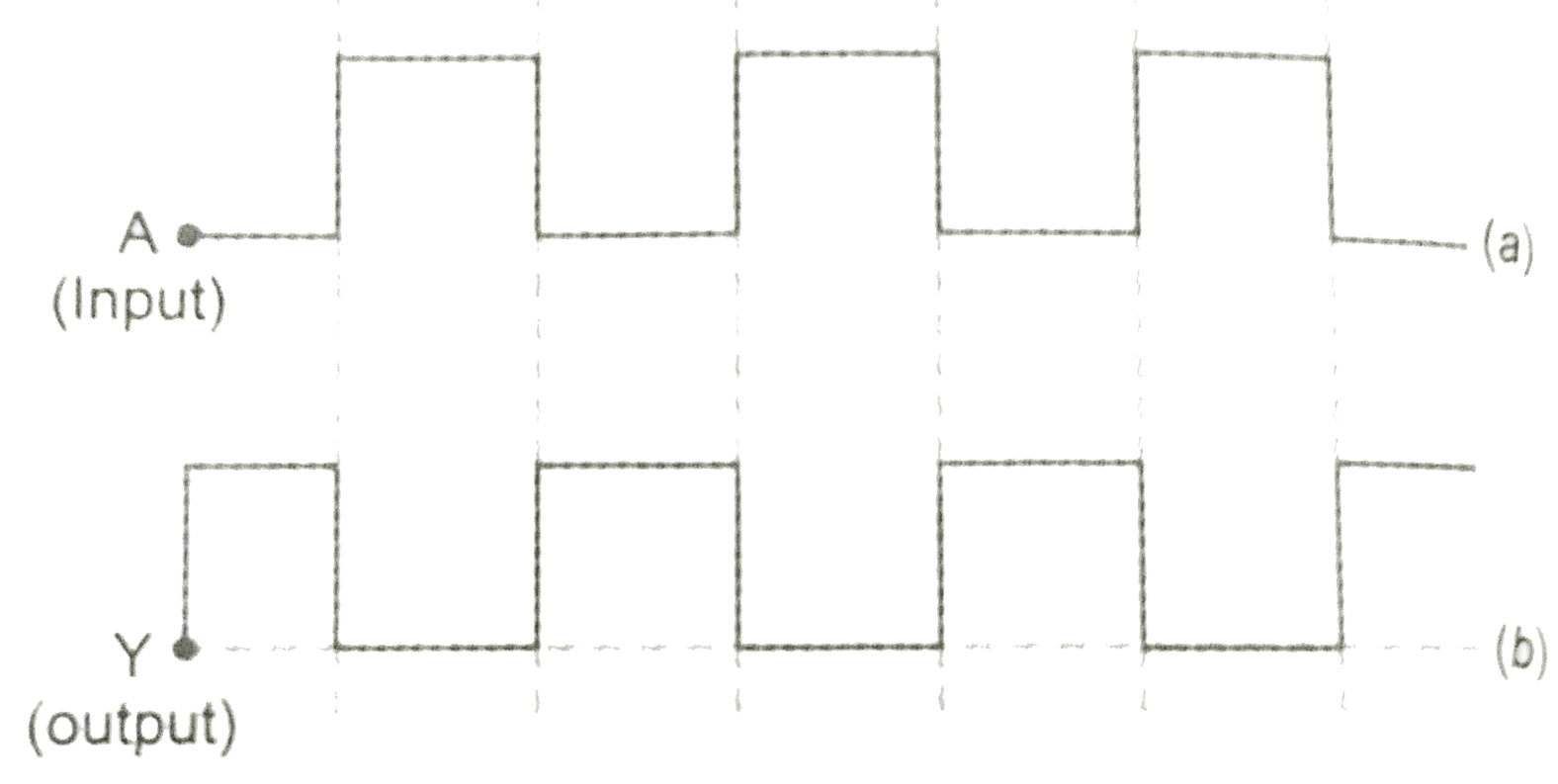
View SolutionTwo signals A, B as given below are applied to (i) AND (ii) NOR and (iii) NAND gates. Draw the output wave form in each case.
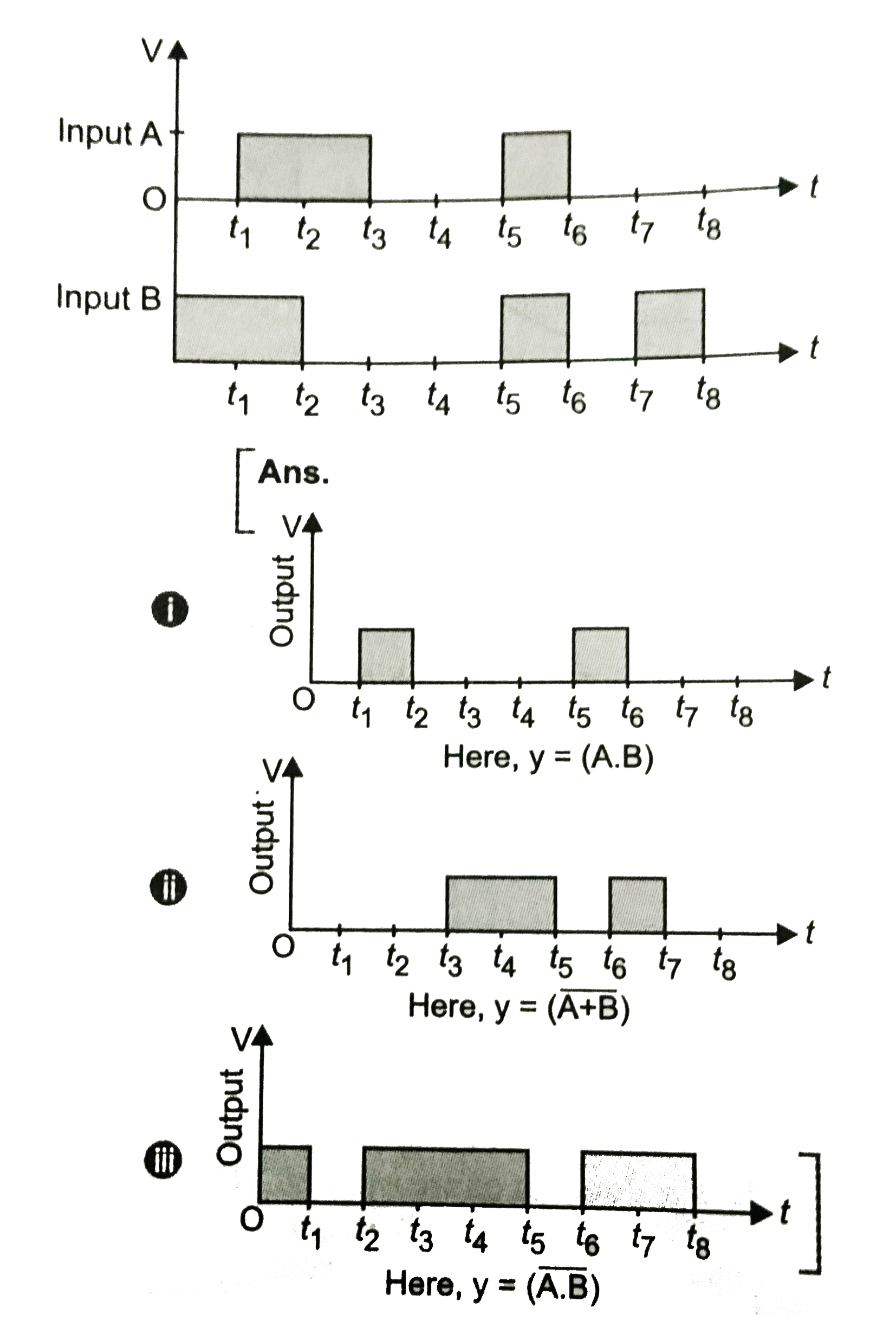
View SolutionThe Fig.shows the input wavwforms A and B for 'AND' gate. Draw the output waveform and write the truth table for this logic gate.
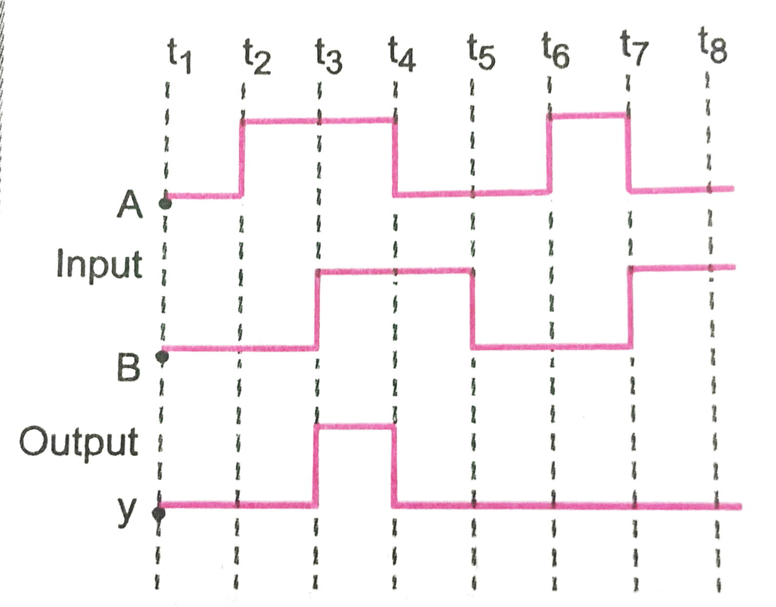
View SolutionIf A and B are two inputs in OR gate , then OR gate has an output of 0 when the value of A and B are
View Solution

