Variation of current passing through a conductor as the voltage applied across its ends is varied as shown in the adjoining diagram. If the resistance (R) is determined at the points A, B, C and D, we will find that
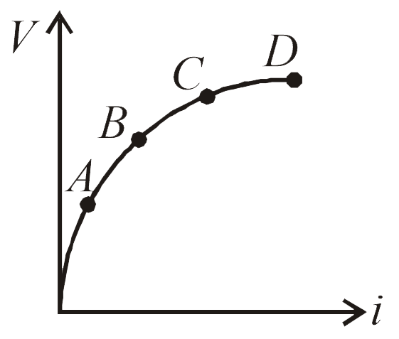
RC=RD
RB>RA
RC>RB
None of these
The correct Answer is:D
Step by step video & image solution for Variation of current passing through a conductor as the voltage applied across its ends is varied as shown in the adjoining diagram. If the resistance (R) is determined at the points A, B, C and D, we will find that by Physics experts to help you in doubts & scoring excellent marks in Class 12 exams.
Updated on:21/07/2023Topper's Solved these Questions
- ELECTRIC CURRENT & CIRCUITSBOOK - CENGAGE PHYSICS ENGLISHCHAPTER - ELECTRIC CURRENT & CIRCUITSEXERCISE - Combination of Resistance 1
14 Videos
- ELECTRIC CURRENT & CIRCUITSBOOK - CENGAGE PHYSICS ENGLISHCHAPTER - ELECTRIC CURRENT & CIRCUITSEXERCISE - Combination of Resistance 2
14 Videos
- COULOMB LAW AND ELECTRIC FIELDBOOK - CENGAGE PHYSICS ENGLISHCHAPTER - COULOMB LAW AND ELECTRIC FIELDEXERCISE - Single Answer Correct Type
22 Videos
- ELECTRIC CURRENT AND CIRCUITBOOK - CENGAGE PHYSICS ENGLISHCHAPTER - ELECTRIC CURRENT AND CIRCUITEXERCISE - Interger
8 Videos
Similar Questions
For a given metallic conductor , the variation of current through the conductor with potential difference applied across the conductor is shown in the given graph. If temperature of the conductor is increased , then slope tan theta
_PHY_E01_0010_Q01.png)
View SolutionCurrent passing through a resistor of resistance 5Ω varies with time as shown in the graph.Heat generated in the resistance during 3s is equal to
_PHY_E05_283_Q01.png)
View Solution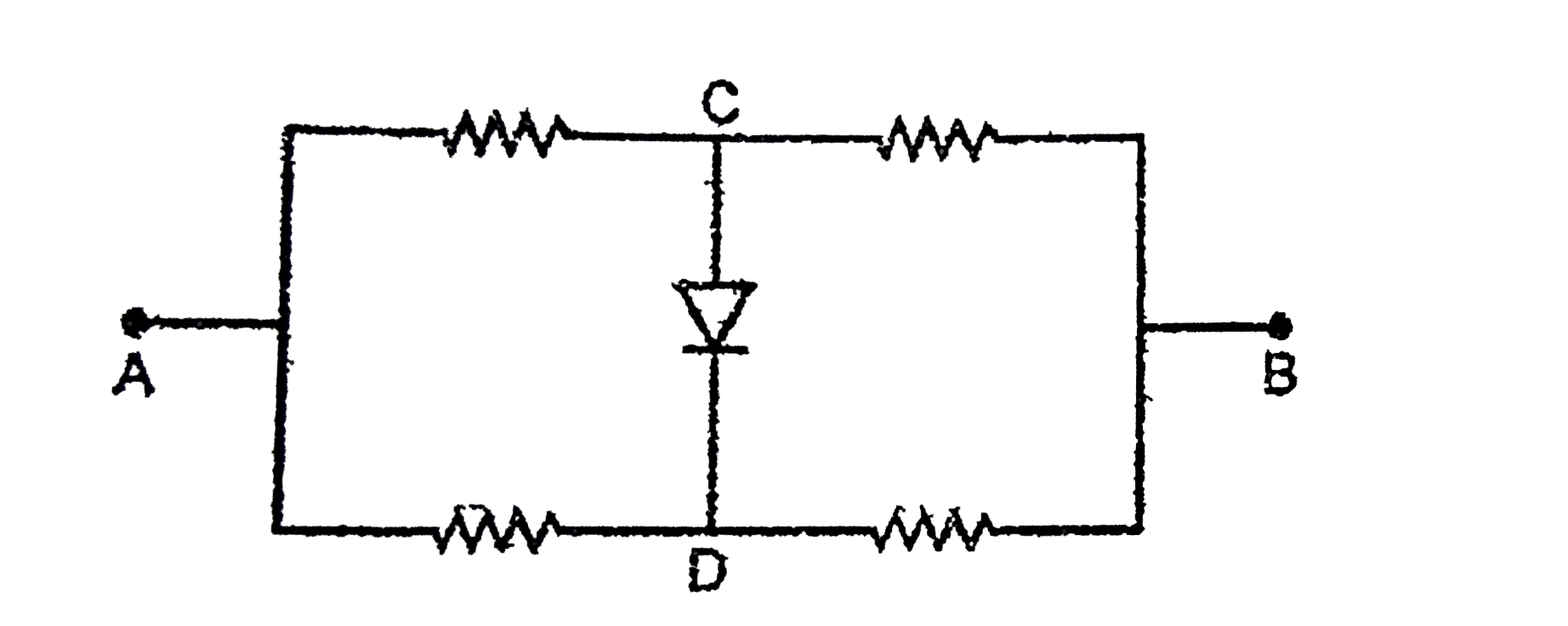
Four equal resistors, each of resistance 10 ohm are connected as shown in the adjoining circuit diagram. Then the equivalent resistance between points A and B is-
View SolutionIn an electric circuit shown alongside, find
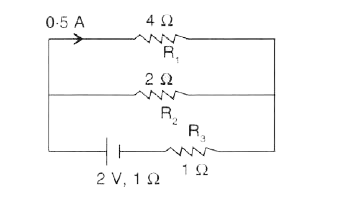
terminal voltage of the battery
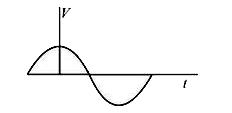
View SolutionVoltage across a capacitor varies as shown in the diagram. Which diagram correctly represents the current time curve?
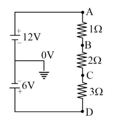
View SolutionIn the circuit diagram shown in Figure , the potentials of the points B, C and D are respectively -
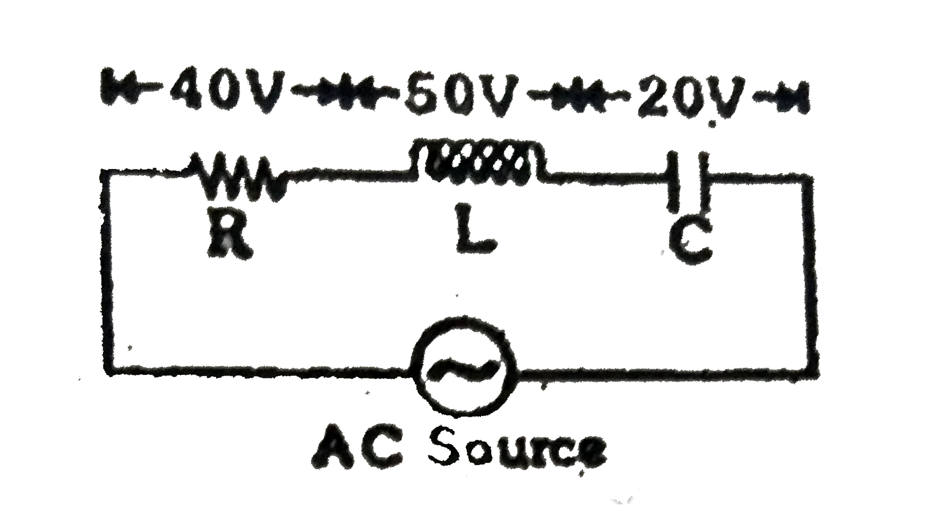
View SolutionIn series LCR circuit, the voltages across R, L and C are shown in the figure. The voltage of applied source
View Solution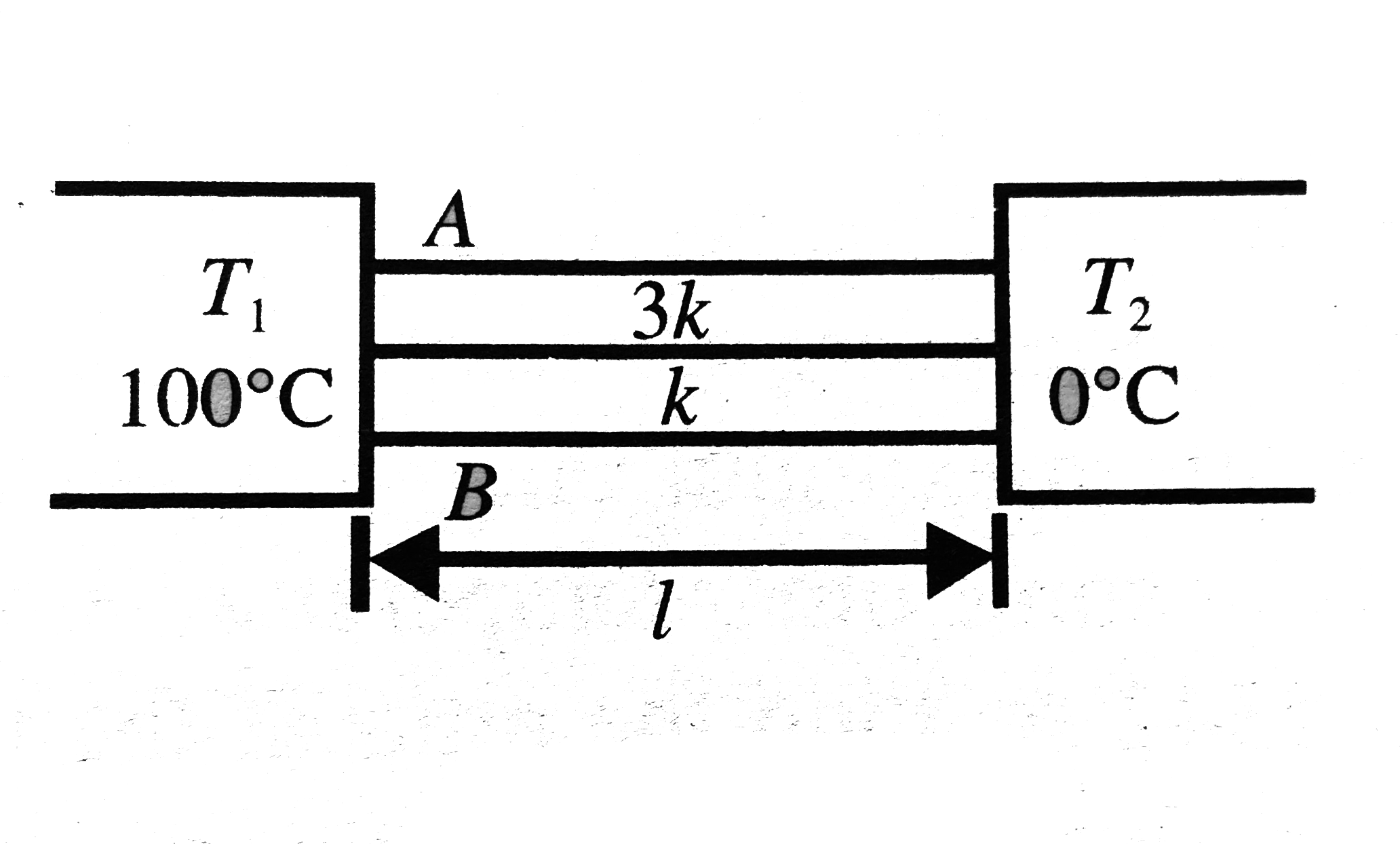
Two conductors A and B are connected in parallel as shown in Fig.
i. Determine the equivalent thermal resistance.
ii. Determine the heat current in each rod.
View SolutionCalculate the current through the resistance connected across MN and the current supplied by each of the batteries in the circuit diagram shown in

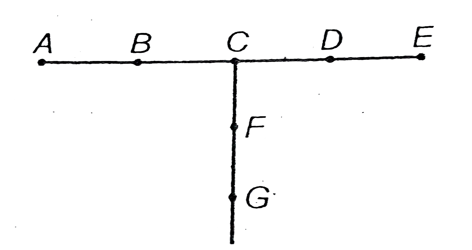
View SolutionThe number of different circles passing through the points A,B,C,D,E,F and G as shown in the adjacent figure.
View Solution
