Complete Solutions to Multiple Choice Questions of chapter THE HUMAN EYE AND THE COLOURFUL WORLD of Class 10 book with complete answers and questions
| Class 10 | PHYSICS |
| Chapter | THE HUMAN EYE AND THE COLOURFUL WORLD |
| LAKHMIR SINGH & MANJIT KAUR | Multiple Choice Questions |
| Number Of Questions | 100 |
| Academic Year | 2023-24 |
A person got his eyes tested. The optician's prescription for the spectacles reads :
Left eye : - 3.00 D `" "` Right eye : - 3.50 D
The person is having a defect of vision called :
View SolutionThe animal which does not have eyes that look sideways is :
View SolutionThe animal of prey have :
View SolutionThe animals called predators have :
View SolutionWhich of the following coloured light has the least speed in glass prism ?
View SolutionThe stars twinkle but the planets do not twinkle at the night because :
View SolutionTo study the dependence of current (I) on the potential difference (V) across a resistor, the correct way of connecting the ammeter and voltmeter in the circuit is :
View SolutionThe following four circuits have been made for studying the dependence of current on the potential difference across a resistor.
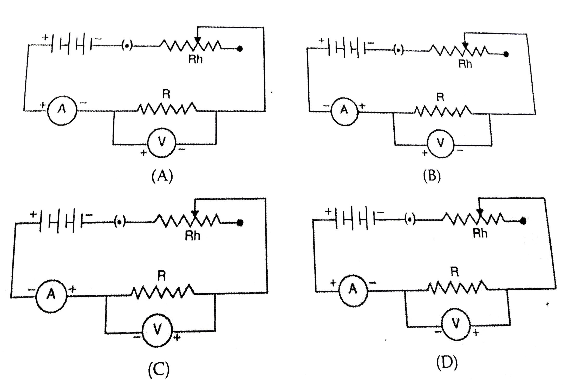
The correct circuit is :
View SolutionTo study the dependence of current (I) on the potential difference (V) across a resistor, the following observations were made by four students A, B, C and D.
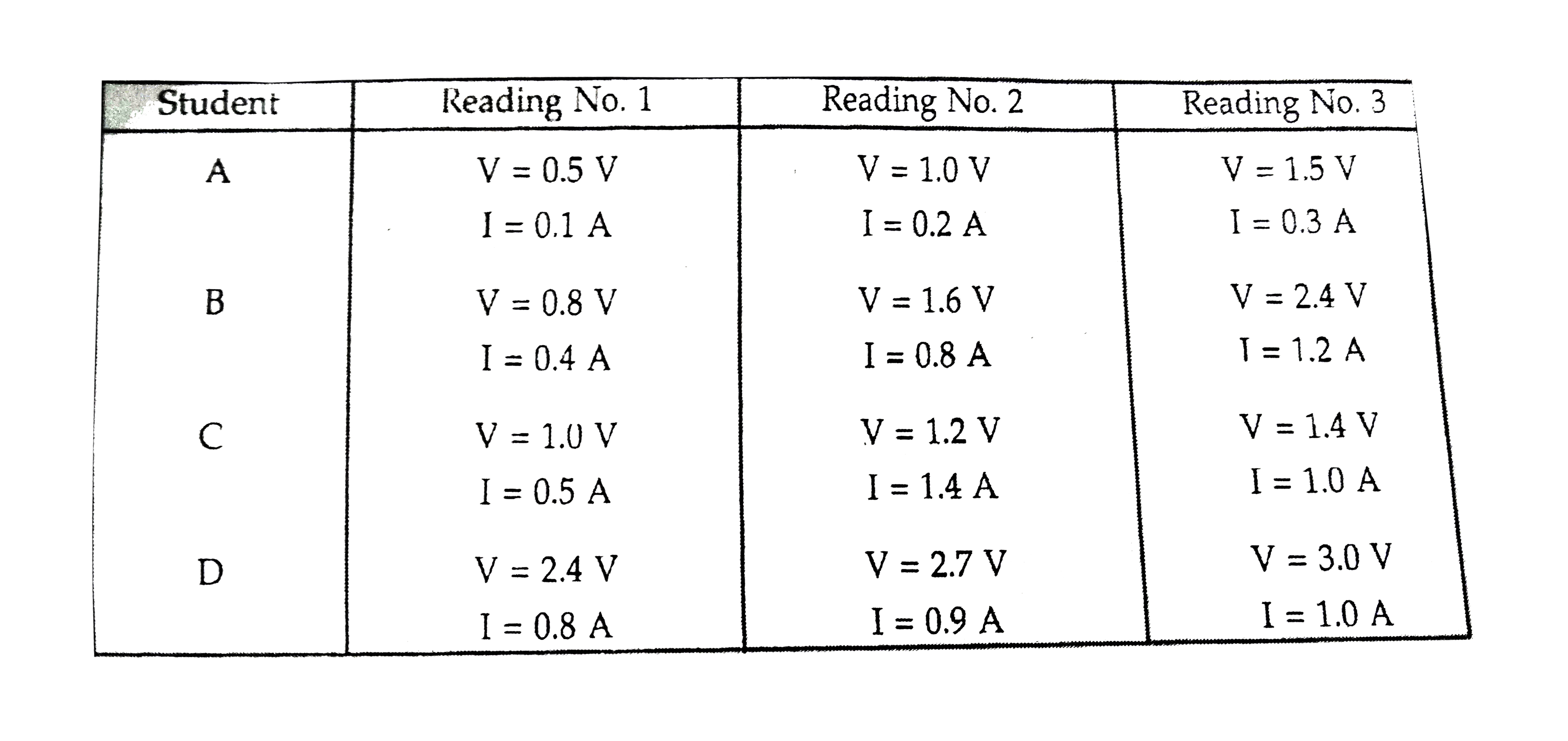
The teacher found that one of the students has made wrong observations. The student who made the mistake is :
View SolutionThe following 'precautions' were listed by a student in the experiment on study of 'Dependence of current on potential difference'.
(A) Use copper wires as thin as possible for making connections.
(B) All the connections should be kept tight.
(C) The positive and negative terminals of the voltmeter and the ammeter should be correctly connected.
(D) The 'zero error' in the ammeter and the voltmeter should be noted and taken into consideration while recording the measurements.
(E) The 'key' in the circuit, once plugged in, should not be taken out till all the observations have been completed.
The 'precautions' that need to be corrected and revised are :
View SolutionAn ammeter has 20 divisions between 0 A mark and 2 A mark on its scale. The least count of this ammeter is :
View SolutionA student finds that there are 20 divisions between the 0 mark and 1 V mark of a voltmeter. What is the least count of this voltmeter ?
View SolutionWhich of the following instruments does not have plus (+) or minus (-) sign marked on it while representing in a circuit diagram ?
View SolutionTo study the dependence of current (I) on the potential difference (V) across a resistor R, two students used the two set ups shown in Figures A and B respectively. They kept the contact point J in four different positions, marked (a), (b), (c) and (d) in the two figures.

For the two students, the ammeter and voltmeter readings will be maximum when the contact J is in the position :
View SolutionIn the circuit given below, the instrument B reads 0.93 and the instrument A reads 1.80 in their respective SI units.
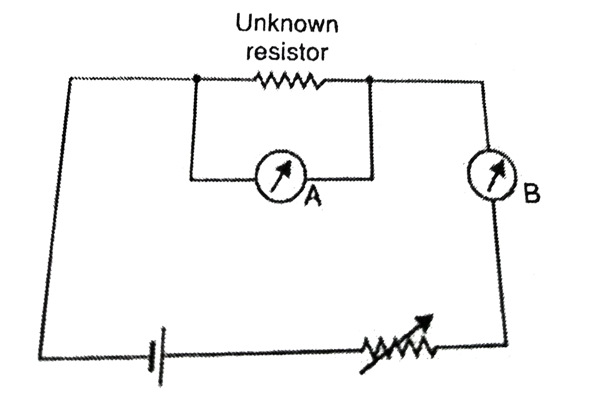
The value of unknown resistor will be :
View SolutionFour identical cells of emf 1.5 V each were connected in four different ways as shown below :

The potential difference between the points X and Y would be equal to 6.0 V in case/cases :
View SolutionThe scale of an ammeter is shown below :
The least count of this ammeter is
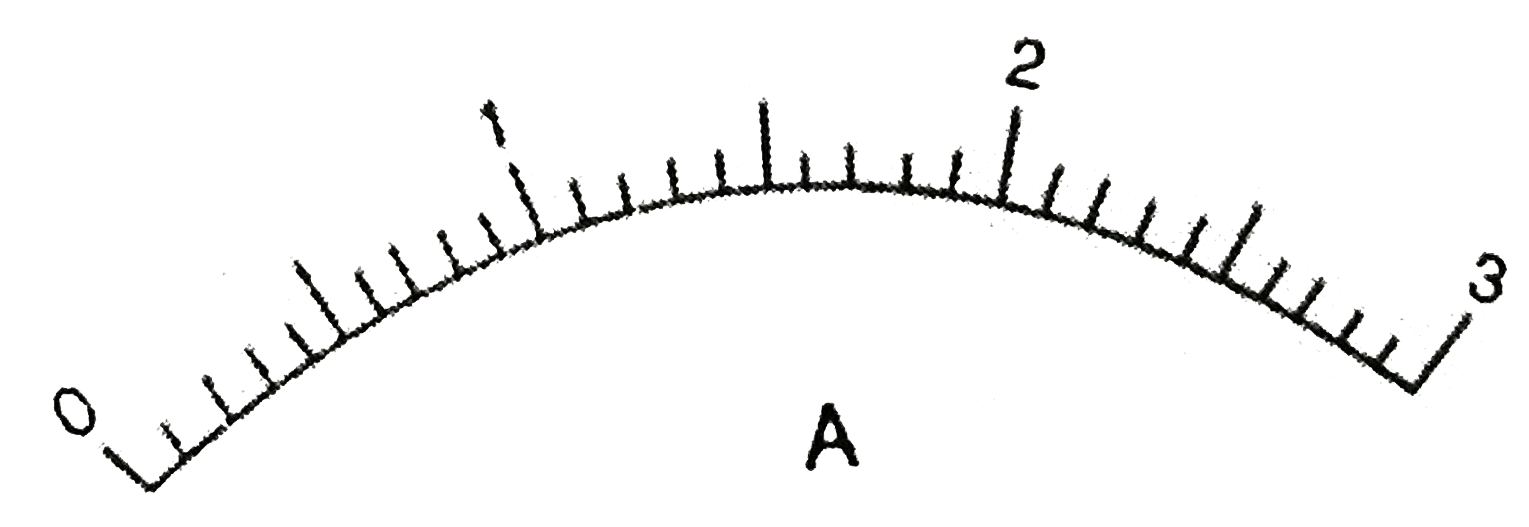 :
:
View SolutionThe least count of the voltmeter shown below is :
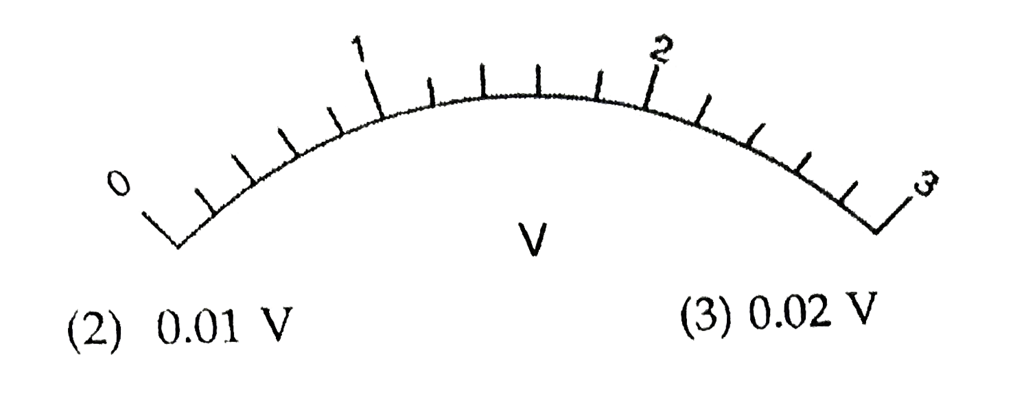
View SolutionConsider the following circuits :

On plugging the key, the voltmeter/ammeter is likely to be damaged :
View SolutionThe rest positions of the needles in a Milliammeter and Voltmeter when not being used in a circuit are as shown in the figure. The 'zero error' and 'least count' of these two instruments are :
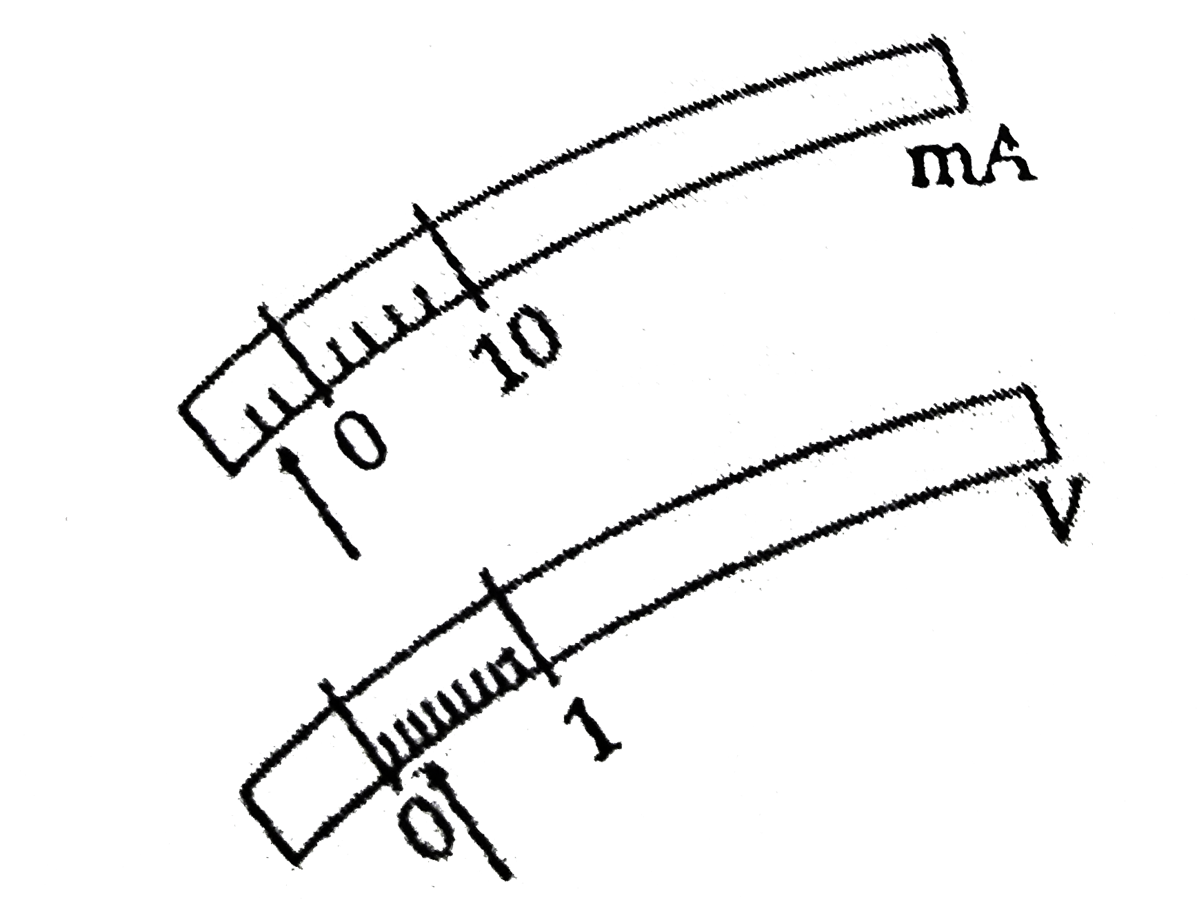
View SolutionA student has to connect 4 cells of 2 V each to form a battery of voltage 8 V. The correct way of connecting these cells is shown in figure :
View SolutionTo study the dependence of current (I) on the potential difference (V) across a resistor, two students used the two sets ups shown in figs (A) and (B) respectively. They kept the contact J in four different positions, marked (a), (b), (c), (d) in the two figures.
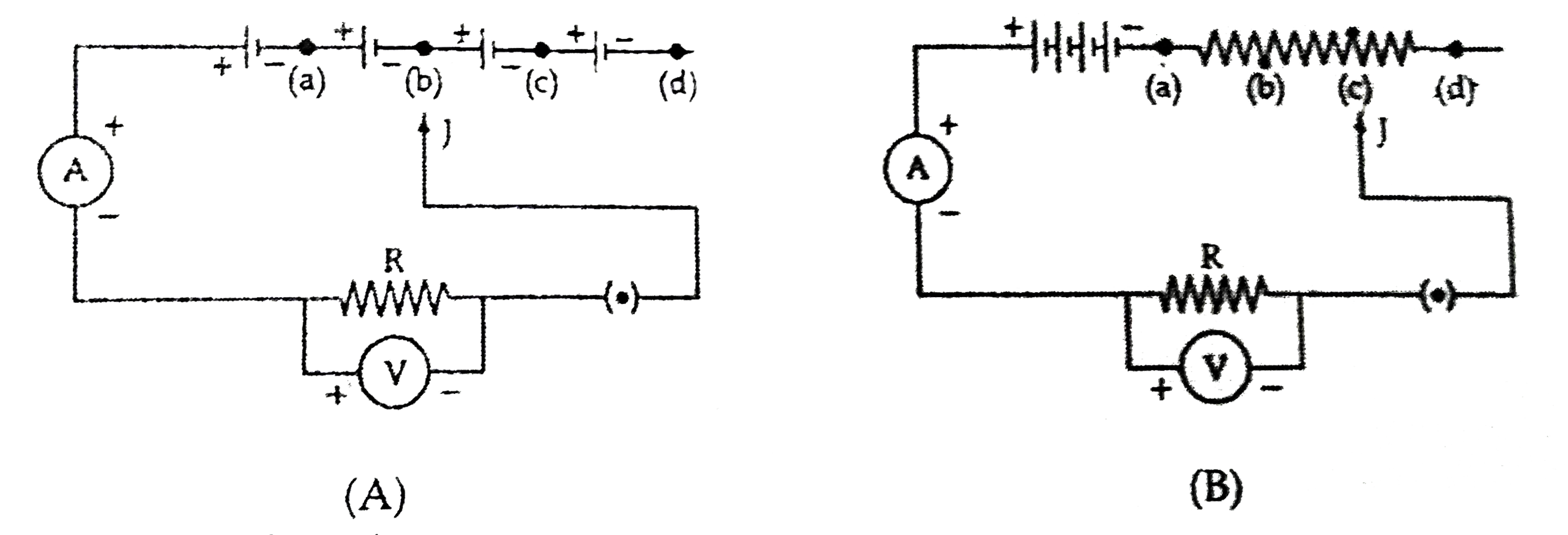
For the two students, their Ammeter and Voltmeter readings will be minimum when the contact J is in the position :
View SolutionIn the circuits A, B, C and D, with switch S open, the lamps Q and R would light up but not lamp P in :

View SolutionThe rest positions of the needles in a milliammeter and voltmeter not in use are as shown in (Fig. 3.61)(a). When a student uses these in his experiment, the readings of the needles are in the positions shown in (Fig. 3.61)(b). Find the corrected values of current and voltage in the experiment.
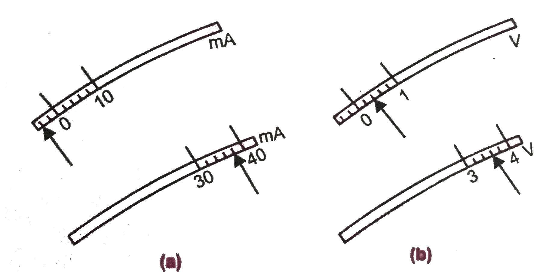 .
.
View SolutionThe current following through a resistor connected in an electric circuit and the potential difference applied across its ends are shown in the figures below :
The value of the resistance of the resistor is :

View SolutionConsider the following circuits diagrams drawn by four students :
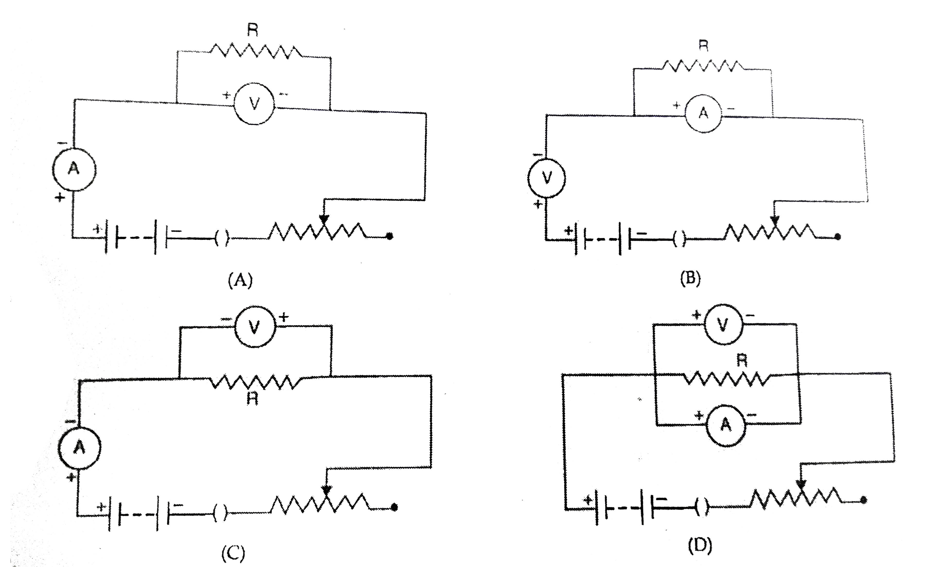
The correct circuit diagram for studying the dependence of current on the potential difference across a resistor is :
View SolutionThe scale of an ammeter is shown below :
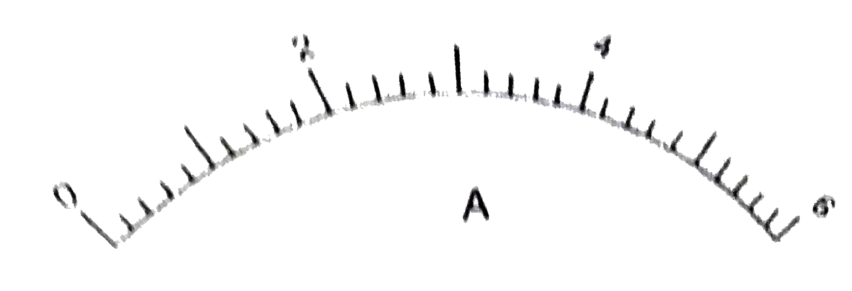
The least count of this ammeter is :
View SolutionThe figure below shows the scale of a voltmeter :
The least count of this voltmeter is :
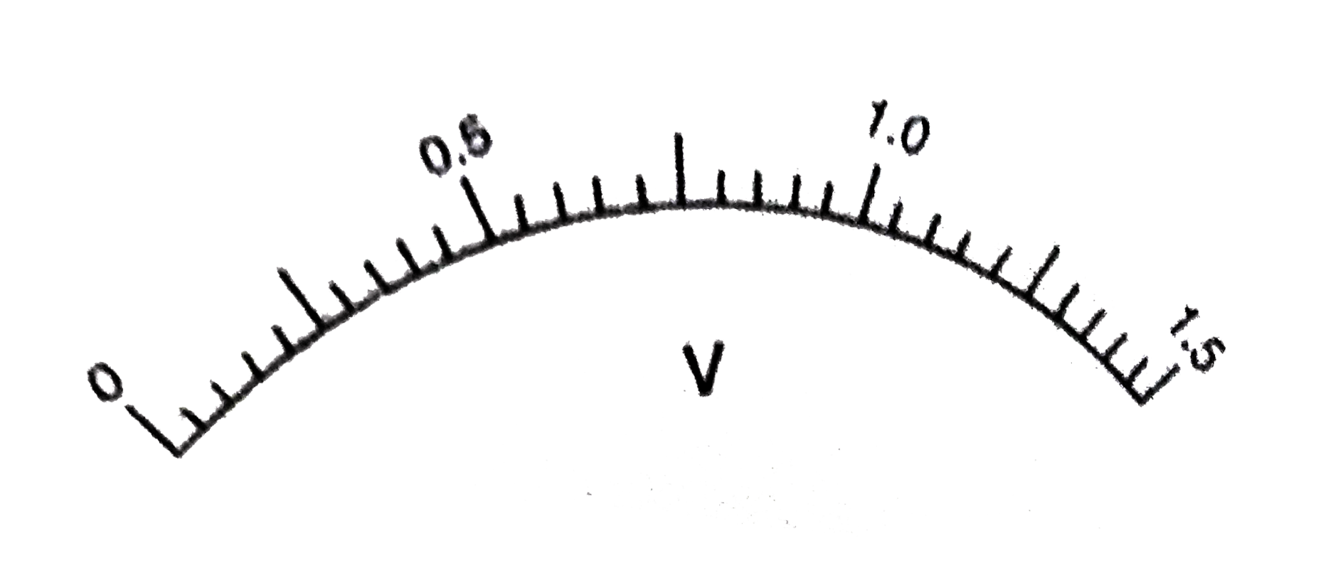
View SolutionA student used the set up given here to study the dependence of current (I) on the potential difference (V) across a resistor.
He kept the contact C in four different positions marked as P,Q,R and S in the figure. On calculating the values of the ratio `(V)/(I)` for his four readings, he would find that the value of this ratio :
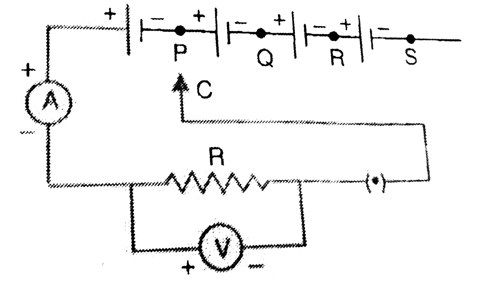
View SolutionYou are given tha following four voltmeters to study the dependence of current (I) on the potential difference (V) across a resistor.

Which one of the above voltmeters would you prefer to use in the circuit to begin your experiment ?
View SolutionA student arranged an electric circuit as shown alongside :
He would observe :
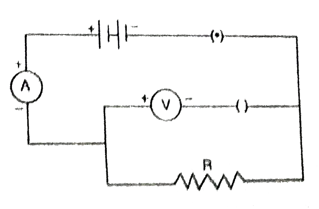
View SolutionFour students recorded the readings of the current by observing the position of pointer on the ammeter scale given below :
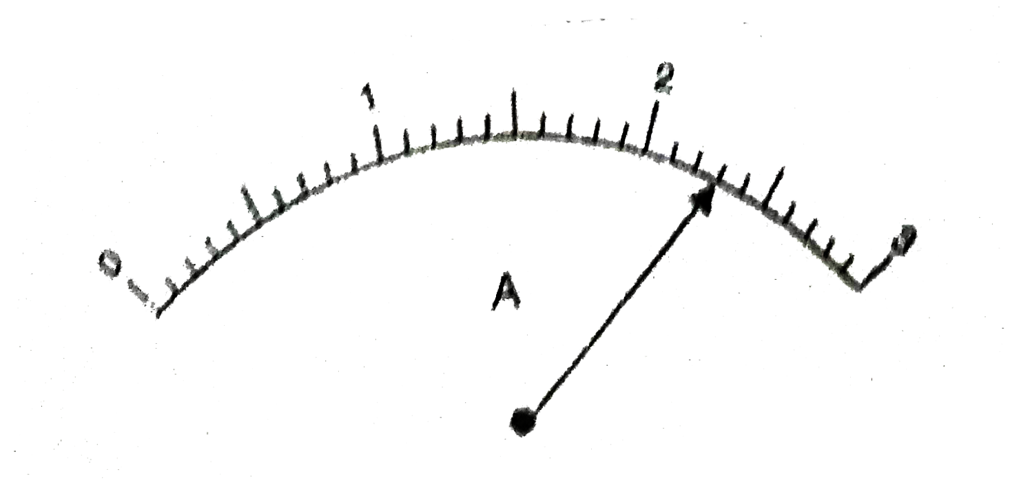
If there is no zero error, the correct reading of current is :
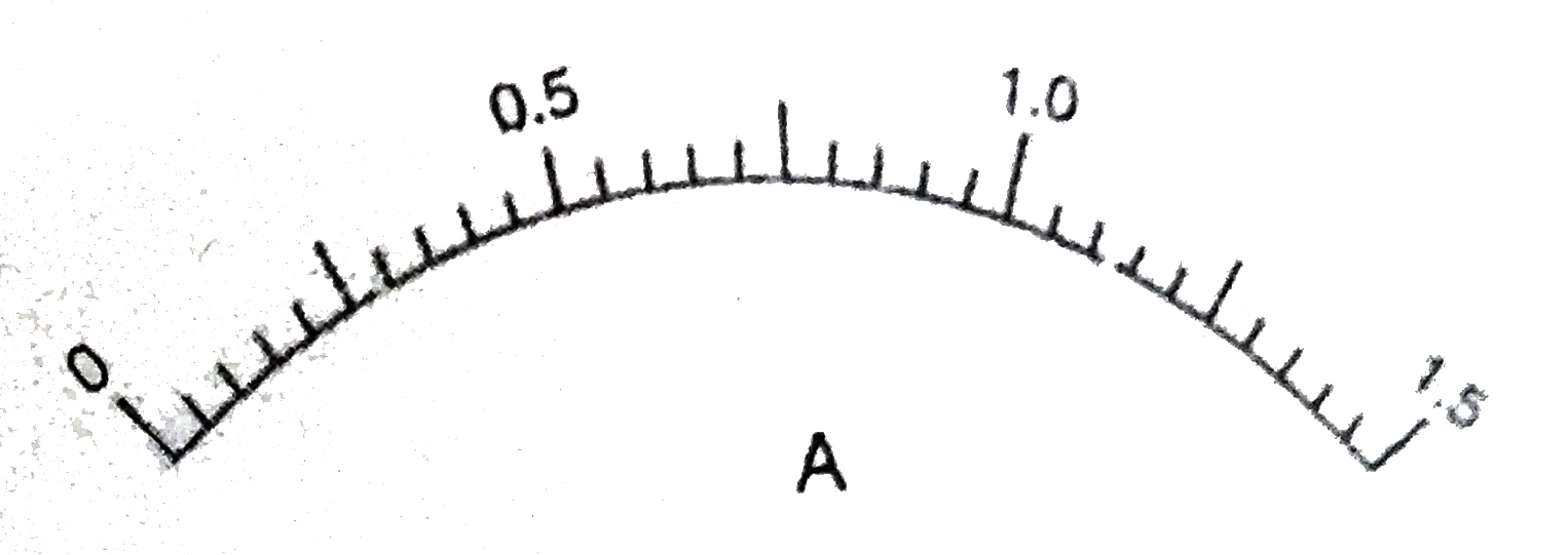
View SolutionThe least count of the ammeter shown below is :
View SolutionFour students measured the reading by observing the position of pointer on the ammeter scale as shown below :
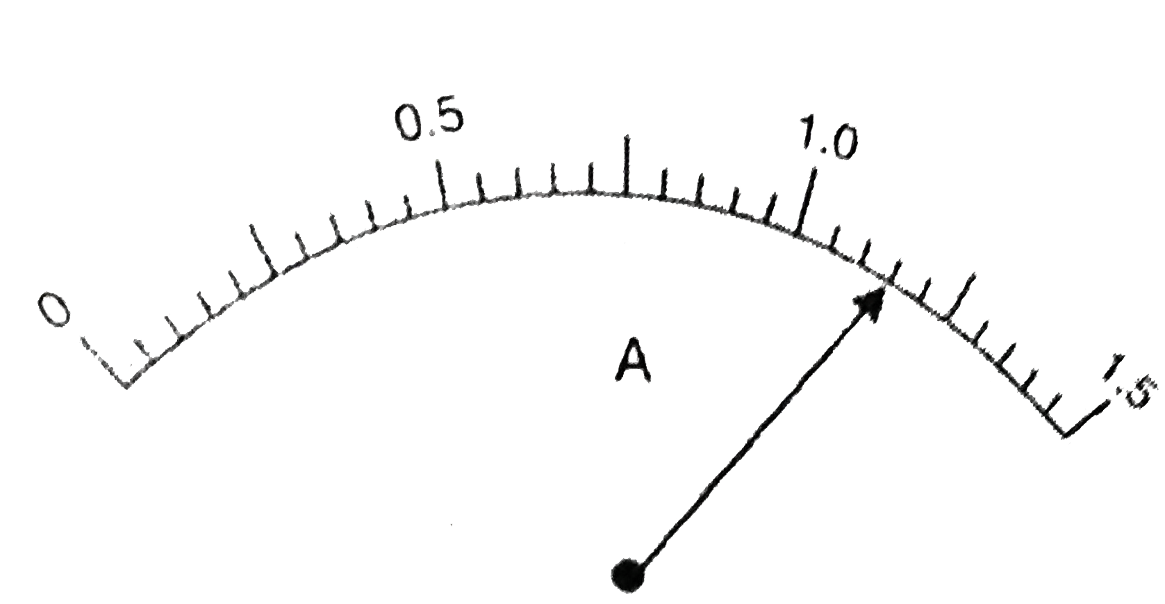
Assuming that the ammeter has no zero error, the correct reading is :
View SolutionFour students recorded the readings of the potential differece by observing the position of the pointer of an ideal voltmeter as shown below :
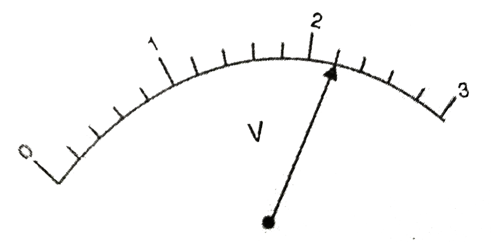
The correct reading is :
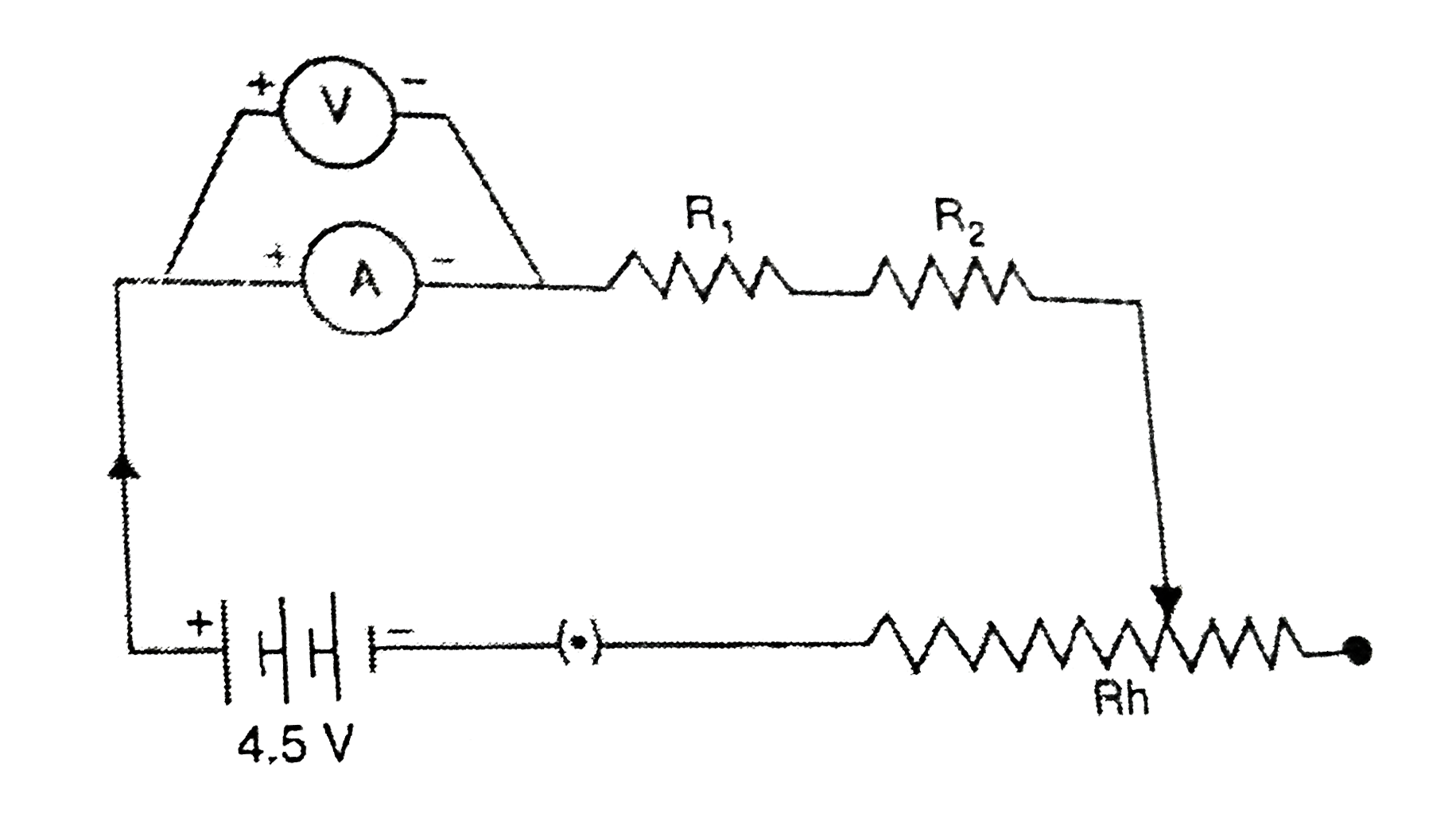
View SolutionIn an experiment to find the equivalent resistance of two resistors connected in series, a student uses the circuit shown :
This circuit will give :
View SolutionA student stes up an electric circuit shown here for finding the equivalent resistance of two resistors in series :
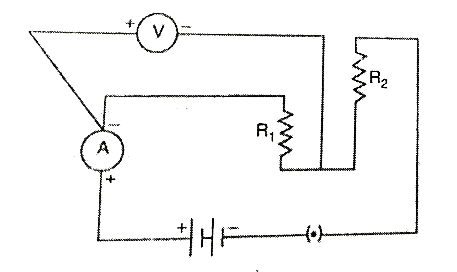
In this circuit, the :
View SolutionA student while performing the experiment to find the resultant resistance of two resistors connected in series observes the ammeter pointer at position P when the key is 'off' and the same pointer at position Q when the key is 'on'.
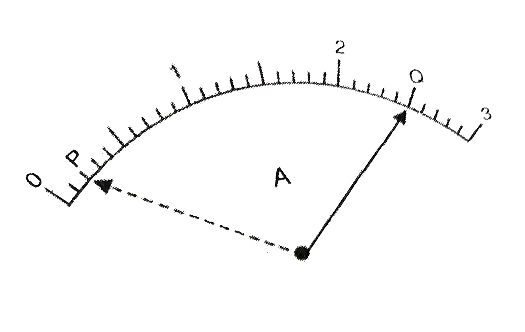
The correct reading of ammeter is :
View SolutionWhile performing an experiment to determine the equivalent resistance of two resistors connected in parallel, a student observes the pointer of voltmeter at position X when the key is 'off' and the same pointer at position Y when the key is 'on'.
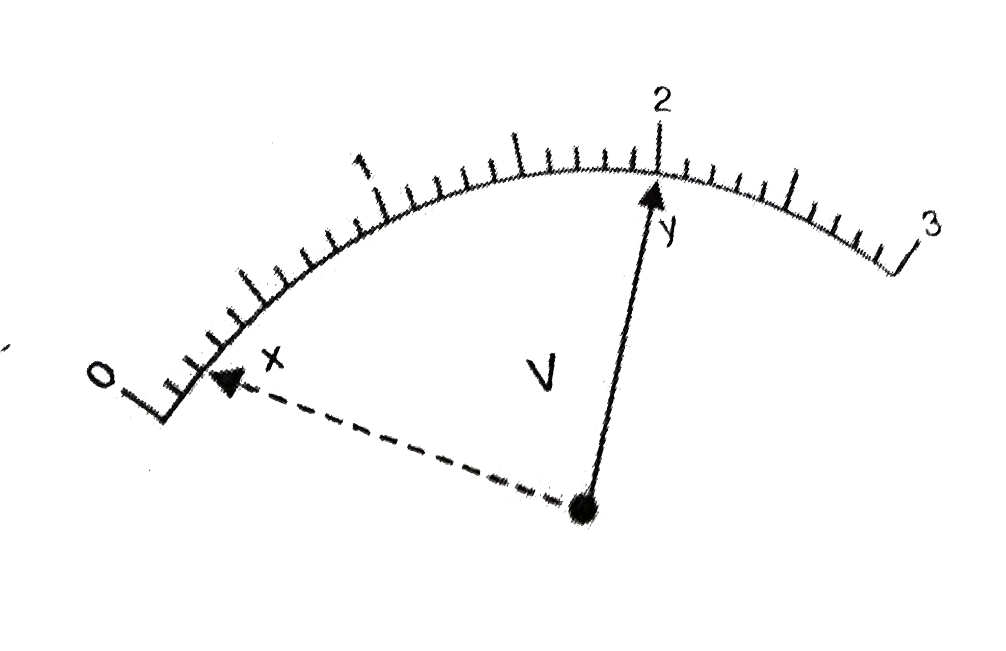
The correct voltmeter reading is :
View SolutionChoose the appropriate set of apparatus for performing the experiment to determine the equivalent resistance of two resistors when connected in series :
View SolutionIn the experiment on finding the equivalent resistance of two resistors connected in series, three students connected the ammeter in their circuits in the three ways X, Y and Z shown here.

Assuming their ammeters to be ideal, the ammeters have been correctly connected in
View SolutionIn the experiment on finding the equivalent resistance of two resistors, connected in parallel, three students connected the voltmeter in their circuits, in the three ways X, Y and Z shown here.
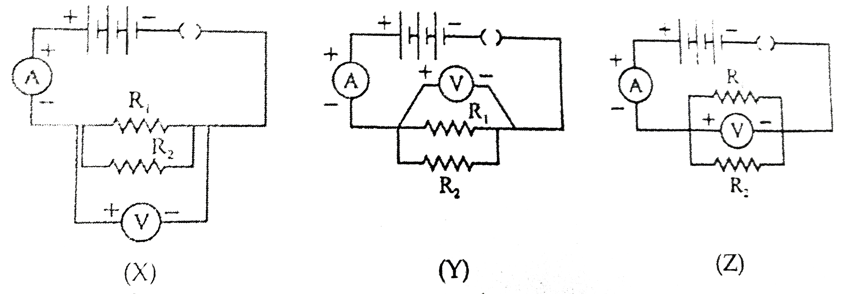
The voltmeter has been correctly connected in
View SolutionThe only correct statement for the following electric circuit is :
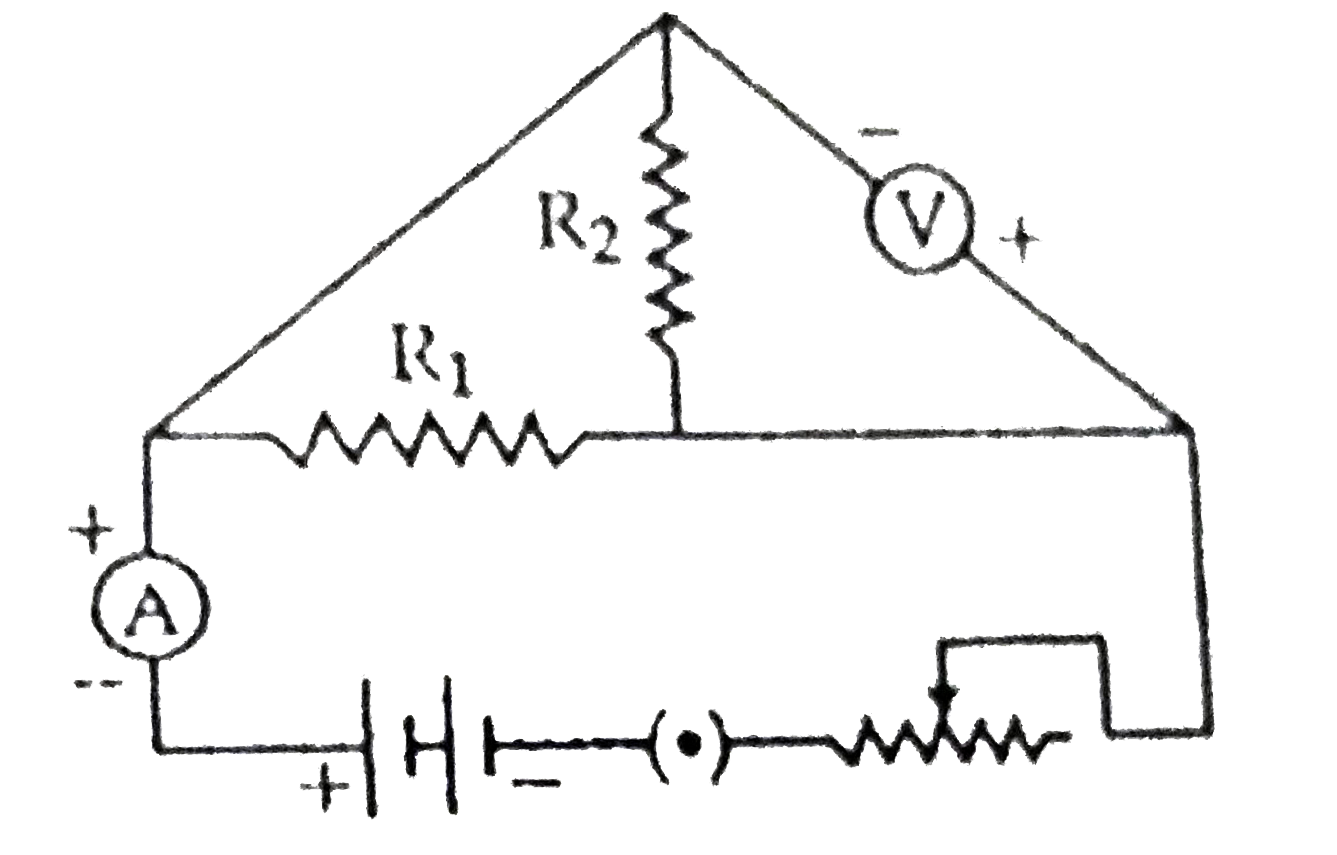
View SolutionThe only correct statement for the two circuits (X) and (Y) shown below is :
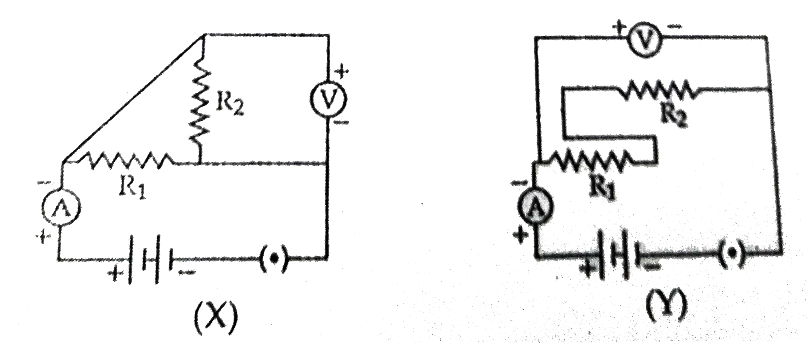
View SolutionFor three circuits, shown here

the same two resistors `R_(1)` and `R_(2)` have been connected in parallel in all the circuits but the voltmeter and the ammeter have been connected in three different positions. The relation between the three voltmeter and ammeter readings would be :
View SolutionTwo students (A) and (B) connect their two given resistors `R_(1)` and `R_(2)` in the menners shown below :

Student (A) connects the terminals marked (`b_(1)`) and `(C_(1))` while student (B) connects the terminals marked `(d_(2))` and `(c_(2))` in their respective circuits at the points marked X and Y.
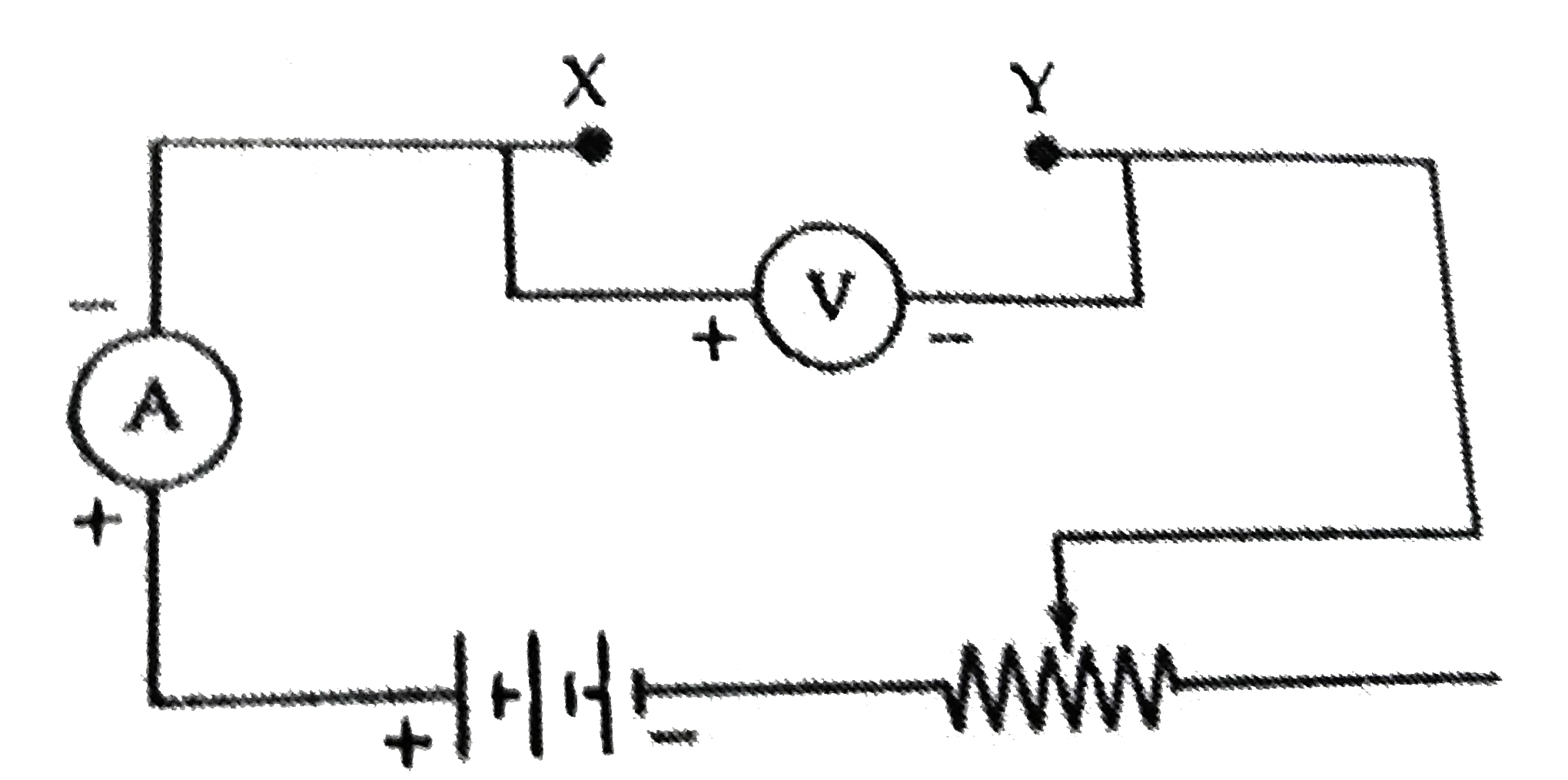
Which one of the following is correct in relation to above arrangements ?
View SolutionThree students (A), (B) and (C) connect their two given resistors `R_(1)` and `R_(2)` in the manners shown below :

They connect the terminals marked X and Y above to the terminals marked X and Y in the circuit given below:
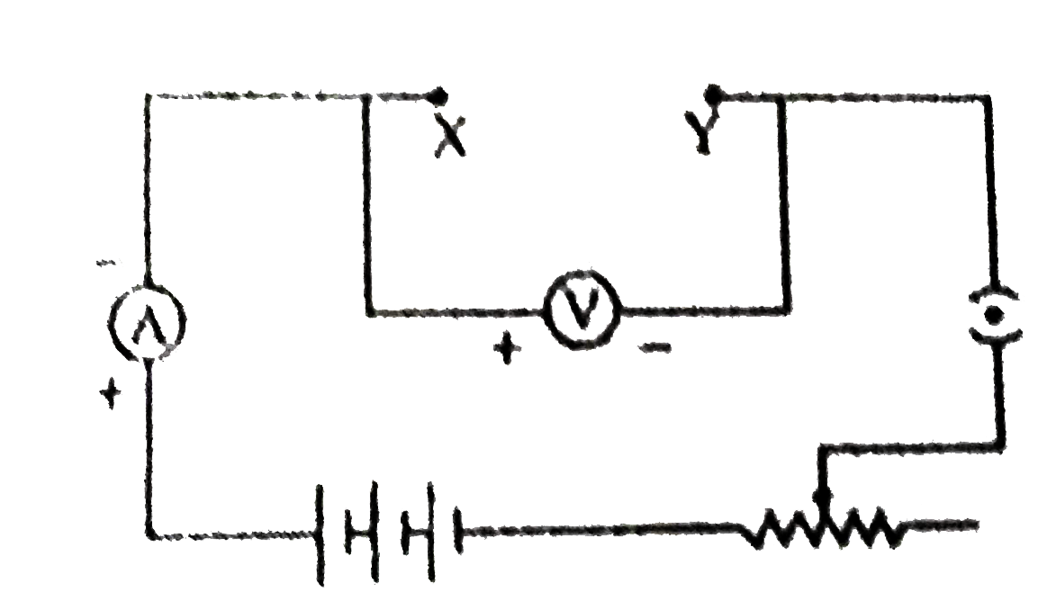
The record the Ammeter readings (I) for different positions of the rheostat and the corresponding Voltmeter readings (V).
The average value of the ratio V/I in their observations would be minimum for :
View SolutionStudents A and B connect the two resistors `R_(1)` and `R_(2)` given to them in the manners shown below :

and then insert them at X and Y into the measuring circuit shown below :
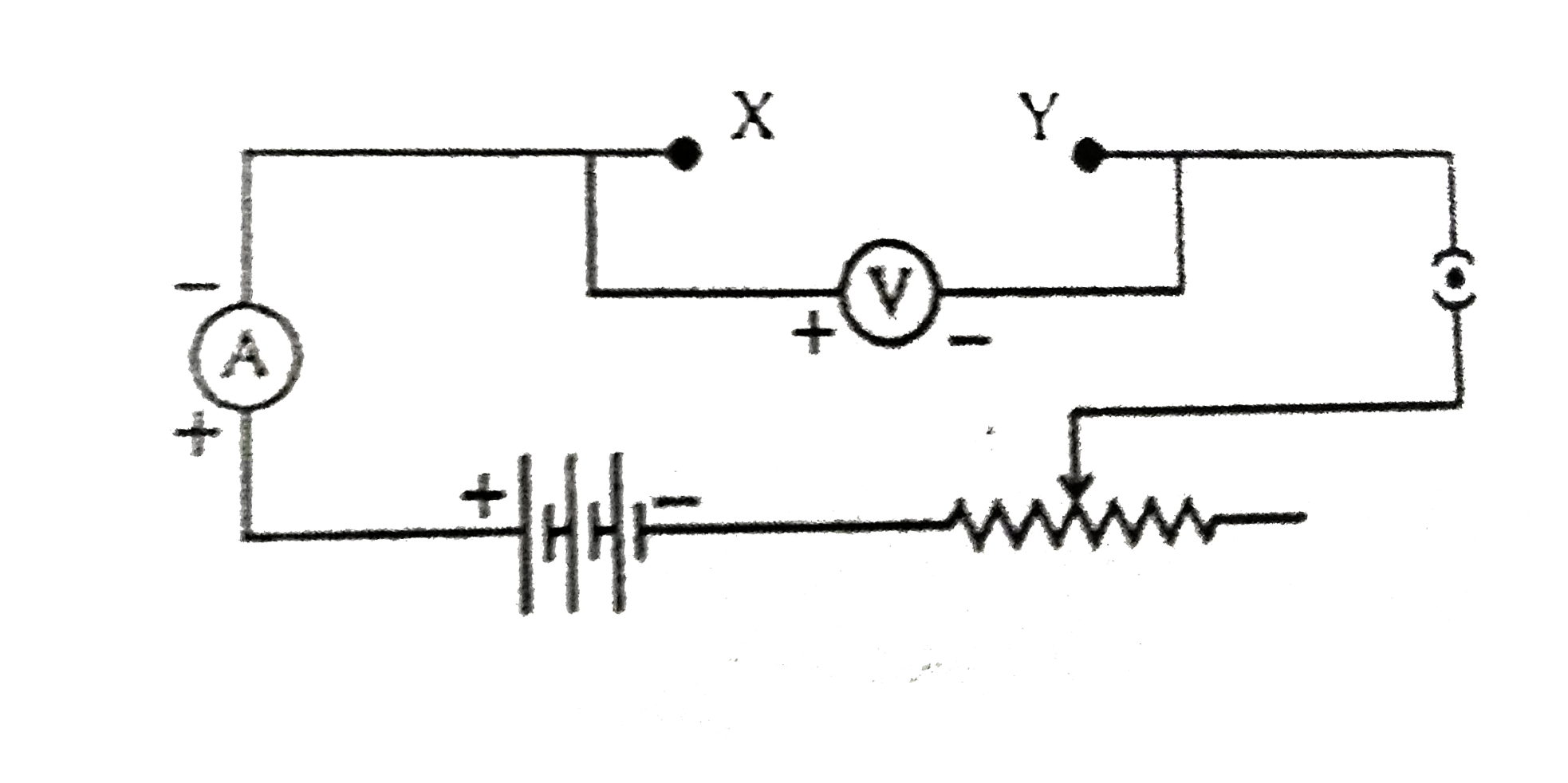
We can then say that
View SolutionA student carries out the experiment for studying the dependence of current (I) flowing through a resistor system of `R_(1)` and `R_(2)` on the potential difference (V) applied to it by connecting the resistor system to points X and Y of the measuring circuit as shown :
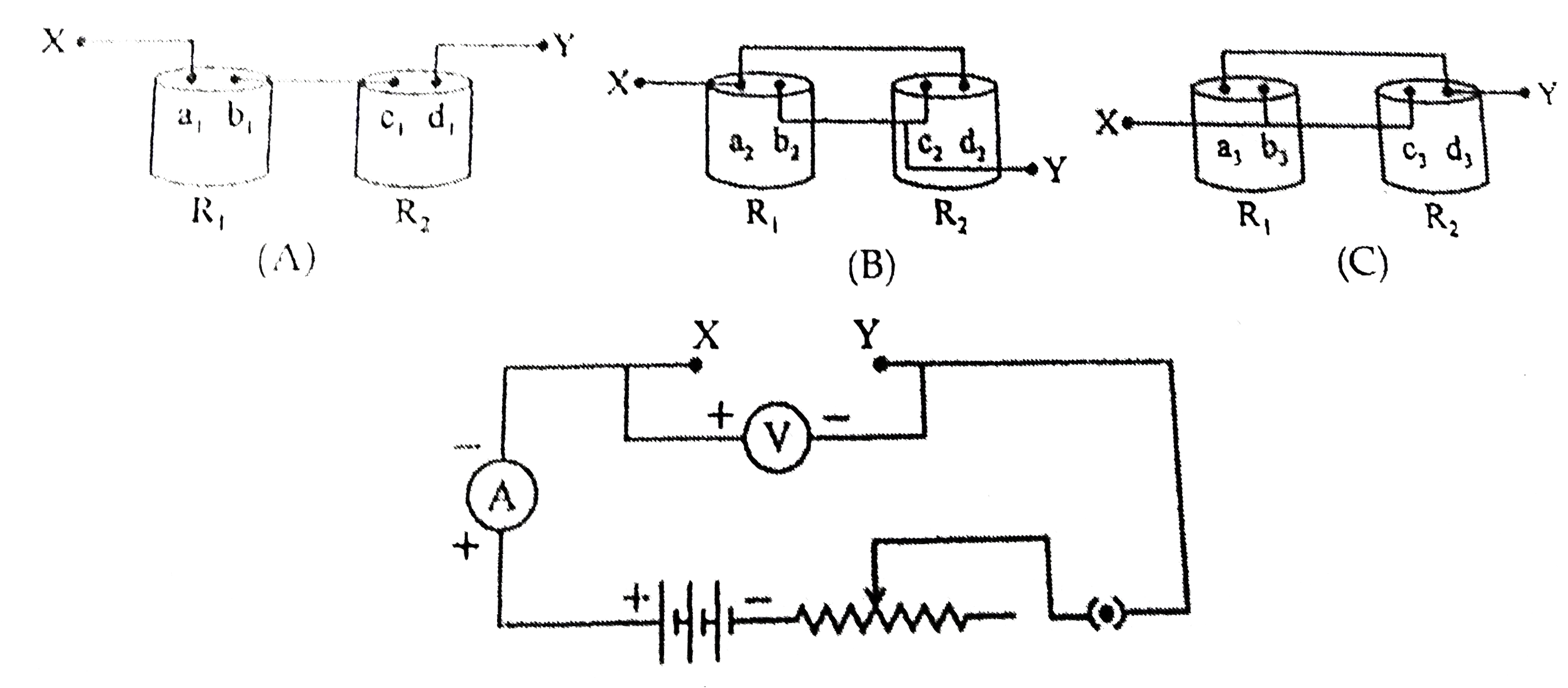
The average value of the ratio V/I, of his observations, would then be equal
View SolutionFor students performed experiments on series and parallel combination of two given resistors `R_(1)`and `R_(2)` which obey Ohm's law and plotted the following V-I graphs :

Which of the graphs is correctly labelled in terms of 'series' and 'parallel' ?
View SolutionYou are given four ammeters A, B, C and D having the least counts mentioned below :
Which of the ammeters would you prefer for doing an experiment to determine the equivalent resistance of two resistance most accurately, when connected in parallel?
View SolutionConsider the two circuits A and B given alongside :
In the circuits A and B shown here, the voltmeter reading would be :
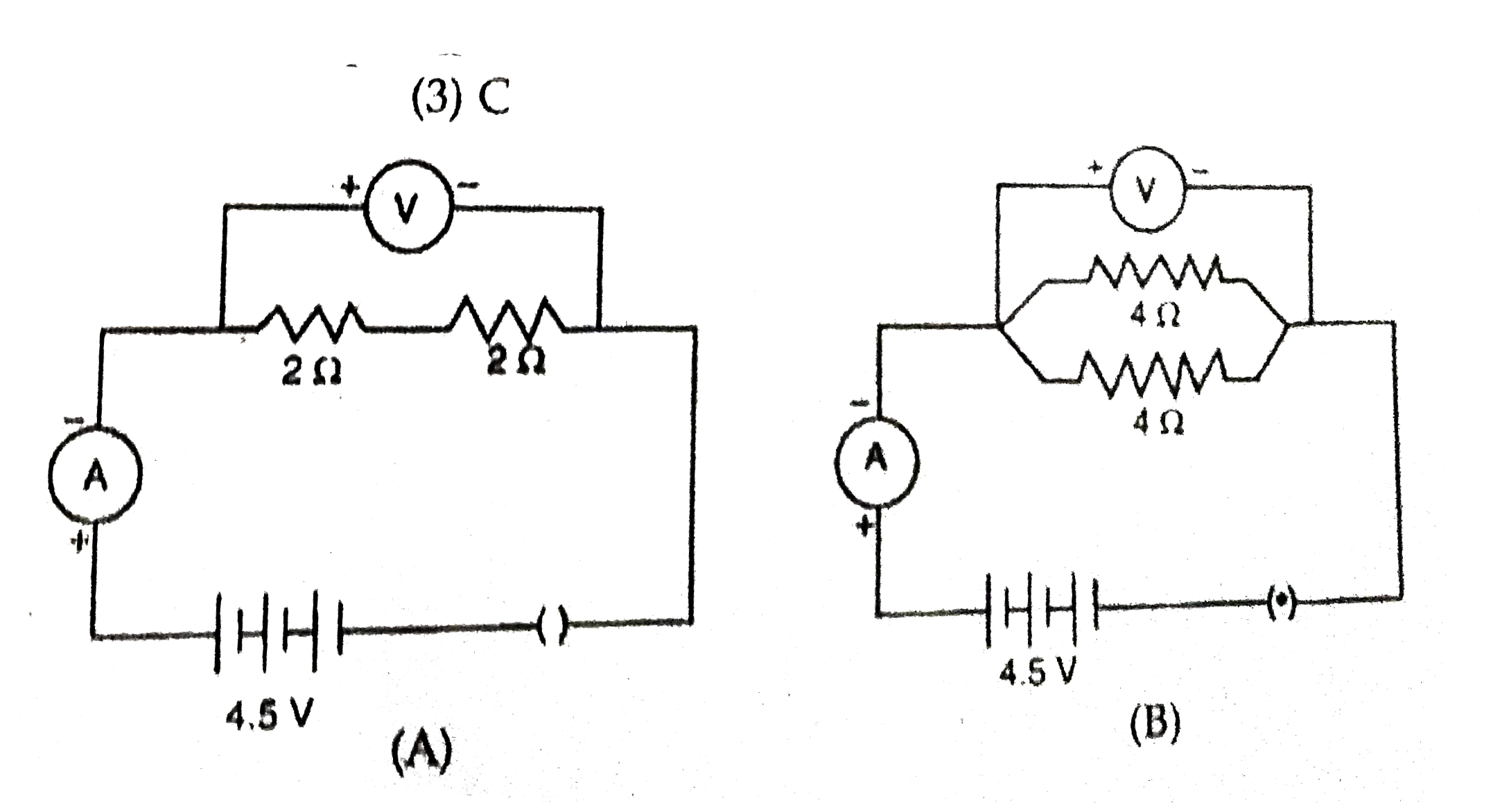
View SolutionThe values of resistance marked on the coils `R_(1)` and `R_(2)` are found to be correct. A student connects the given resistors in the following manner (as shown in Figure 1).

He then connects the terminals marked X and Y of the above combination of resistors `R_(1)` and `R_(2)` to the terminals marked X and Y in the circuit (shown in Figure 2).
The average value of the ratio V/I in the obervations recorded in the circuit would be :
View SolutionA student using the same two resistors, ammeter, voltmeter and battery, sets up two circuits A and B connecting the two resistors first in series and then in parallel.
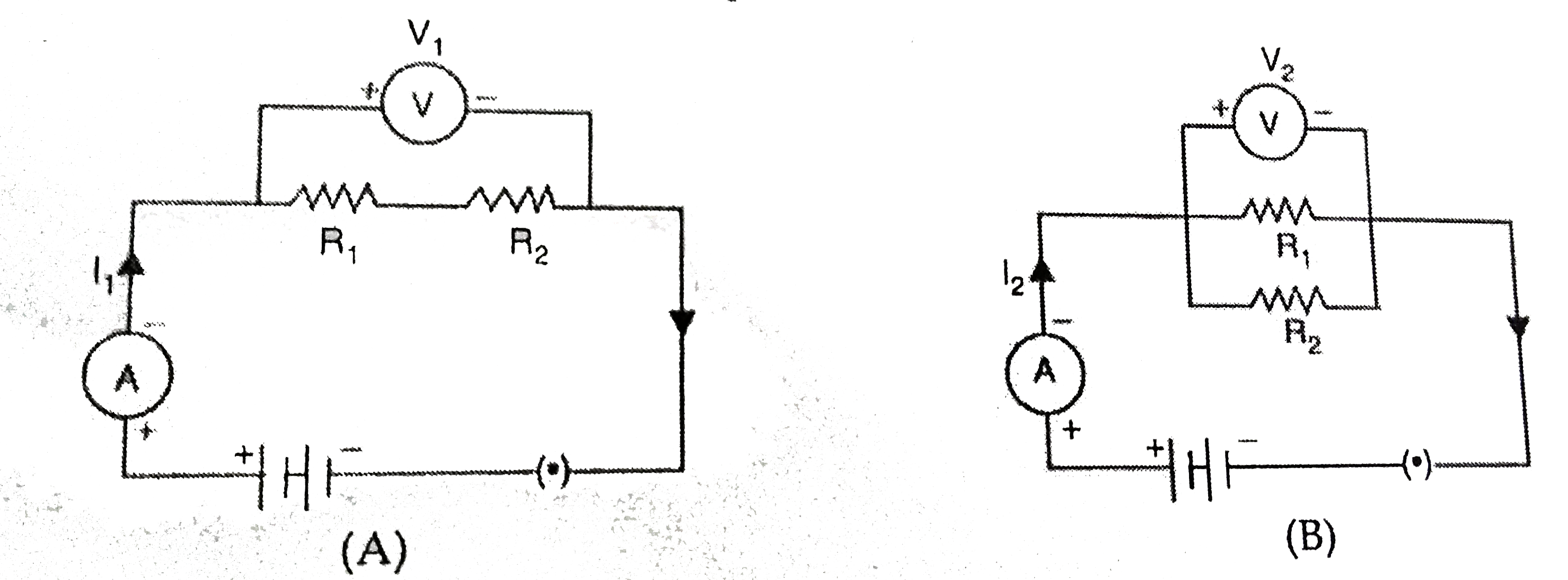
If the ammeter and voltmeter readings in the two cases be `I_(1), I_(2)` and `V_(1), V_(2)` respectively, he is likely to observe that :
View SolutionTwo students made two circuits A and B to determine the resultant resistance of two resistors `R_(1)` and `R_(2)` connected in series :
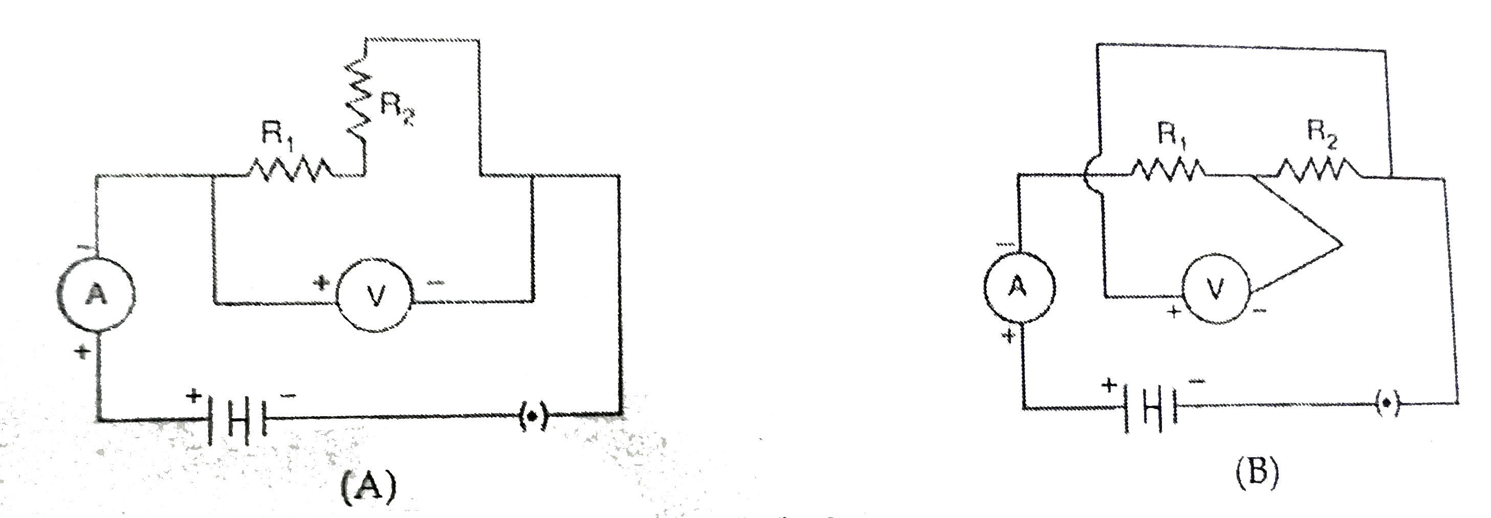
All the components have been connected correctly in :
View SolutionFour student have made the following circuit diagrams for determining the equivalent resistance of two resistors connected in series :
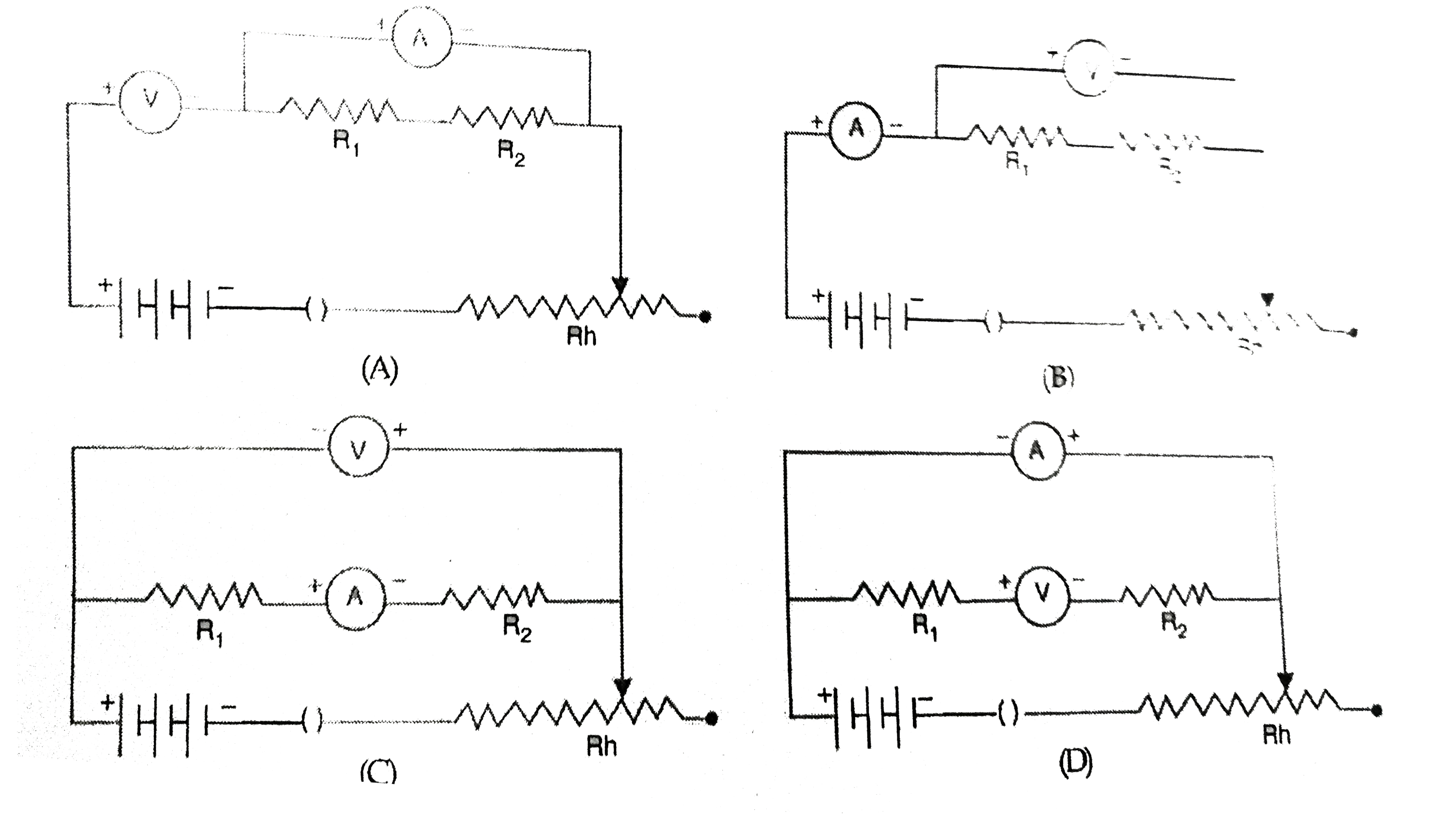
The correct circuit diagram is :
View SolutionConsider the following four circuits P, Q, R and S which have been set up to find the resultant resistance of two resistors combined in parallel :
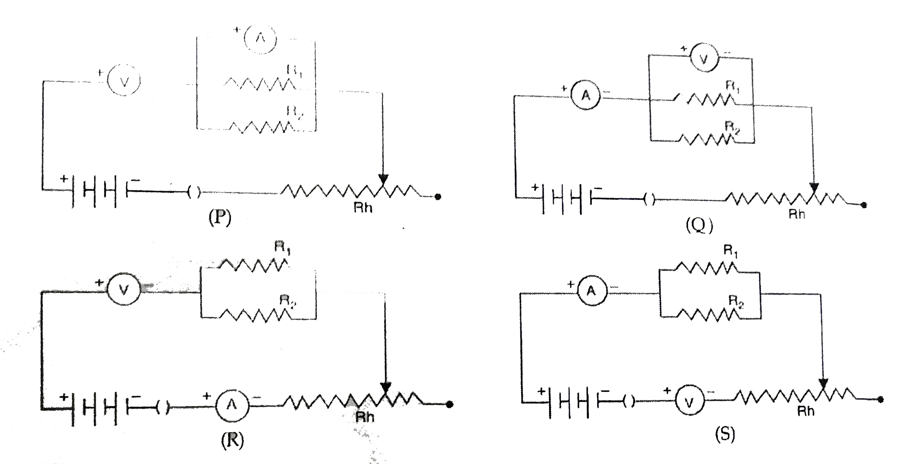
The correct way of connecting the ammeter and voltmeter in the circuit is :
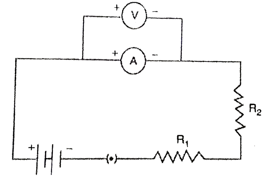
View SolutionIn order to determine the equivalent resistance of two resistors `R_(1)` and `R_(2)` connected in series, a student made this circuit for his experiment.
The only statement which is true for this circuit is that it gives :
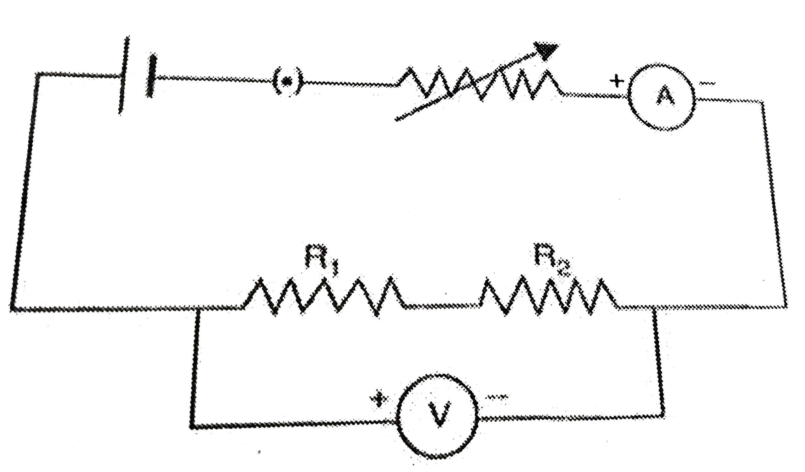
View SolutionTo find the resultant resistance of two resistors when connected in series, a student arranged the various components according to the circuit shown alongside :
The student, however, did not succeed in his objective. Which of the following mistake has been made by the student in setting up the circuit ?
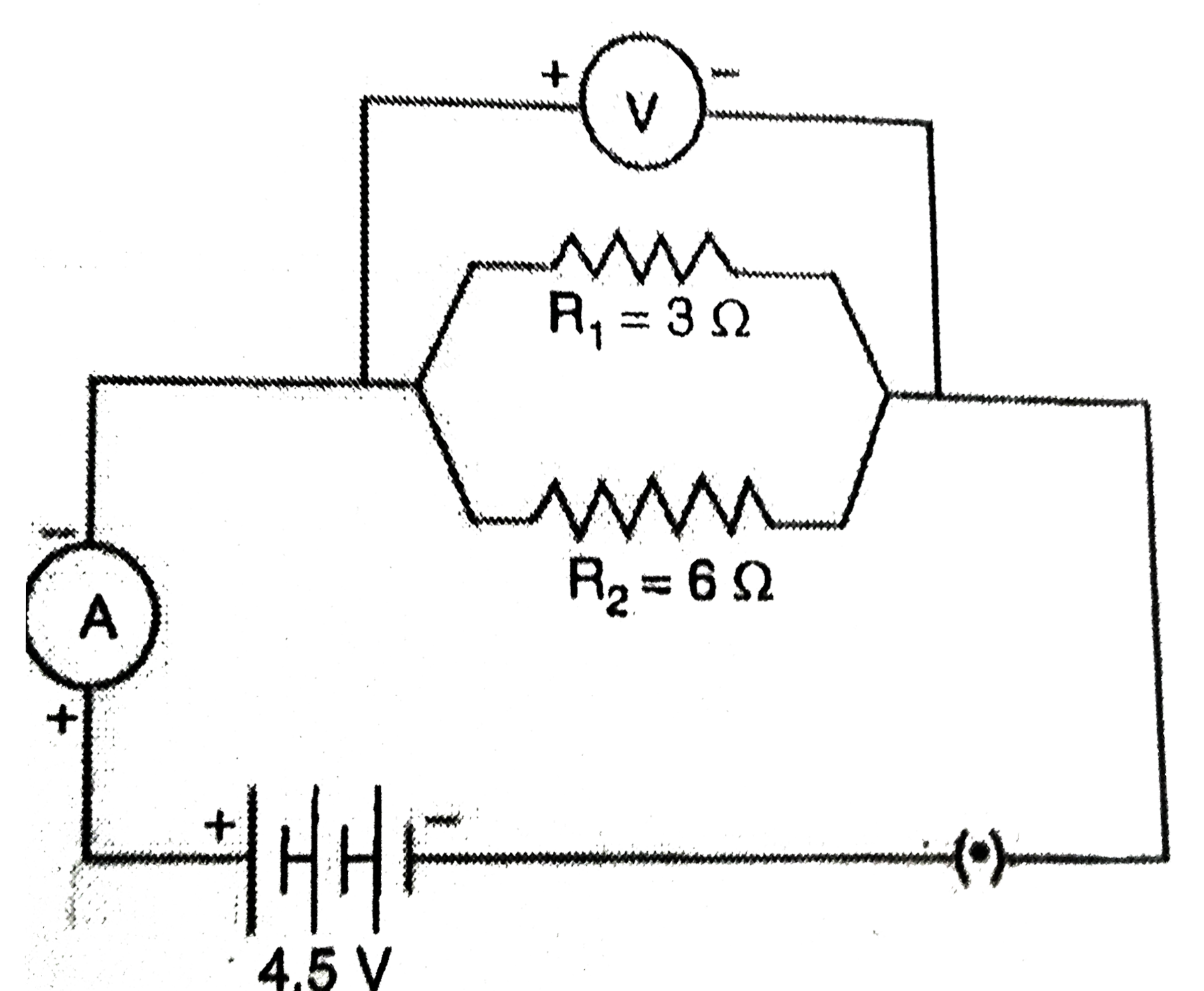
View SolutionThe following apparatus is available in a laboratory :
Battery : adjustable from 0 to `4.5 V`
Resistors : `3 Omega` and `6 Omega`
Ammeters : `A_1` of range 0 to 3 A , least count `0.1 A`
`A_2` of range 0 to 1 A , least count `0.05 A`
Voltmeters : `V_1` of range 0 to 10 V , least count `0.5 V`
`V_2` of range 0 to 5 V , least count `0.1 V`
Which is the best combination of votmeter and ammeter for finding the equivalent resistance of the resistors in series ?
View SolutionThe following pieces of apparatus are available in a laboratory :
Battery : adjustable from 0 to 6 V
Resistors : `3 Omega` and `6 Omega`
Ammeters : `A_1` of range 0 to 5 A , least count `0.25 A`
`A_2` of range 0 to 3 A , least count `0.1 A`
Voltmeters : `V_1` of range 0 to 10 V , least count `0.5 V`
`v_2` of range 0 to 5 V , least count 0.1 V
For the experiment to find the equivalent resistance of the parallel combination of the two given resistors, which is the best choice ?
View SolutionThe ammeter, voltmeter and, resistors `R_(1)` and `R_(2)` connected in the circuit as shown below have been checked and found to be correct.
On plugging the key, the voltmeter reads 4.5 V but the ammeter reads 1.5 A. This is most likely because the wires joined to :
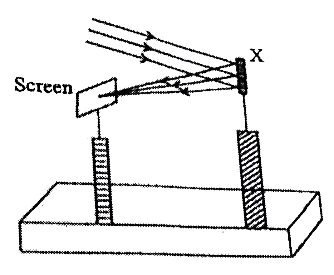
View SolutionA student determines the focal length of a device X, by focusing the image of a far off object on the screen positioned as shown in the figure alongside.
The device X is a :
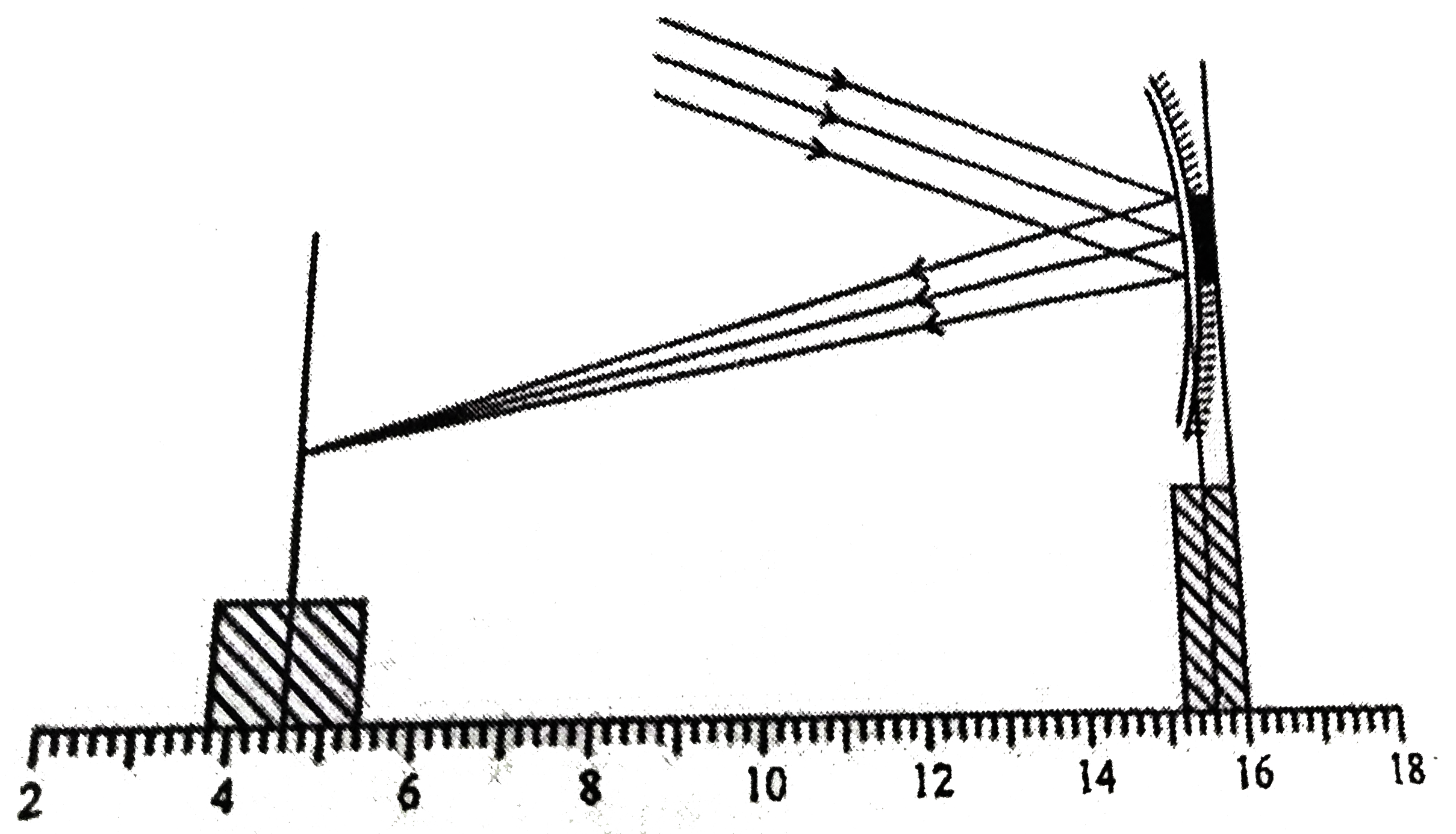
View SolutionThe focal length of the concave mirror in the experimental set up, shown alongside, equals :
View SolutionWhile determining the focal length of a concave mirror, a student obtained the image of a distant object on a screen. In order to get the focal length of the mirror, the student should measure the distance :
View SolutionA student obtains a blurred image of a distant object on a screen using a convex lens. To obtain a distinct image on the screen he should move the lens
View SolutionFour students A, B, C and D performed the experiment to determine the focal length of a concave mirror by obtaining the image of a distant tree on a screen. They measured the distances between the screen and the mirror as shown in the diagrams given below :

The correct value for focal length will be obtained by the student :
View SolutionA student has to do the experiment on finding the focal length of a given concave mirror by using a distant object. Out of the following 'set-ups' A,B,C and D available to him:
A : a screen, a mirror holder and a scale
B : a mirror holder, a screen holder and a scale
C : a screen holder and a scale
D : a mirror holder and a scale
The 'set-up' which is likely to give him the best result is :
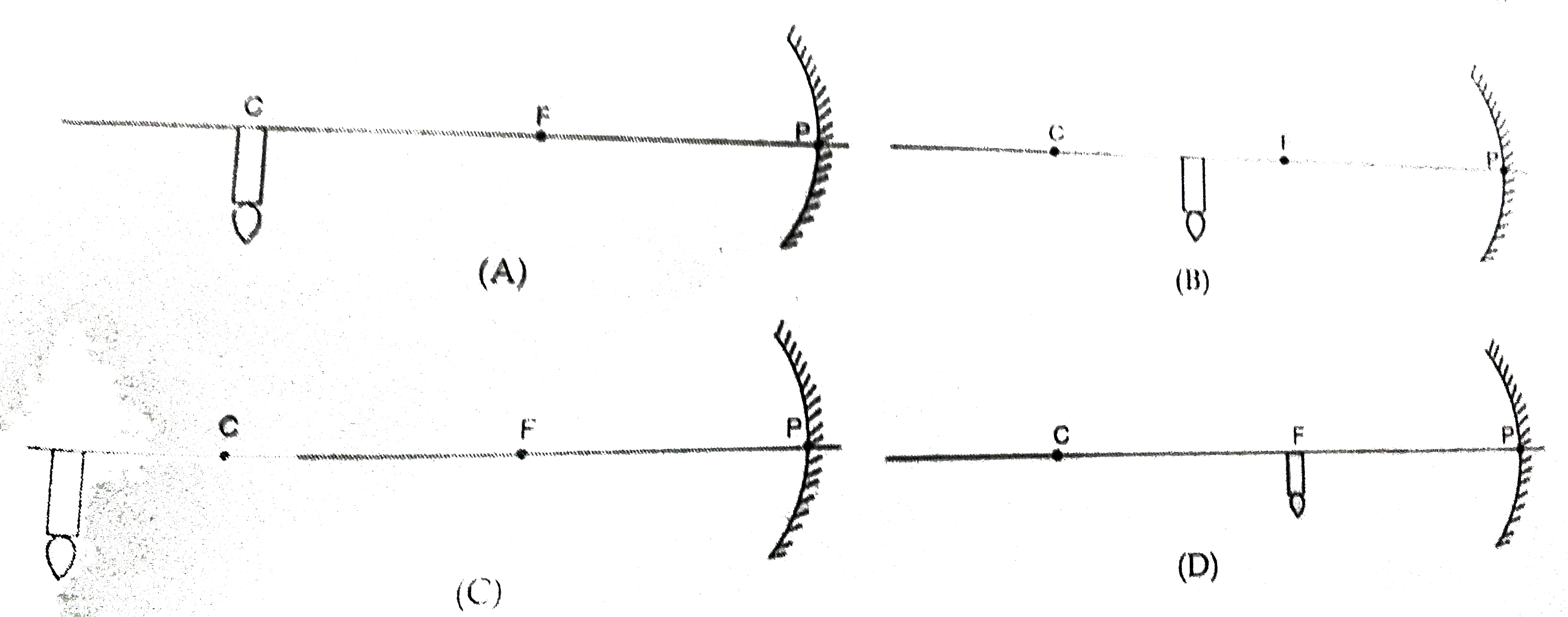
View SolutionFour student A,B,C and D performed an experiment to detemine the focal length of a concave mirror by using a lighted candle kept at a considerable distance as the object. They represented the position of image by drawing the following diagrams :
Which diagram describes the correct position of the image of the candle ?
View SolutionThe parallel rays form the top of a distant tree are incident on a concave mirror forming its image on a screen.
The diagram which shows the image of the tree on the screen correctly is :

View SolutionIn order to determine the focal length of a concave mirror, a student obtained a sharp image of the grill of a window in the laboratory wall on a screen. His teacher suggested that to get better result for focal length, he should focus a distant tree instead of the window grill. In which direction should the mirror be moved for for this purpose so as to get a sharp image of the tree on the screen ?
View SolutionIn order to determine the focal length of a concave mirror, a student obtained the sharp image of a distant tree on a screen. In order to obtain a sharp image of a window grill of the laboratory on the same screen, in which direction should the screen be moved ?
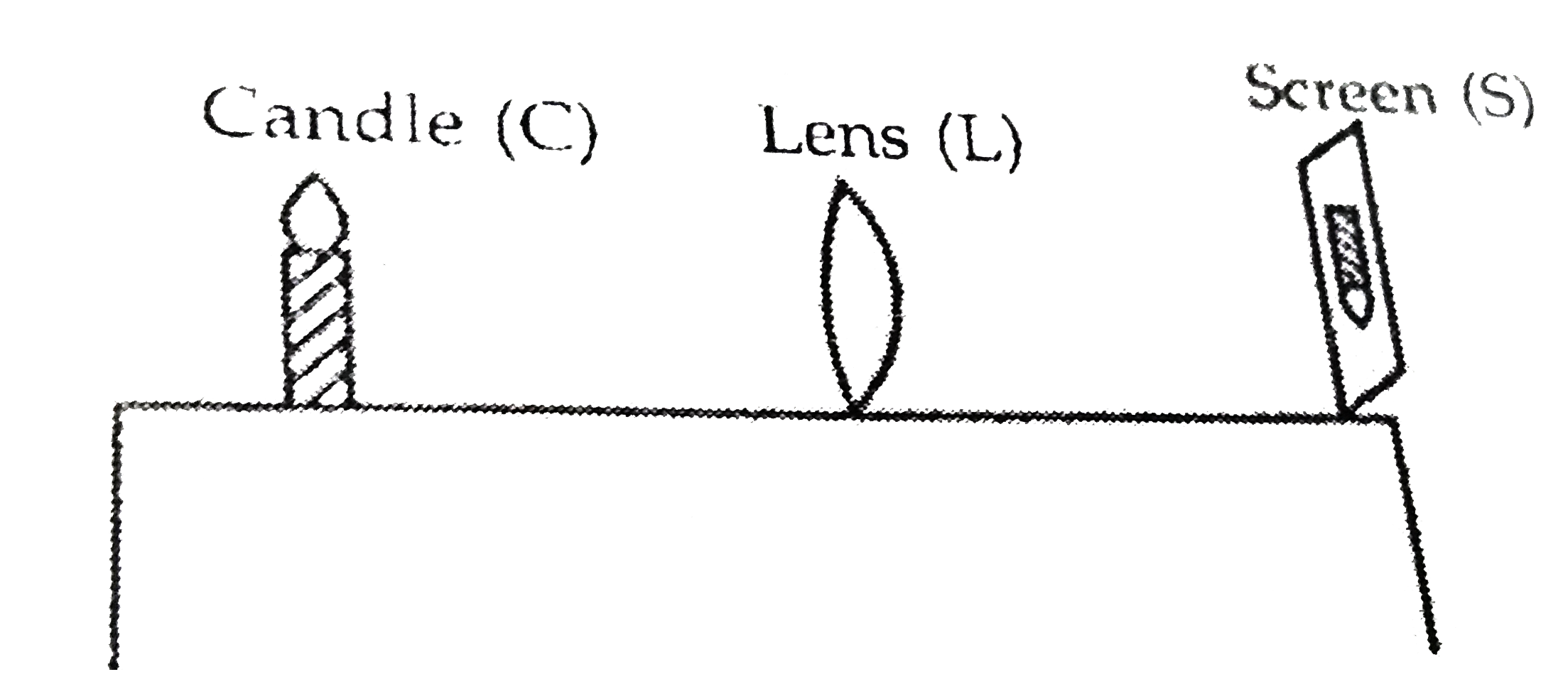
View SolutionA student performs an experiment on finding the focal length of a convex lens by keeping a lighted candle on one end of laboratory table, a screen on its other end and the lens between them as shown in the figure. The positions of the three are adjusted to get a sharp image of the candle flame on the screen.
If now the candle flame were to be replaced by a distant lamp on a far away electric pole, the student would be able to get a sharp image of this distant lamp on the screen by moving :
View SolutionA student obtained a sharp image of the grill of a window in the laboratory on a screen, using a convex lens. For getting better results, her teacher suggested focussing of a distant tree instead of the grill. In which direction should the lens be moved for this purpose to get a sharp image on the screen ?
View SolutionA sharp image of a distant object is obtained on a screen by using a convex lens. In order to determine the focal length of the lens, you need to measure the distance between the :
View SolutionWhile performing the experiment to detemine the focal length of a convex lens by using the sun as the distant object, a student could not find a screen with stand. In the absence of a good screen, which of the following method is the most appropriate and safe to be used by the student ?
View SolutionWhile performing an experiment on determining the focal length of a convex lens, a student obtains a sharp inverted image of the laboratory window grill on the screen and measures the distance between the screen and the lens. She then repeats the experiment and takes a distant tree as the object in the second case. In order to get a sharp image of the tree on the screen, she will now have to move the screen :
View SolutionWhile performing the experiment on the determination of focal length of a convex lens, four students obtained the image of the same distant tree on the screen :
Which diagram shows the formation of image correctly ?

View SolutionA student was given the following suggestions by his classmates for performing the experiment on finding the focal length of a convex lens :
(A) Select any object very far away from the laboratory window
(B) Select a well illuminated object far (but not very far) from the laboratory window
(C) Keep all the lights of the laboratory on
(D) Place the lens between the object and the screen
(E) Place the screen between the object and the lens
(F) Obtain the sharpest image of the object on the screen
He can perform the experiment better by following the suggestions :
View SolutionFor performing an experiment, a student was asked to choose one concave mirror and one convex lens from a lot of mirrors and lenses of different kinds. The correct procedure adopted by her will be :
View SolutionA teacher gives a convex lens and a concave mirror of focal length of about 20 cm each to his student and asks him to find their focal lengths by obtaining the image of a distant object.The student uses a distant tree as the object and obtains its sharp image, one by one, on a screen. The distances `d_(1)` and `d_(2)` between the lens/mirror and the screen in the two cases and the nature of their respective sharp images are likely to be :
View SolutionThree students measured the focal length of a convex lens using parallel rays from a distant object. All of the measured the distance between the lens and the inverted image on the screen.
(i) Student A saw a sharp image on the screen and labelled the distance as `f_(1)`
(ii) Student B saw a slightly larger blurred image on the screen and labelled the distance as `f_(2)`
(iii) Student C saw slightly smaller blurred image on the screen and labelled the distance as `f_(3)`
The relation between the three measurements would most likely be :
View SolutionA student has to do the experiment on finding the focal length of a given convex lens by using a distant object. She can do her experiment if she is also made available :
View SolutionA student performs an experiment to estimate the focal length of a convex lens by obtaining the image of a distant window on a white screen. The image formed on the white screen is :
View SolutionFour students A, B, C and D performed an experiment to determine the focal length of a convex lens by using a lighted candle kept at a considerable distance as the object. They represented the position fo image by drawing the following diagrams :
Which diagram describes the correct position of image of the candle ?
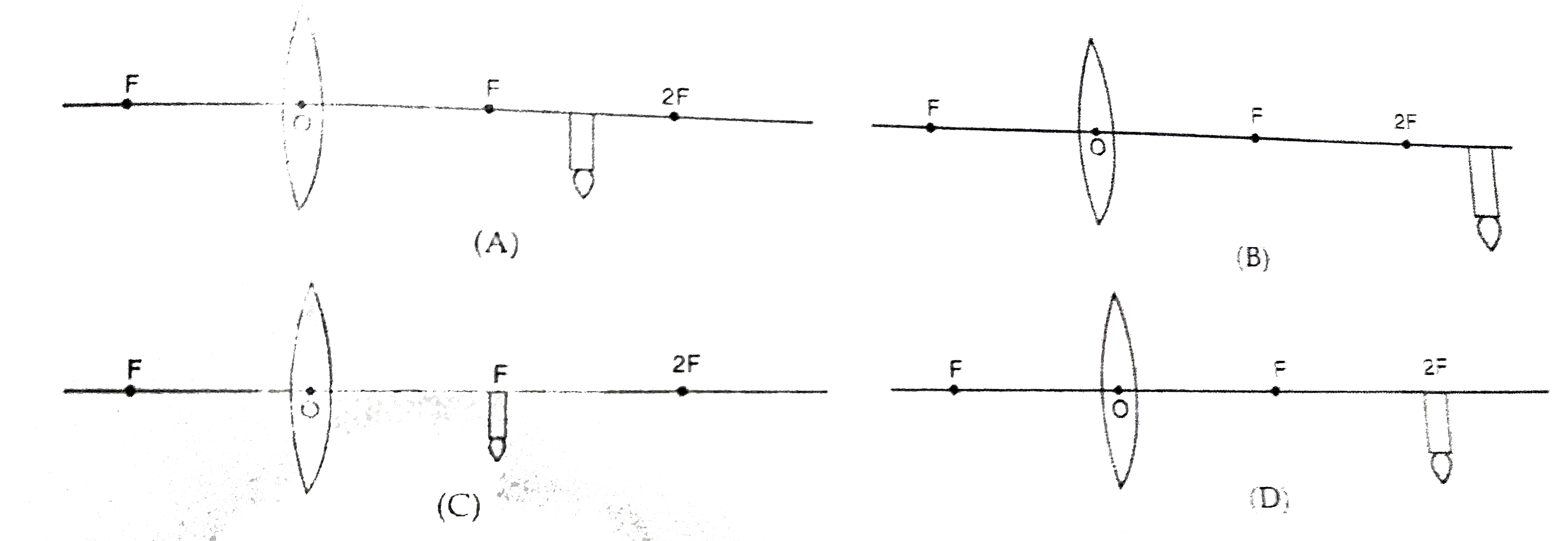
View SolutionA student performs the experiment on tracing the path of a ray of light passing through a rectangular glass slab for different angles of incidence. He measures the angle of incidence `anglei`, angle of refraction `angler` and angle of emergence `angle e` for all his observations. He would find that in all cases :
View SolutionA student does the experiment on tracing the path of a ray of light passing through a rectangular glass slab for different angles of incidence. He can get a correct measure of the angle of incidence and the angle of emergence by following the labelling indicated in figure :

View SolutionA student suggested the following 'guidelines' to his friend for doing the experiment on tracing the path of a ray of light passing through a rectangular glass slab for three different angles of incidence :
A. Draw the 'outline' of the glass slab at three positions on the drawing sheet.
B. Draw 'normals' on the top side of these 'outlines' very near their left end.
C. Draw the incident rays on the three 'outlines' in directions making angles of `30^(@), 45^(@), 60^(@)` with the normals drawn.
D. Fix two pins vertically on each of these incident rays at two points nearly 1 cm apart.
E. Look for the images of the 'heads' of these pins while fixing two pins from the other side, to get the refracted rays.
When he showed these 'guidelines' to his teacher, the teacher corrected and modified the 'guidelines' labelled as
View SolutionA student traces the path of a ray of light passing through a rectangular glass. Slab.

For measuring the angle of incidence, he must position the protractor in the manner shown in figure :
View SolutionA student performed the experiment of glass slab and with different angles of incidence measured the angles of refraction and emergence in each case. He then recorded his observations as given in the table.
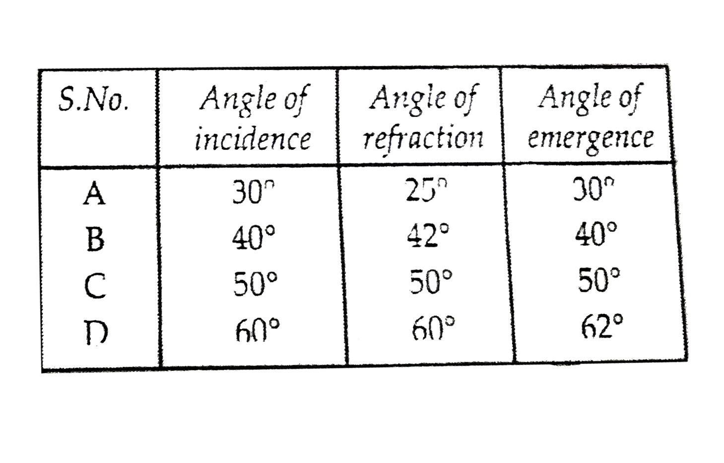
The correct observation is :
View SolutionFour students A, B, C and D showed the following traces of the path of a ray of light passing through a rectangular glass slab.
The trace most likely to be correct is that of student :

View SolutionIn an experiment on tracing the path of a ray of light through a rectangular glass slab, four students A, B, C and D used the following values of the angle of incidence and the distance between the feet of the two pins (fixed on the incident rays) :
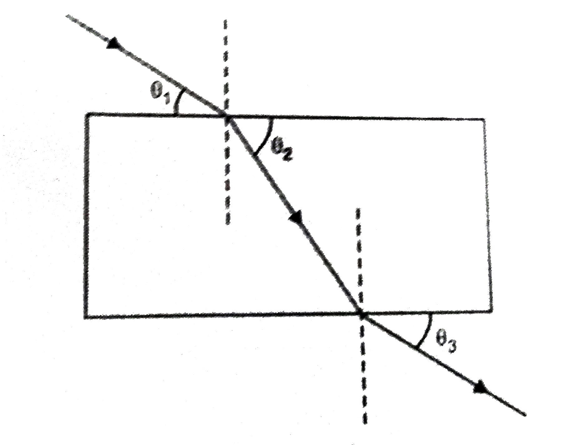
View SolutionA student while doing the experiment on tracing the path of a ray of light passing through a rectangular glass slab measured the three angles marked as `theta_(1), theta_(2) " and " theta_(3)` in the figure.
His measurements could be correct if he were to find :
View SolutionIn the experiment on tracing the path of a ray of light passing through a rectangular glass slab, the correct setting of the protractor (D), for measuring the angle of incidence (`angle I`), and the angle of emergence (`angle e`) correspond, respectively, to diagrams :

View SolutionFour students A, B, C and D selected the following items from the materials available in the science laboratory to perform an experiment to study the refraction of light through a glass slab :
`(A) convex lens, glass slab, pins, drawing board, white paper, scale
(B) glass slab, pins, drawing board, scale, white paper, protractor
(C) glass slab, glass prism, candle, screen, pins, scale, drawing board, protractor
(D) concave mirror, pins, glass slab, protractor, white paper, drawing board
Correct choice of the items required is made by the student :
View SolutionIn an experiment to trace the path of a ray of light passing through a rectangular glass slab, four students measured the angles of incidence (i), angles of refraction (r) and angles of emergence (e) as shown in the diagrams :

The correct measurement is given in the diagram :
View SolutionA teacher asked four students to record the observations of the experiment on tracing the path of a ray of light through a rectangular glass slab. The students recorded their observations under the following headings :
(1) Angle of incidence, Angle of refraction, Angle of reflection
(2) Angle of incidence, Angle of deviation, Angle of emergence
(3) Angle of incidence, Angle of reflection, Angle of emergence
(4) Angle of incidence, Angle of refraction, Angle of emergence
The correct observations were recorded by the student :
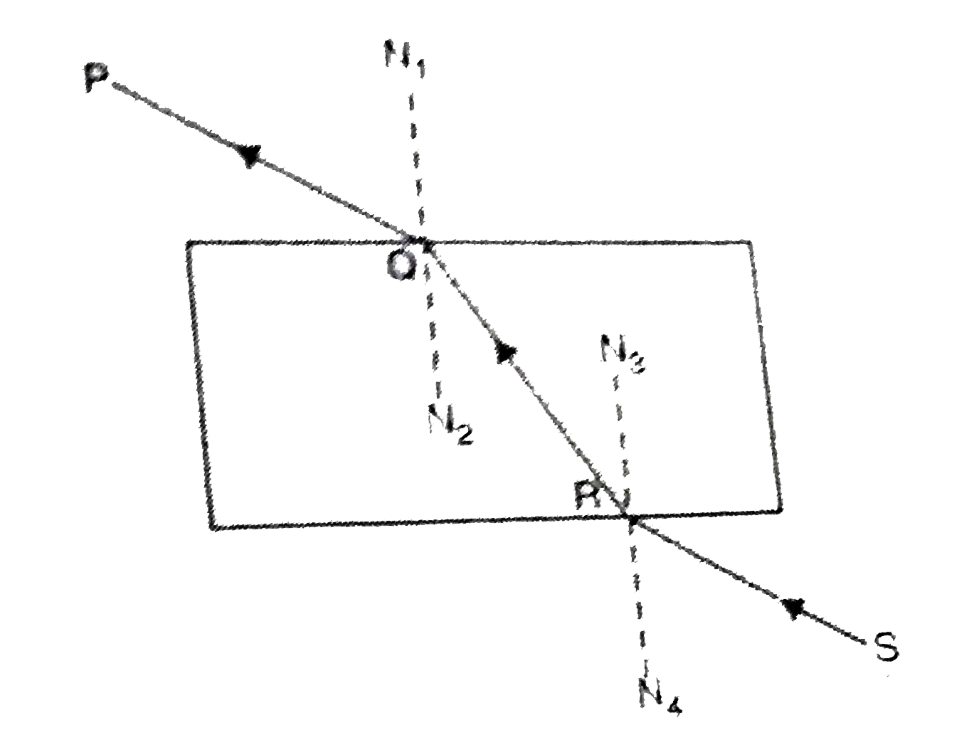
View SolutionAn experiment for tracing the path of a ray of light through a glass slab was set up in the laboratory and ray diagram was drawn as shown here.
The teacher asked the students to identify the refracted ray. The correct answer is :
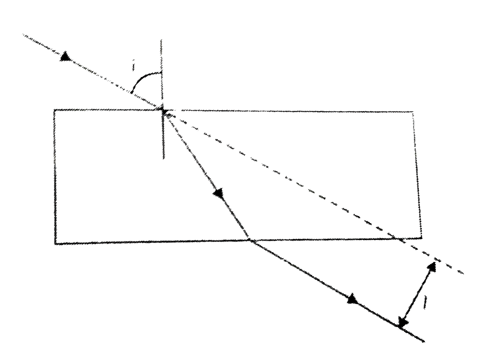
View SolutionA student traces the path of a ray of light passing through a rectangular glass slab for three different values of angle of incidence `(angle i)` namely `30^(@), 45^(@)` and `60^(@)`. He extends the direction of incident ray by a dotted line and measures the perpendicular distance 'l' between the extended incident ray and the emergent ray. He will observe that :
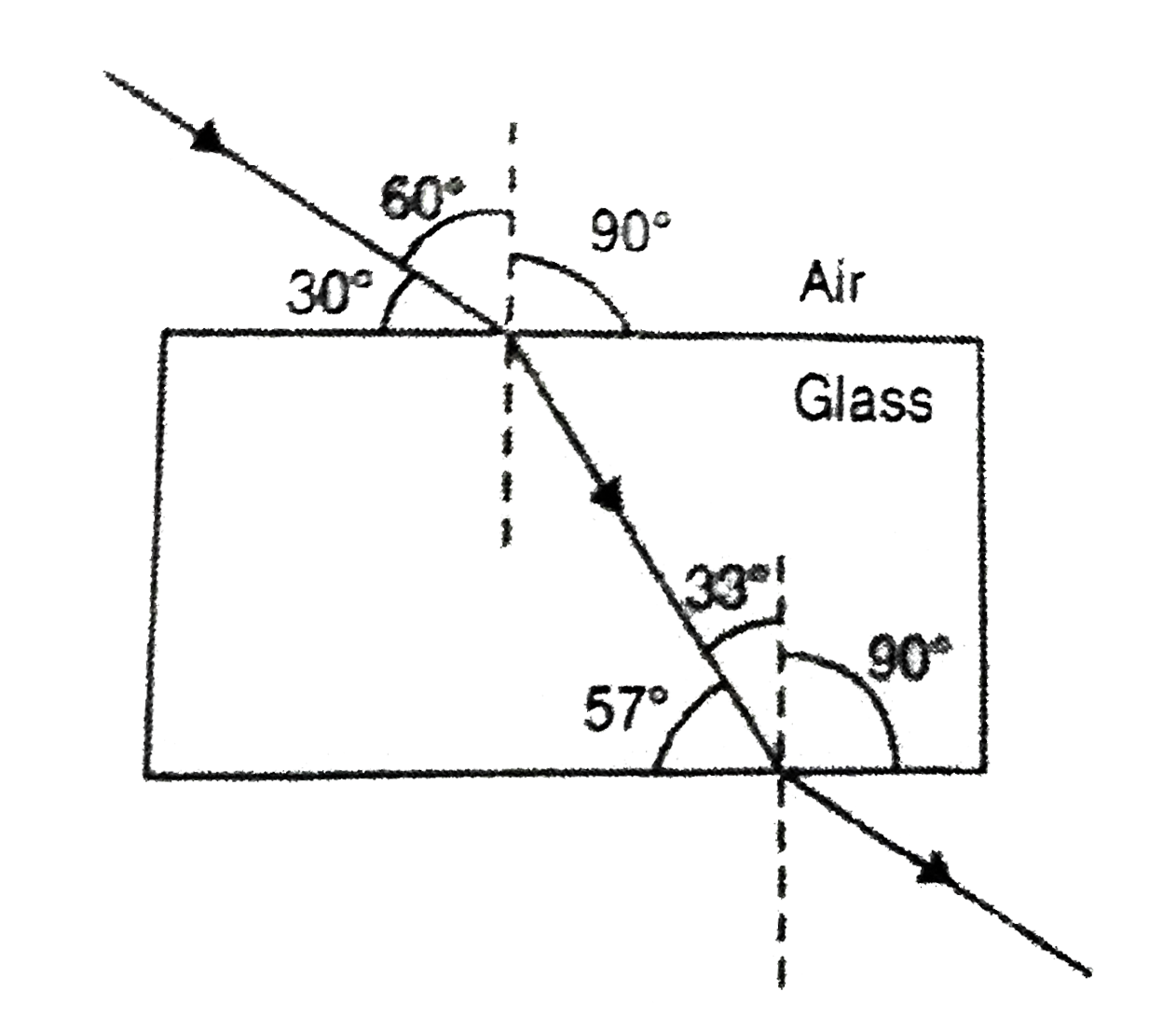
View SolutionA ray of light is incident on a parallel-sided glass slab as shown in the figure. The angle of refraction for this ray of light is likely to be :
View Solution
Multiple Choice Questions questions and complete solutions for chapter THE HUMAN EYE AND THE COLOURFUL WORLD of S CHAND PHYSICS (HINGLISH) of Class 10