Complete Solutions to Exercise 5.2 of chapter ELECTRIC CURRENT AND CIRCUIT of Class 12 book with complete answers and questions
| Class 12 | PHYSICS |
| Chapter | ELECTRIC CURRENT AND CIRCUIT |
| CENGAGE PHYSICS | Exercise 5.2 |
| Number Of Questions | 50 |
| Academic Year | 2023-24 |
Calculate the value of the electic currents `I_1, I_2 and I_3` in the given electrical network.
a. `I_1 = ………..`
b. `I_2 = …………`
c. `I_3 = ……………`
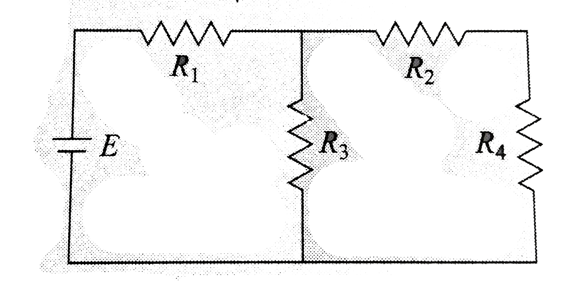
View SolutionDetermine the voltage drop across the resistor `R_1` in the circuit given below with `E = 65V, R_1 = 50Omega, R_2 = 100 Omega, R_3 = 100 Omega` and `R_4 300 Omega`

View SolutionA 20 V battery of internal resistance `1 Omega` is connected to three coils of `12Omega, 6 Omega, and 4Omega` in parallel, a resistor of `5 Omega` and a reversed battery (emf 8 V and internal resistance 2 Omega) as shown in fig Calculate
a. the current in the circuit,
b. current in resistor of `12 Omega` coil, and
c. potential difference across each battery.
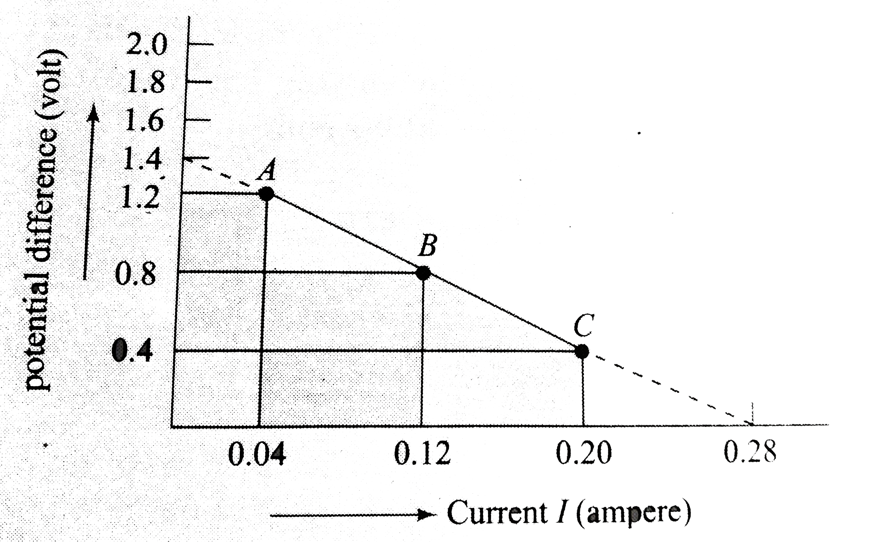
View SolutionPotential difference across the terminals of a cell was measured (in volts) against different current (in ampere) flowing through the cell. A graph was drawn, which was a straight line ABC. Using the data given in the graph determine a. the emf, and
b. the internal resistance of the cell.
View SolutionFind the current in each resistor in the circuit as shown in fig.
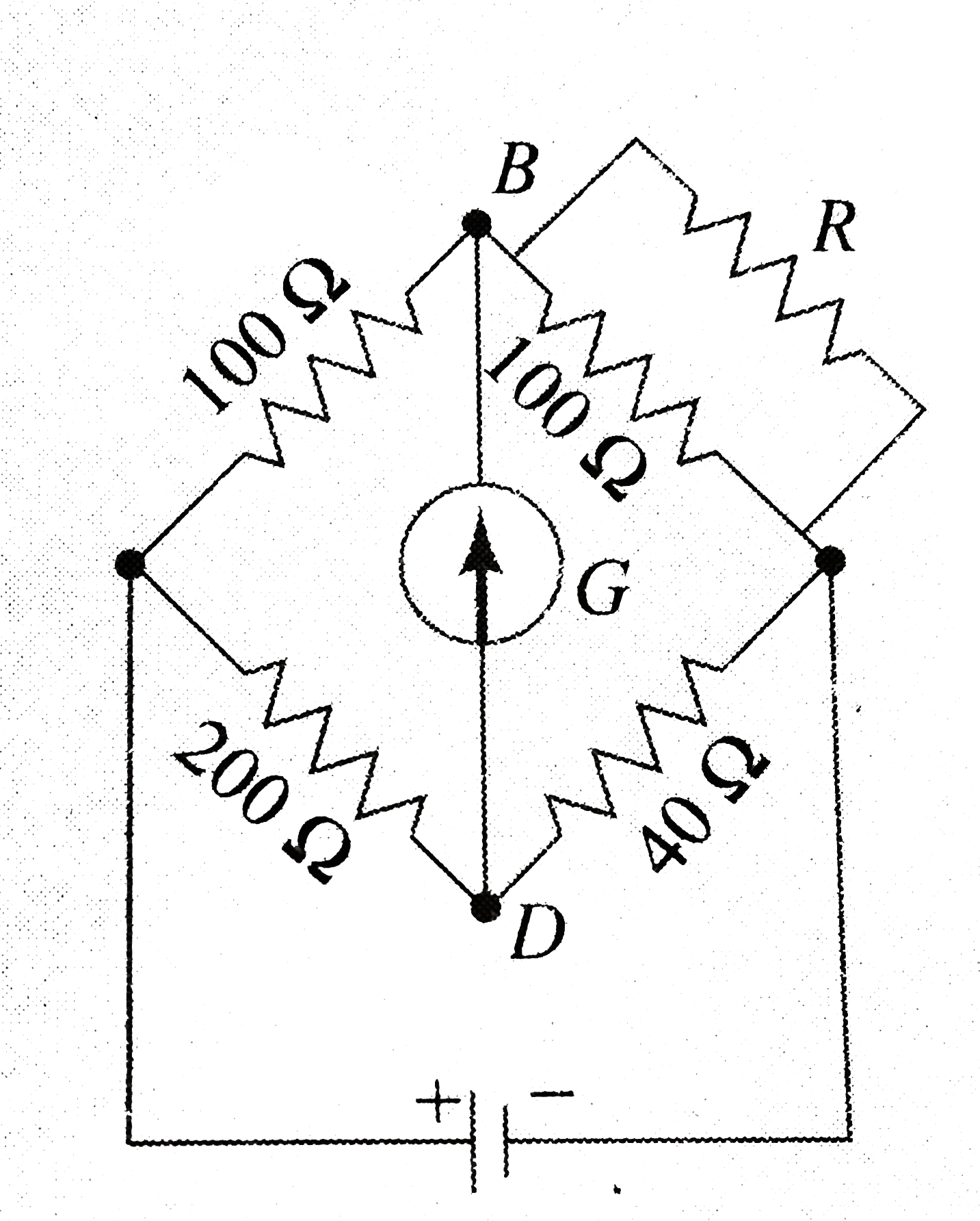
View SolutionThe given Wheatstone bridge is showing no deflection in the galvanometer joined between the points B and D in fig
 Find the value of R
View SolutionWhen 10 identical cells in sereis are connected to the ends of a resistance of `59Omega`, the current is found to be 0.25A. But when the nsame cells, being connected in parallel, are joined to the ends of a resistance of 0.05Omega, the current is 25A. Calculate the internal resistance and the emf of each cell.

View SolutionFind the minimum number of cells required to produce an electric current of `1.5` A through a resistance of `30 Omega`. Given that the emf of each cell is `1.5` V and internal resistance `1.0Omega`.
View SolutionThe current in a simple series cirucit is 5A. When an additional resistance of `2Omega` is introduced, the current is reduced to 4A. Calculate the resistance of the original circuit. Assume that the applied potential difference is the same in both the cases.
View SolutionCalculate the resistance between the terminals A and B of the network shown in fig

View SolutionIn the ciruit the cells `E_1 and E_2` have emfs of 4V and 8V and internal resistance `0.5 Omega and 1.0 Omega,` respectively. Calculate the current through `6 Omega` resistance.

View SolutionDetermine the currents `I_1, I_2, and I_3` for the network shown below
a. `I_1 = ………., b. I_2 = …………. , c. I_3 = …………….`
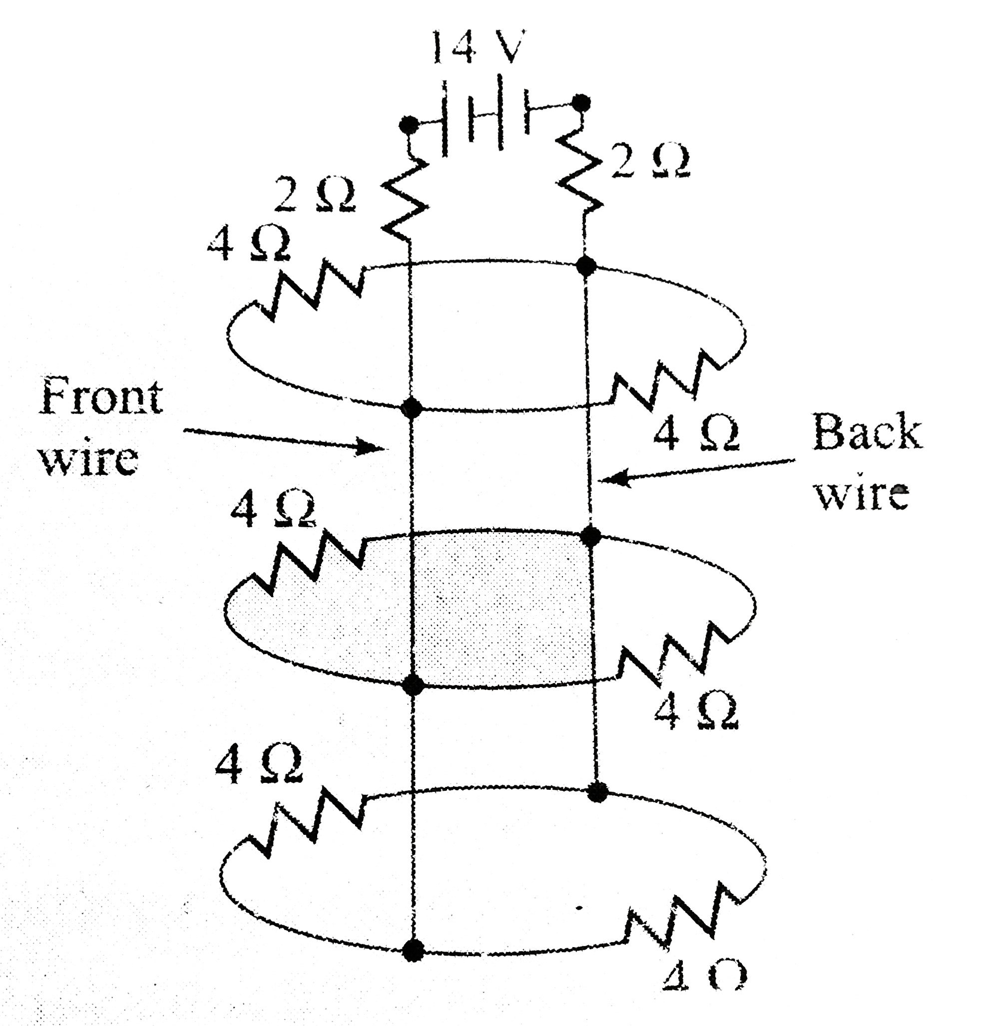
View SolutionFind the current supplied by the source in fig the resistors are mounted around in a cylindrical form.
View SolutionA parallel combination of an `8 Omega` resistor and an unknown resistor R is connected in series with a `16 Omega` resistor and a battery. This circuit is then disassembled, and the three resistors are then connected in series with each other oand the same battery. in both arrangements, the current through the `8 Omega` resistor is the same. What is the unknown resistance R?
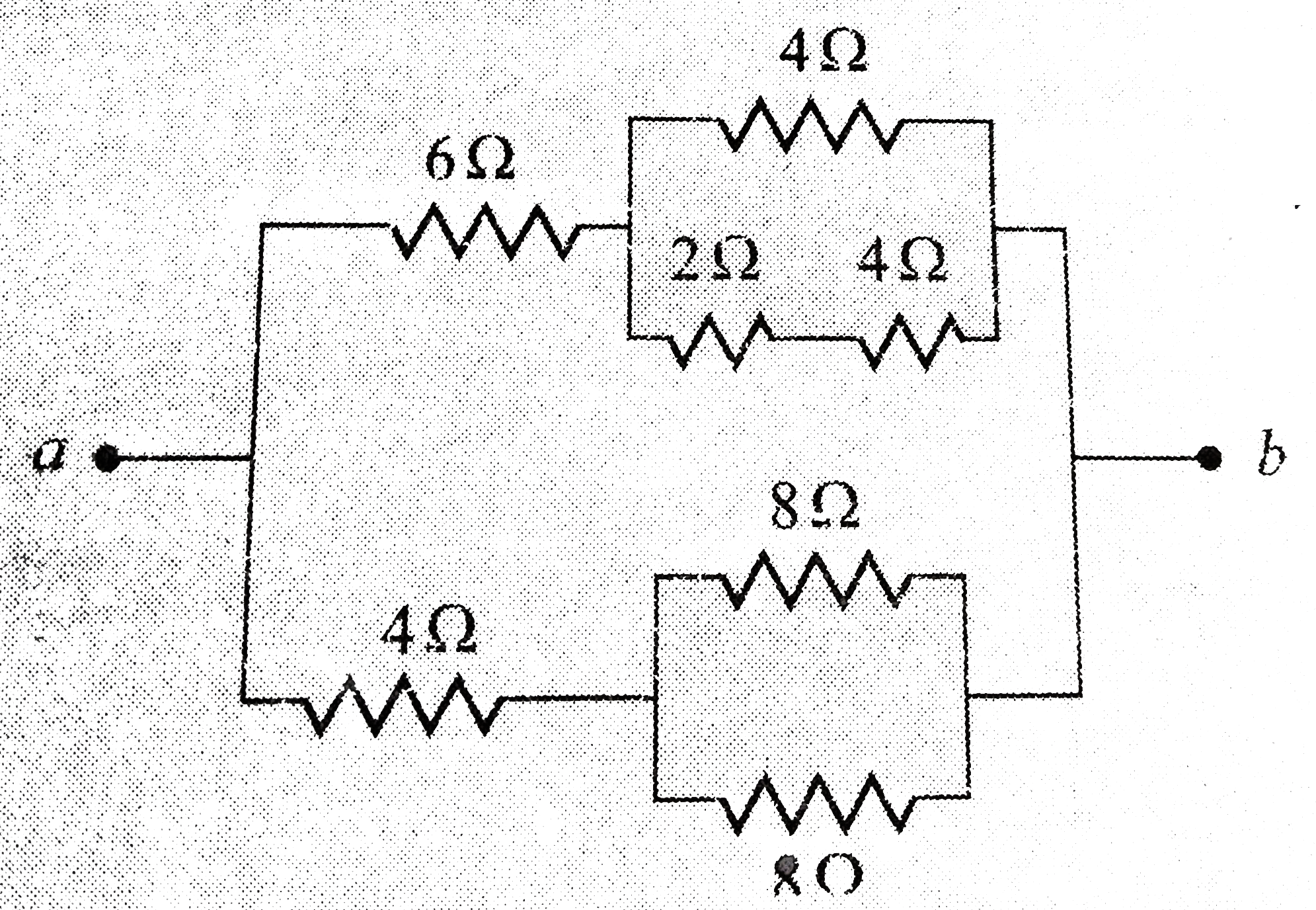
View SolutionFor the resistor network shown in the potential drop between a and b s 12V.
a. Current through resistance of `6Omega is ………..`
b. Current through resistance `2 Omega is ………..`
c. Current through resistance of 8 Omega is ...........`
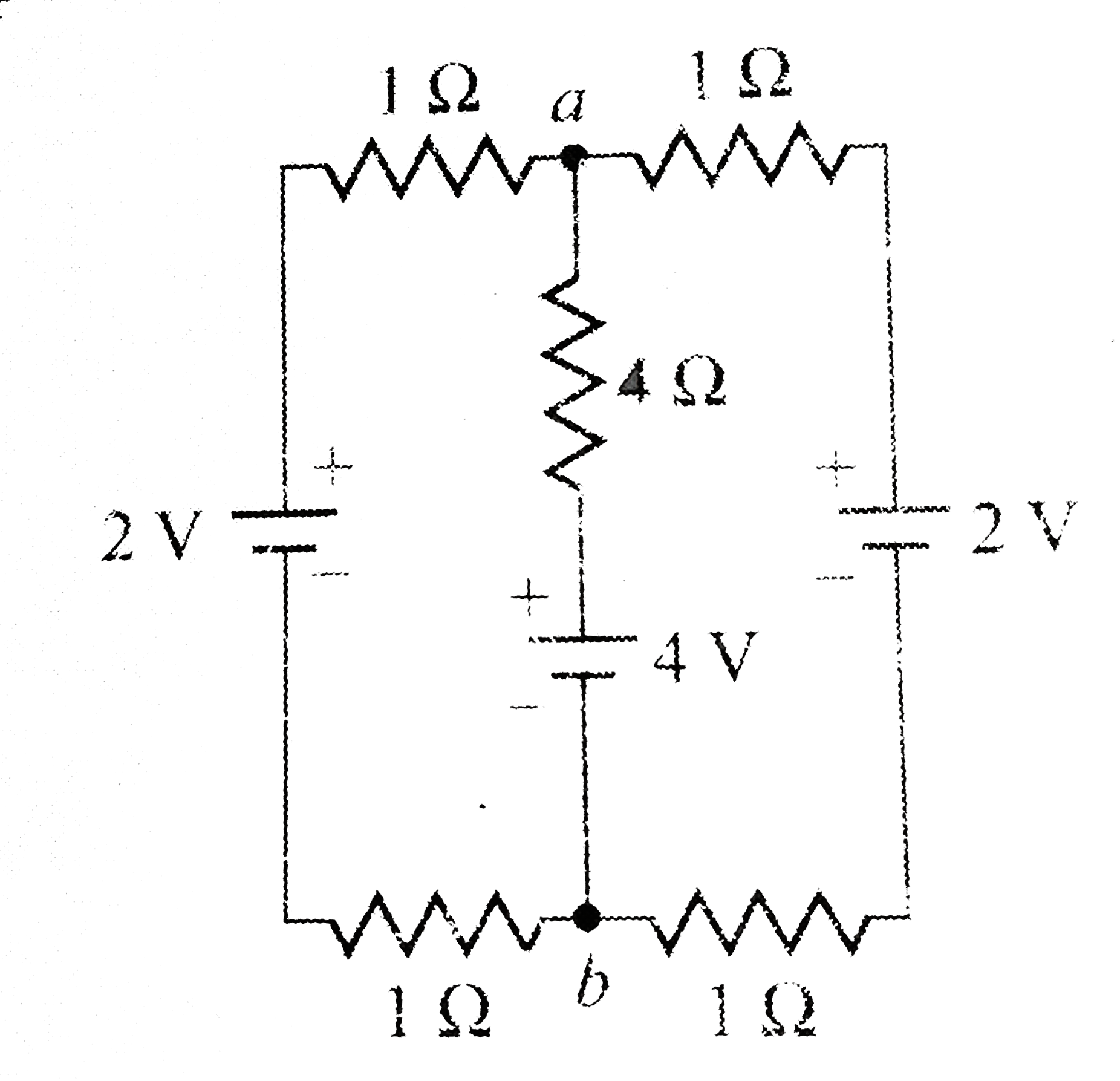
View SolutionFor the circuit in find the potential difference between points a and b.
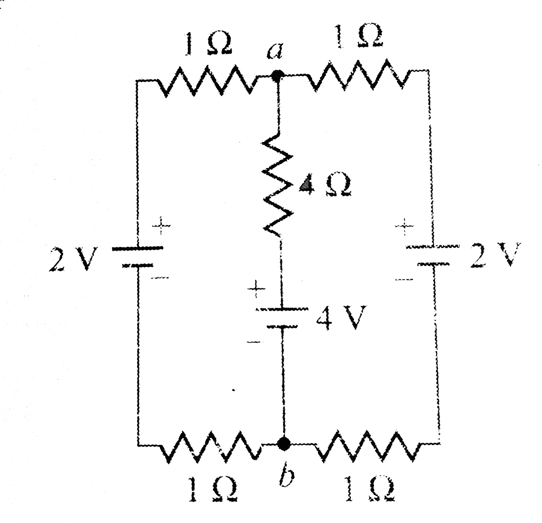
View SolutionFind the current in each resistor of the circuit shown in fig
a. Current thorugh resistance of `6 Omega is ………..`
b. Current thorugh resistance of `3 Omega is ………..`
c. Current thorugh resistance of `2 Omega is ………..`
d. Current thorugh resistance of `5 Omega is ………..`
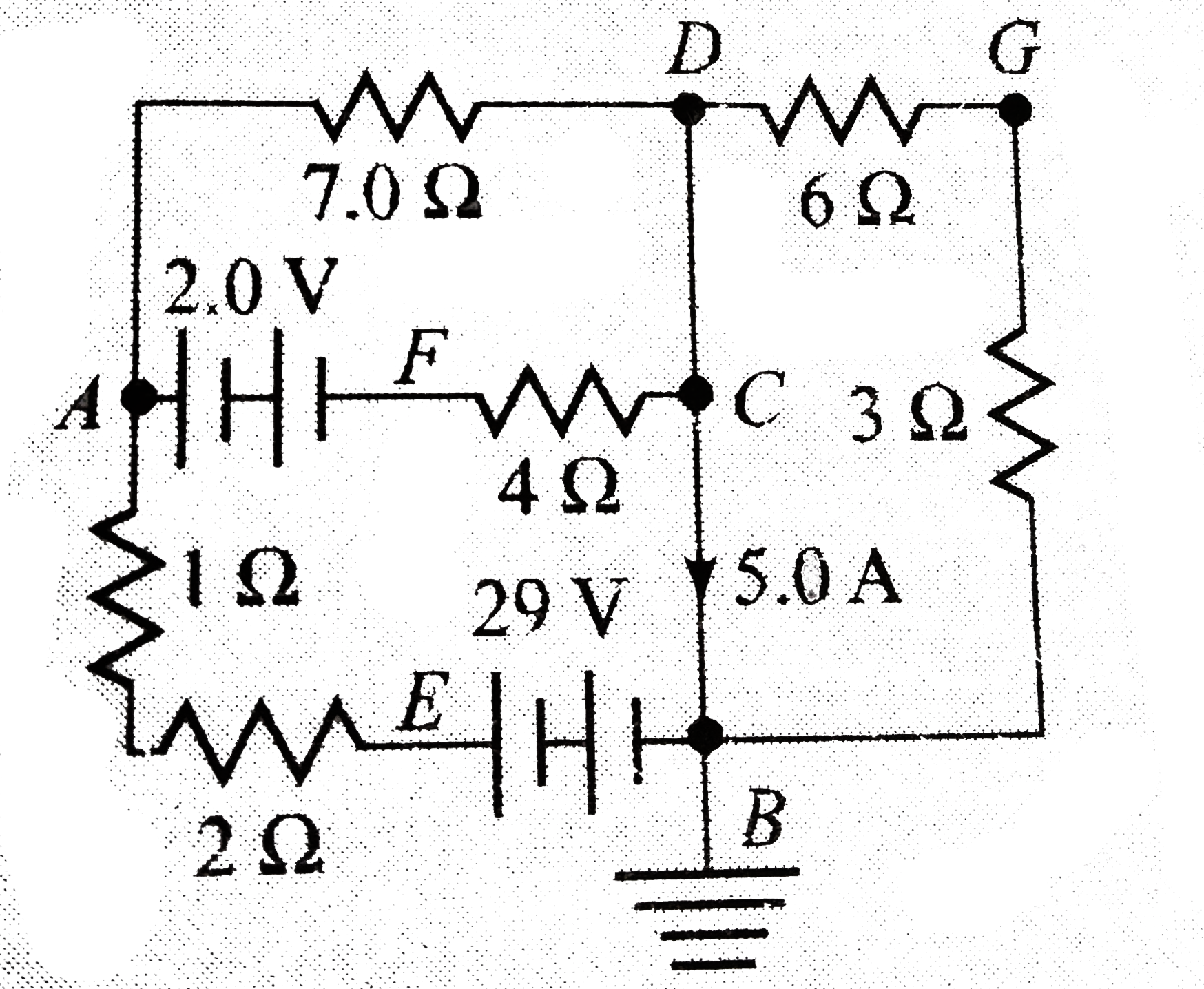
View SolutionGiven that a current of 5.0 A passes along the branch from C to B is fig What is the voltage of points A,D,and G? a. `V_A = …………` , b. `V_D = …………….` c. `V_G= …………..`
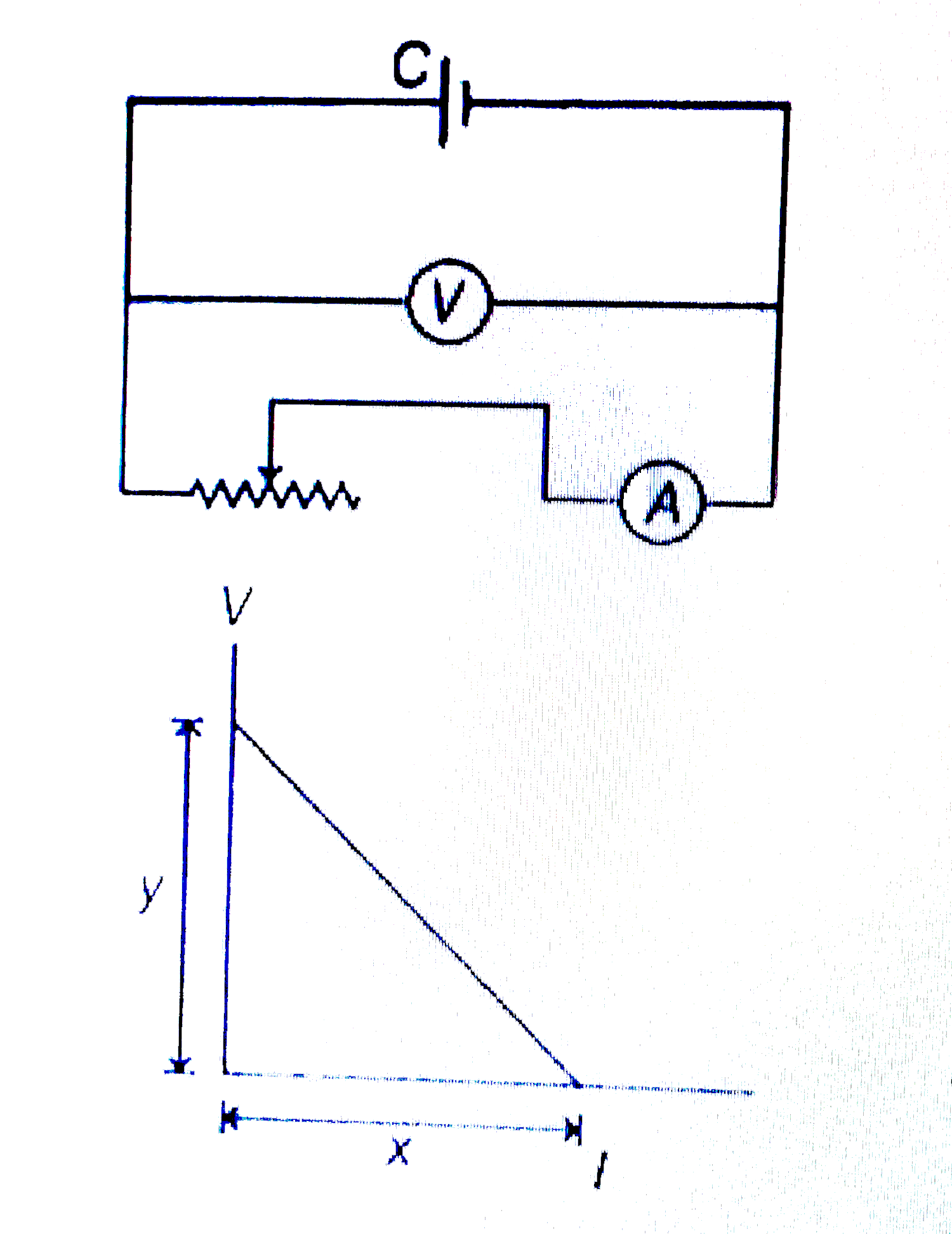
View SolutionThe diagram shows a circuit used in an experiment to determine the emf and internal resistance of the cell C. A graph was plotted of the potential difference V between the terminals of the cell against the current I, which was varied by adjusting the rheostat. What is the internal resistance of the cell?
View SolutionEach resistance in the circuit is of `2000 Omega.`
The combinatios is put across a supply of 200 V. Find the readng of ammeter.
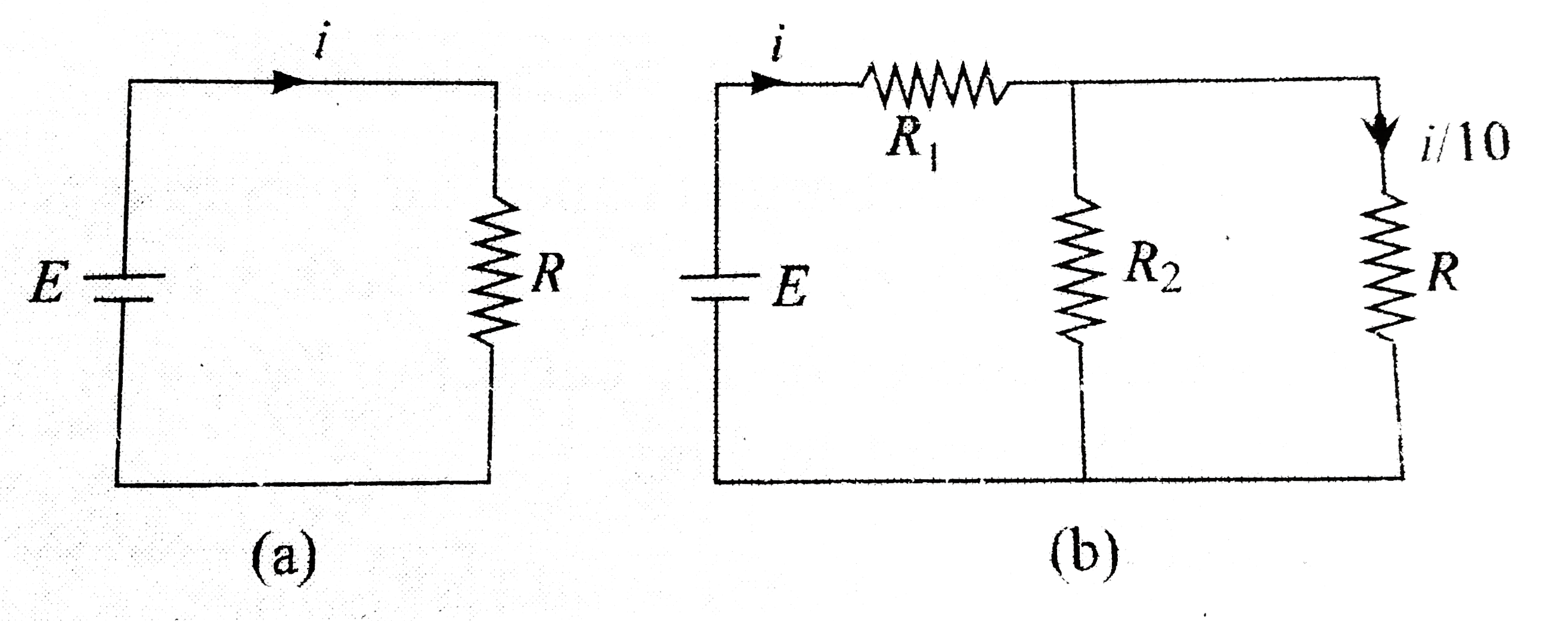
View SolutionConsider the circuits shown in fing Both the circuits are taking same current from the battery, but the current through R in the second circuit is 1//10 th of the current thourgh R in the first cirucit , if R is `11Omega` then find the value of `R_1 and R_2`
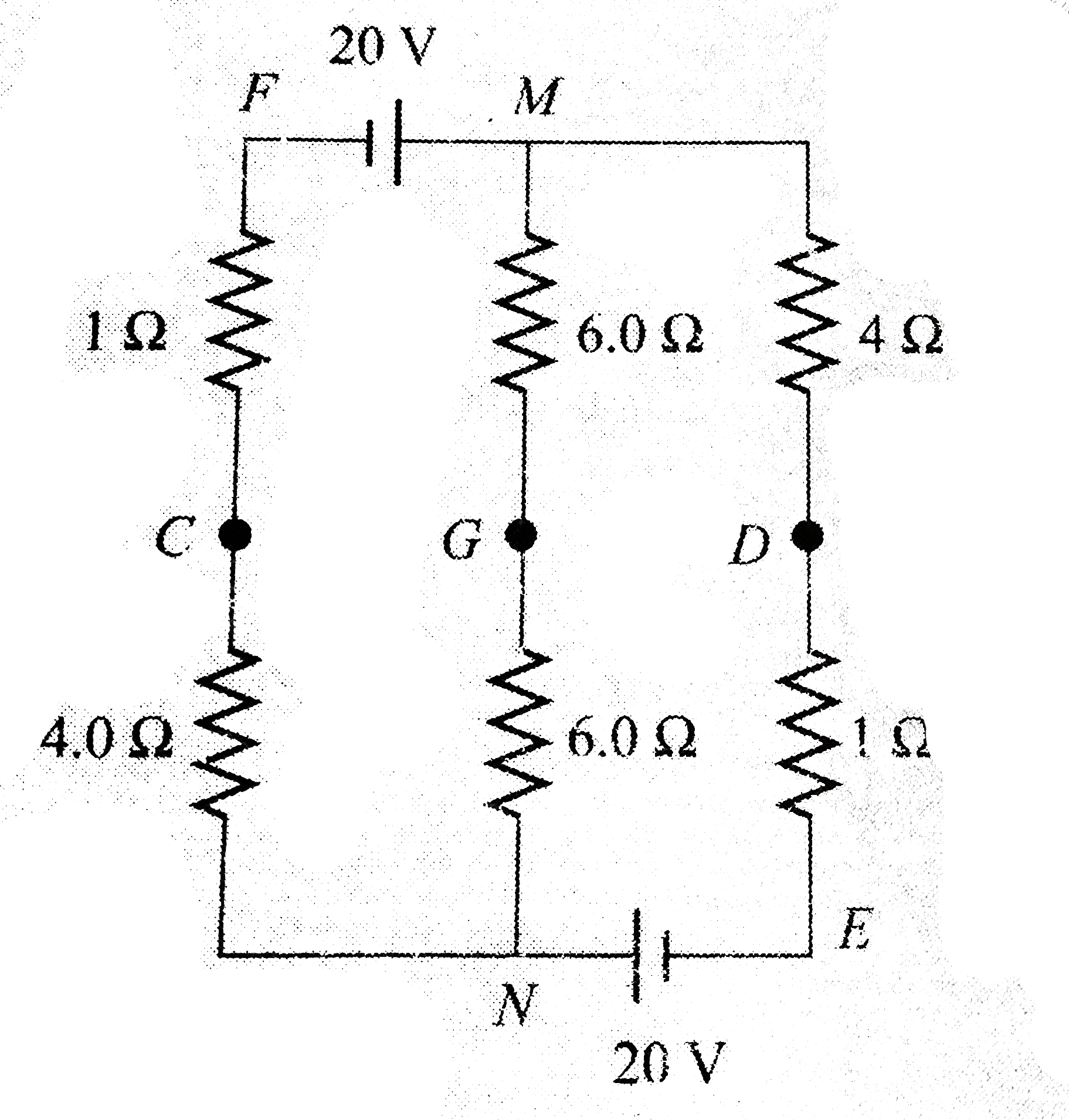
View SolutionCalculate the current through the resistance connected across MN and the current supplied by each of the batteries in the circuit diagram shown in

View SolutionIn this given figure find the equivalent resistance across AB.

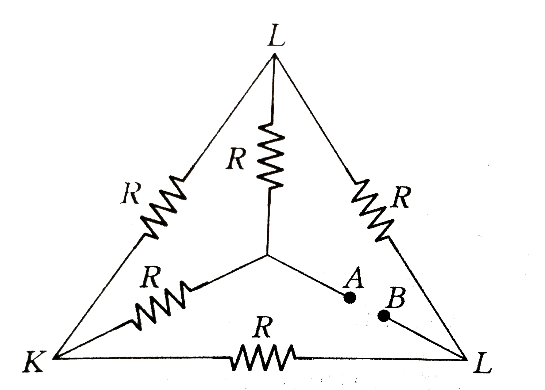
View SolutionEach of the resistance in the network shown in the figure is equal to R. The resistance between the terminals A and B is
View SolutionA battery of emf 2.0 volts and internal resistance `0.10(Omega)`is being charged with a current of 5.0A. What is the potential difference between the terminals of the battery?
View SolutionHow a battery is to be connected so that the shown rheostat will behave like a potential divider? Also indicate the points about which output can be taken.
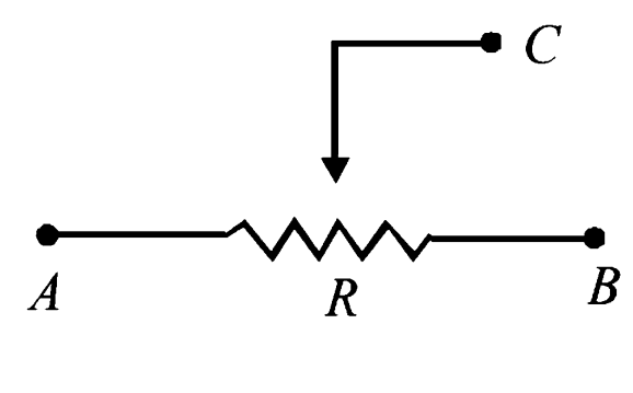 .
.
View SolutionIn the following circuit ,`E_1 = 4V, R_1 = 2 Omega,`
`E_2 = 6 V, R_2 = 2Omega, and R_3 = 4Omega.` Find the currents `i_1 and i_2`
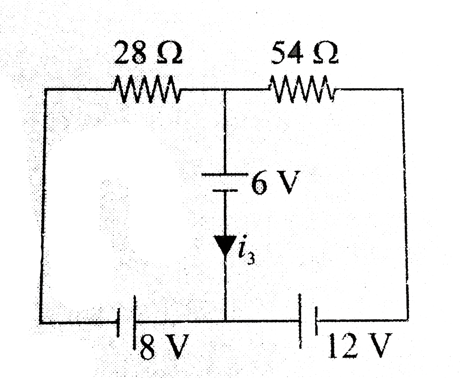
View SolutionConsider the cicutir shown in fig. the current `i_3` is equal to
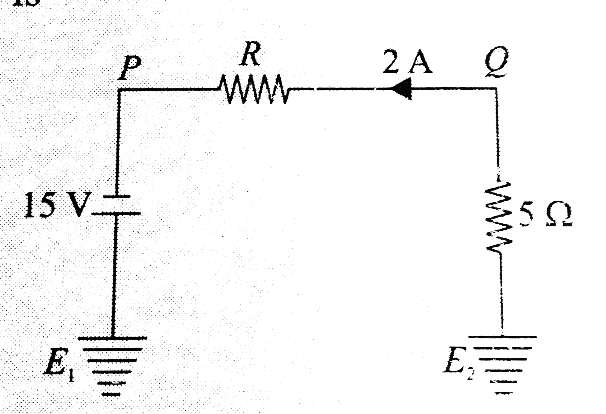
View SolutionIn the follwing circuit , the potential difference betweenn P and Q si
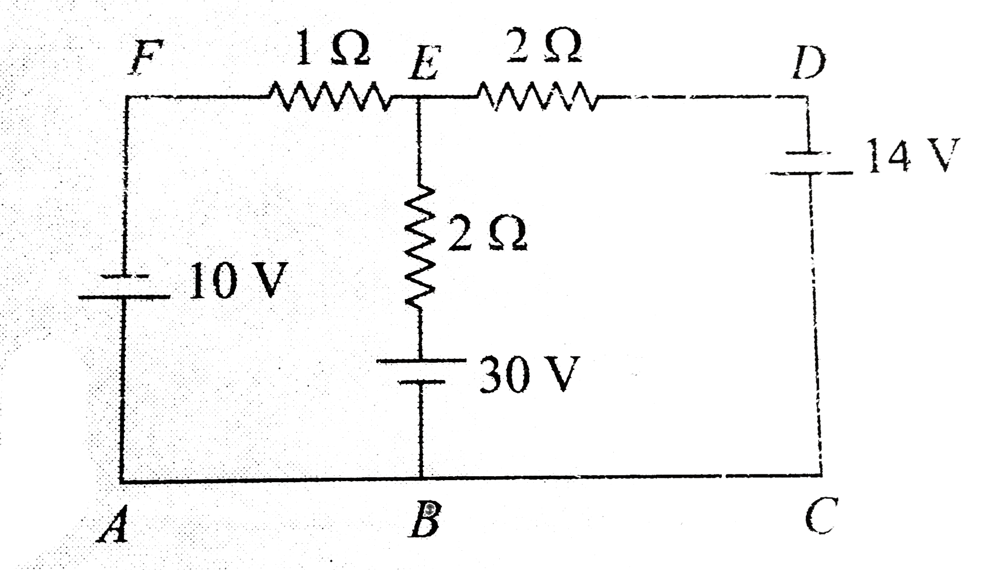
View SolutionFind the current in each wire.
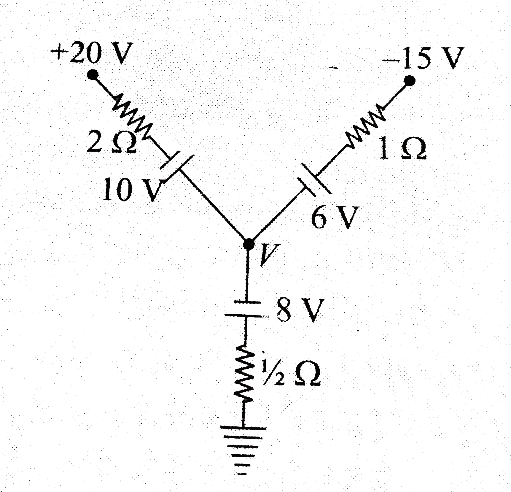
View Solutionin the network of three cells, find the potential V of their funcion.
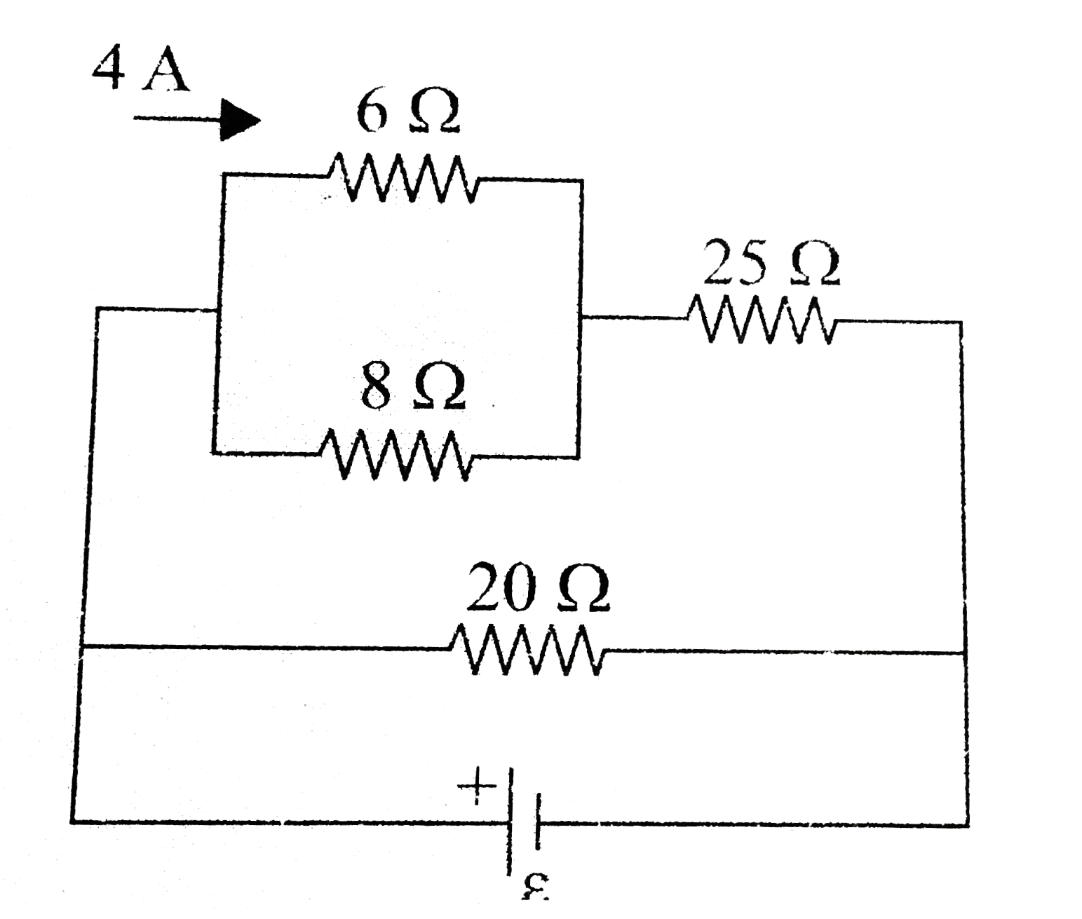
View SolutionIn the circuit shown in fig the voltage across the 2 Ω resistor is 12V. What is the emf of the battery and the current thorugh the 6 Ω resistor?
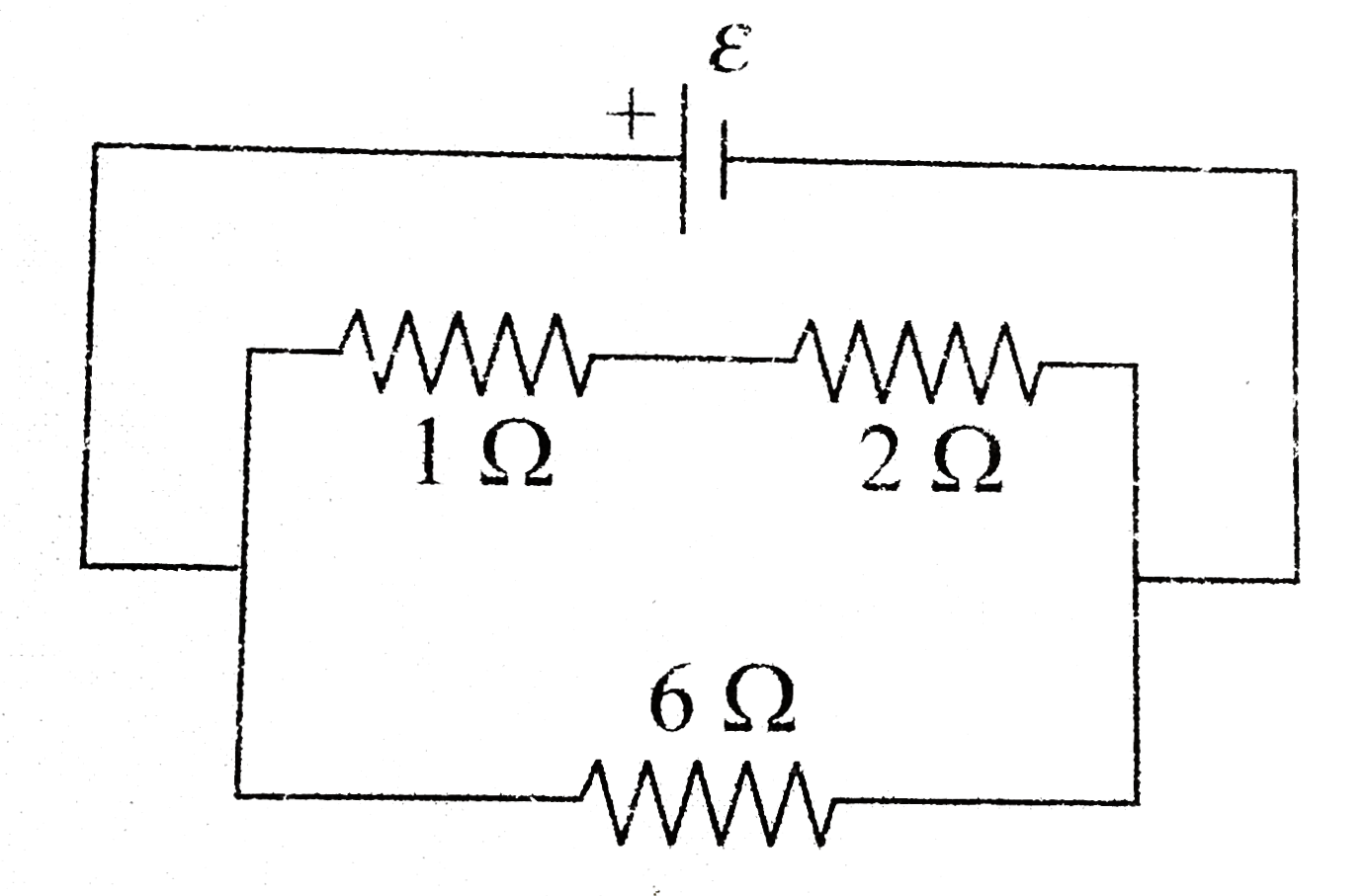
View SolutionIn the circuit shown in fig the voltage across the `6Omega` resistor is 12V. What is the emf of the battery and the current thorugh the `6Oemga` resistor?
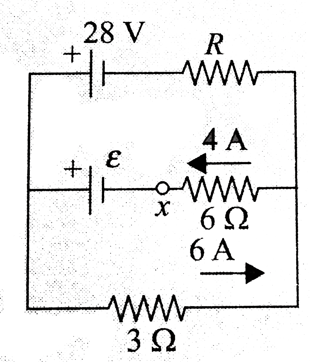
View SolutionIn the circuit shown in fig
a. find the current in resistor R
b. find the reistor R
c. find the the unkown emf `epsilon`
d. if the circuit is broken at point x,
what is the current in resistor R ?

View SolutionIn the circuit shown in figure find:
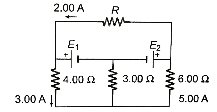
a. the current in the `3.00 Omega` resistor,b. the unknown emfs`E_1` and `E_2` and c the resistance `R`.
View SolutionIn the circuit shown in figure ,
a. find the current is each branch
b. find the potential difference `V_(ab)` of point a relative to point b.
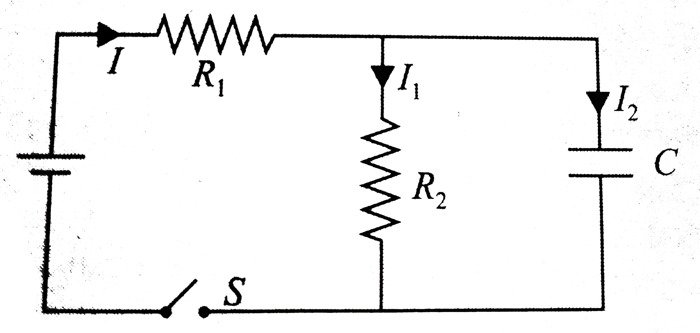
View SolutionConsider the circuit shown in fig. If the switch is closed at t =0, then calculate the values of `I, I_(1)` and `I_(2)` at a. t =0 , b. `= oo`
View SolutionShown three sections of the circuit that are to be connecte in turn to the same battery via a switch. The resistors are all identical, as are capactiors. Rank the sections according to
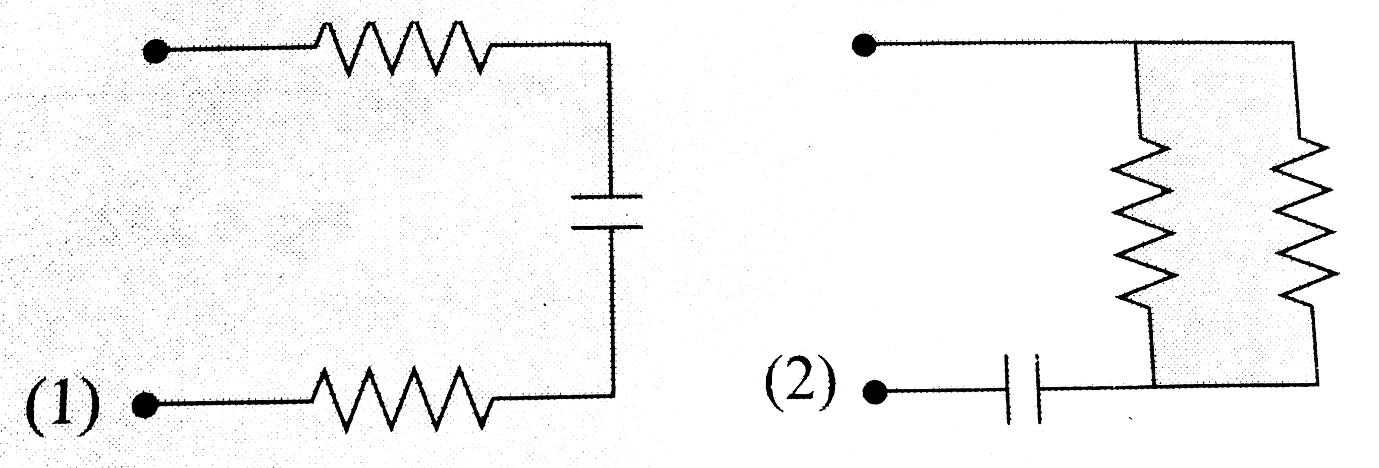
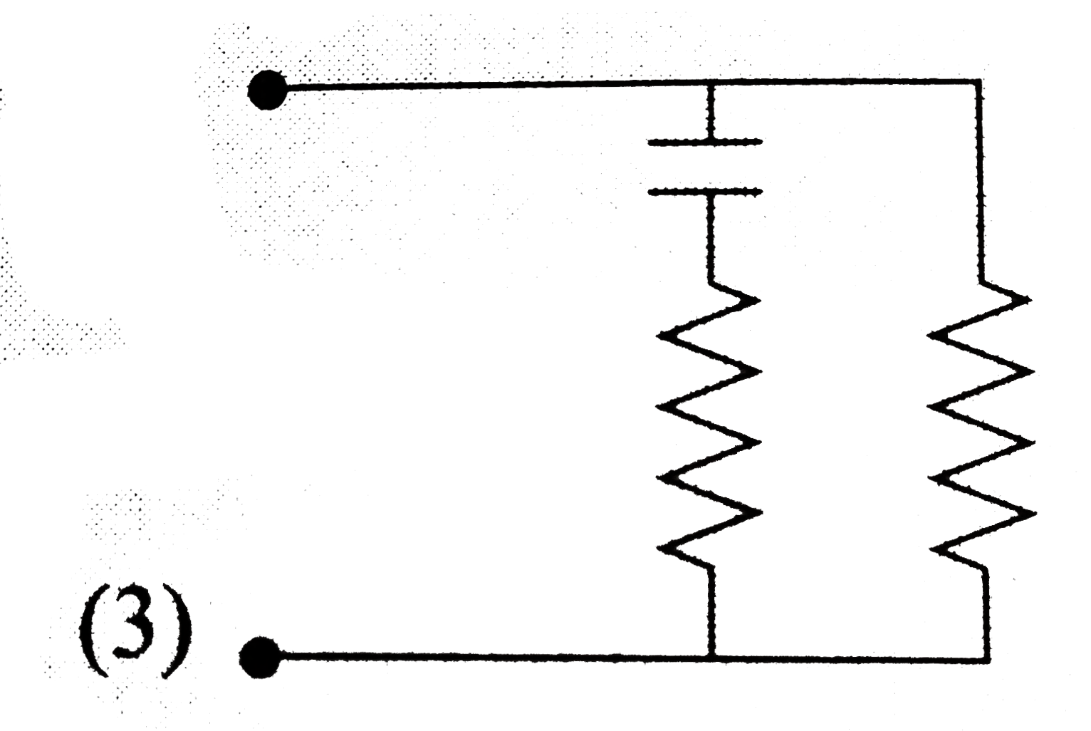
a. the final (equilibrium) charge on the capacitor.........
b. the time required for the capacitor to reah 50% of its final charge, greatest first.......
View SolutionDetermine the current through the battery in the circuit shown in figure.
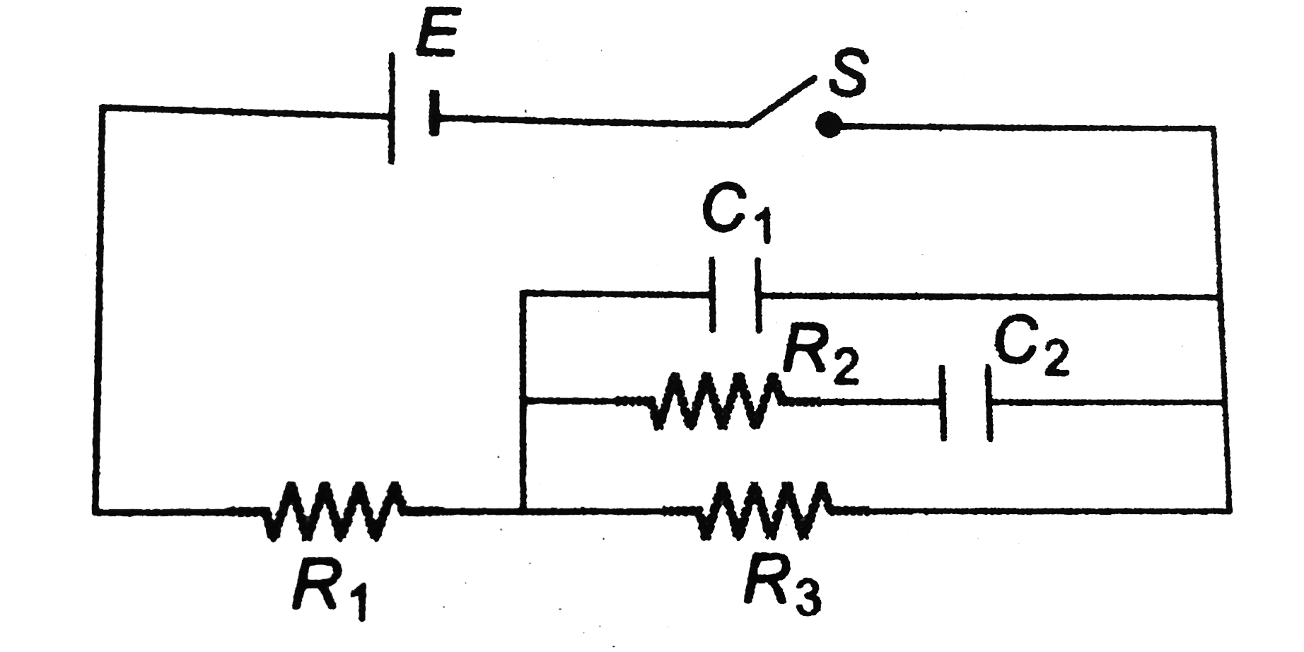
(a) immediately after the switch S is closed
(b) after a long time.
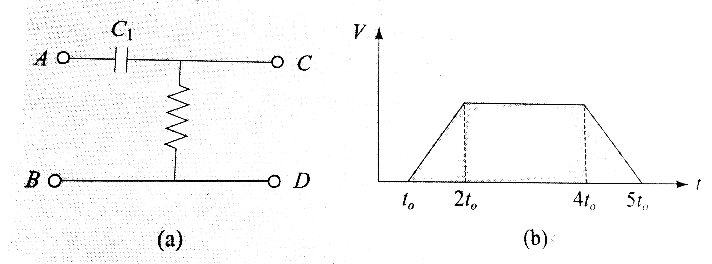
View SolutionA varying voltage is applied to the clamps AB as shown in fig. such that the voltage across the capacitor plates varies as shown in the figure. Plot the time depending on voltage across the clapes CD.

View SolutionConsider the network shown in initially, the switch `S_(1)` is closed and `S_(2)` is open.
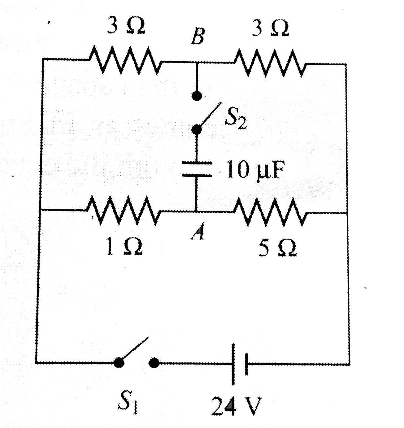
a. Calculate `V_(A) - V_(B).`
b. When `S_(2)` is also closed, what is `V_(A) - V_(B)`
i. just after closing , ii. After long time.
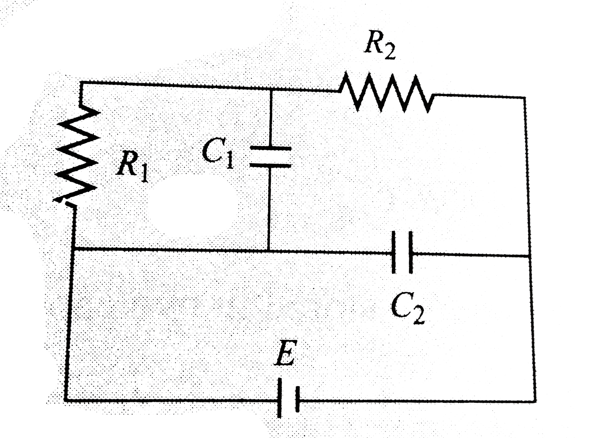
View SolutionIn the circuit shown in fig. `R_(1) = 10 Omega, R_(2) = 5 Omega, C_(1) = 1 muF, C_(2) = 2muF,` and E =6V. Calculate the charge on each capactor in the stedy state.
View SolutionIn the circuit shown in fig switch S is closed at time t =0.
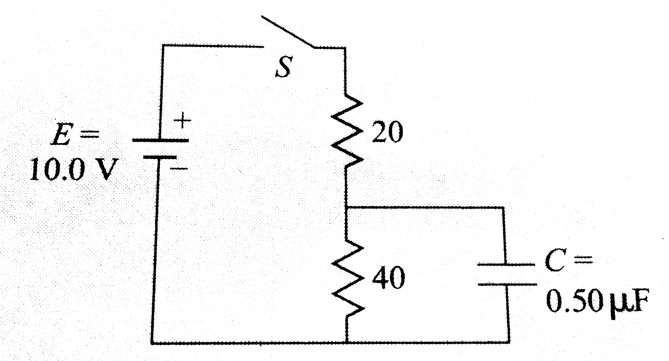
a. What is the current `I_(0)` leacing the battery at t=0, immediately after the switch is closed?
b. What is the current I "long time" later?
c. What charge has accmulated on the capacitor after this long time?
d. If, finally, swtich S is opened again, how long will it take after the switch is opened for the capactior to lose 80% of its charge?
View SolutionThe plates of a `50(mu)F` capacitor charged to `400(mu)C` are connected through a resistance of `1.0k(ohm)`. Find the charge remaining on the capacitor 1s after the connection is made.
View SolutionThe electric field between the plates of a parallel-plate capacitor of capacitance`2.0(mu)F` drops to one third of its initial value in `(4.4 mu)s` when the plates are connected by a thin wire. Find the resistance of the wire.
View SolutionThe time constant of and R- C cirucit during charging is them time in which the charge on the condenser plates, as compared to maximum charge `(q_0)` becomes `(q//q_0)xx `100,` which is equal to …….. .
View SolutionHow many time constants will elapse before the energy stored in the capacitor reaches half of its equilibrium value in a charging RC circuit ?
View SolutionHow many time constant will elapse before the power delivered by the battery drops to half of its maximum value in RC circuit.
View SolutionA capacitor of capacitance C is given a charge Q. At `t=0`,it is connected to an uncharged of equal capacitance through a resistance R. Find the charge on the second capacitor as a function of time.
View SolutionIn charging singe loop R - C circuit, after how many time constant, the potential energy in the capacitor will be 25% of its maximum value.
View Solution
Exercise 5.2 questions and complete solutions for chapter ELECTRIC CURRENT AND CIRCUIT of CENGAGE PHYSICS (ENGLISH) of Class 12