Complete Solutions to Subjective of chapter ELECTRIC CURRENT AND CIRCUIT of Class 12 book with complete answers and questions
| Class 12 | PHYSICS |
| Chapter | ELECTRIC CURRENT AND CIRCUIT |
| CENGAGE PHYSICS | Subjective |
| Number Of Questions | 29 |
| Academic Year | 2023-24 |
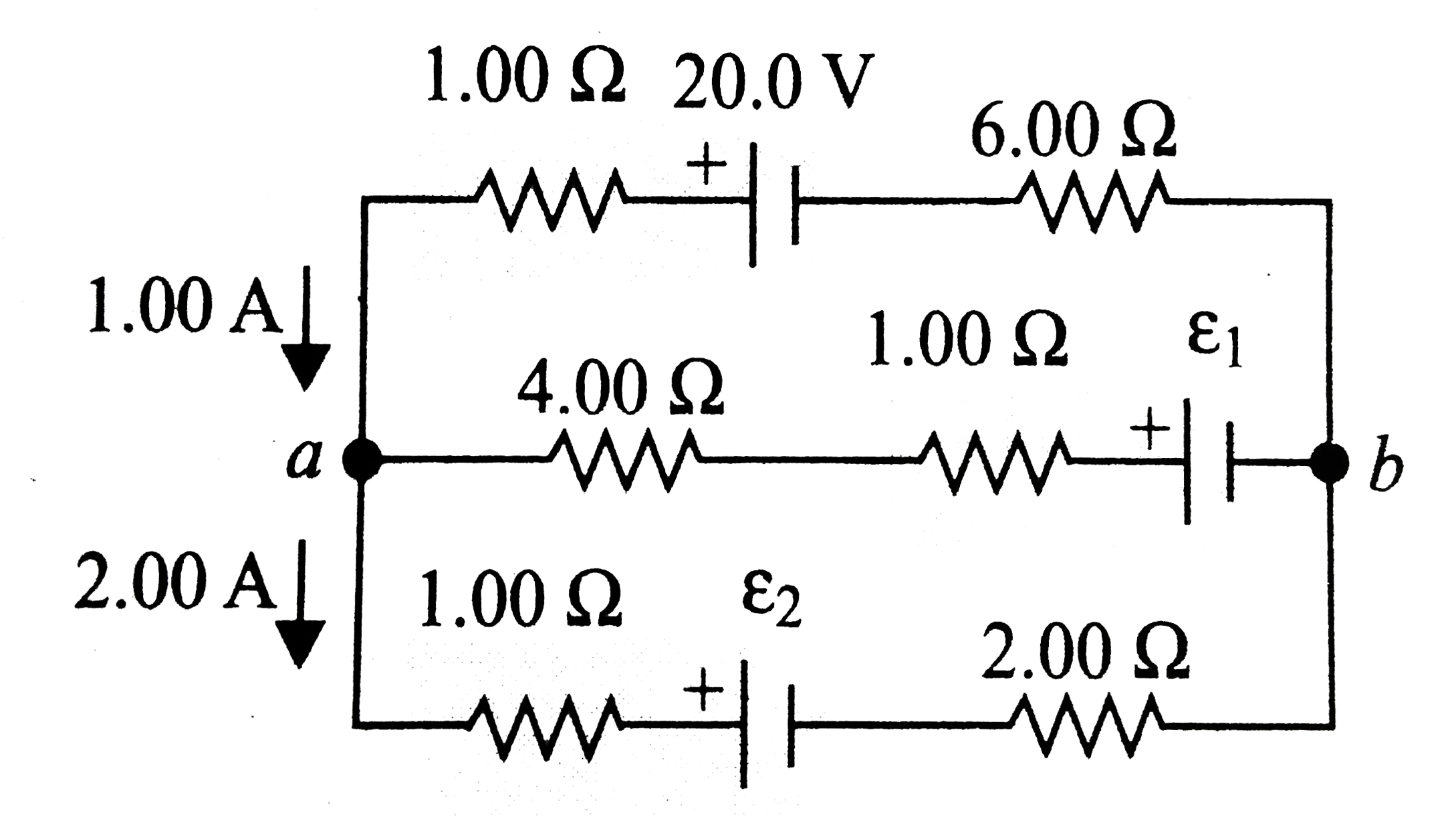
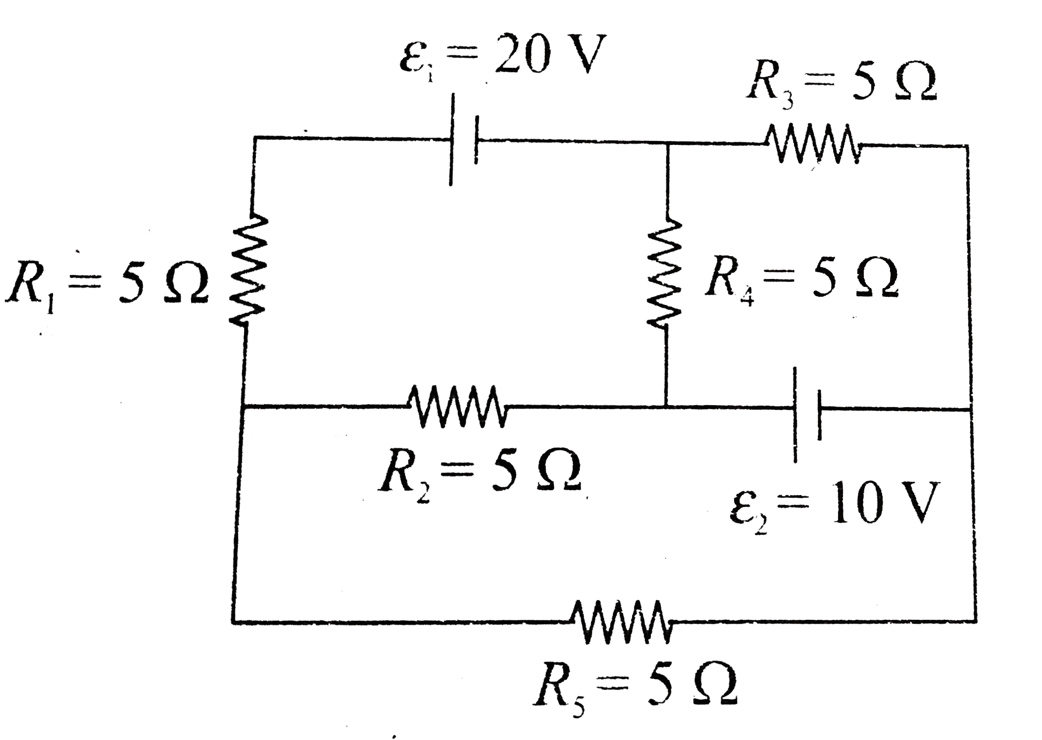
find the emfs `epsilon_1 and epsilon_2` in the cirucit in fig also find the potetial differece of point b relative to point a.
View SolutionAt room temperature `(27.0 .^(@)C)` the resistance of a heating element is `100 Omega`. What is the temperature of the element if the resistance is found to be `117 Omega`, given that the temperature coefficient of the material of the resistor is `1.70 xx 10^(-4) .^(@)C^(-1)`.
View SolutionA platinum wire has a resistance of `10Omega at 0^@C and 20Omega at 273^@C.` find the value of temperaure cofficient of platinum.
View SolutionA metal wire of dimeter 4mm and length 100 m has a resistacne of `0.408 Omega at 10^@ and 0.508Omega at 120^2 C` find the value of
a. temperature cofficinet of resistance
b. its resistivities of `0^@C and 120^@C`
View SolutionA storage battery of emf 8.0 V and internal resistance `0.5 Omega` is being charged by a 120 V dc supply using a series resistor of `15.5 Omega`. What is the terminal voltage of the battery during charging? What is the purpose of having a series resistor in the charging circuit?
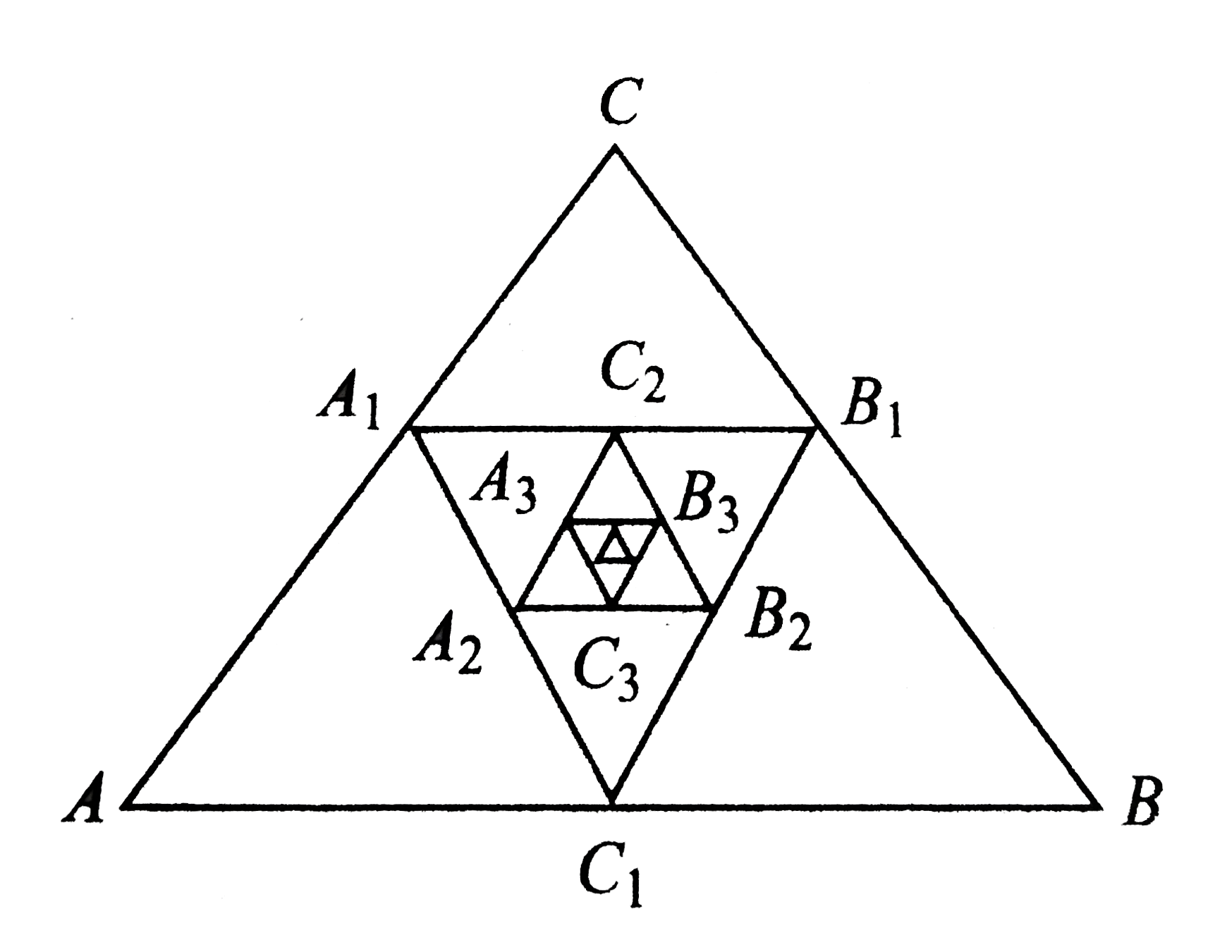
View SolutionFind the resistacne `R_(AB)` of the frame made of a thin wire. Assume that the number of successively embedded equilateral triangles (with sides decrasing ot half) tends to infifity Side AB is equal to a, and the resistance per unit length of wire is `lambda.`
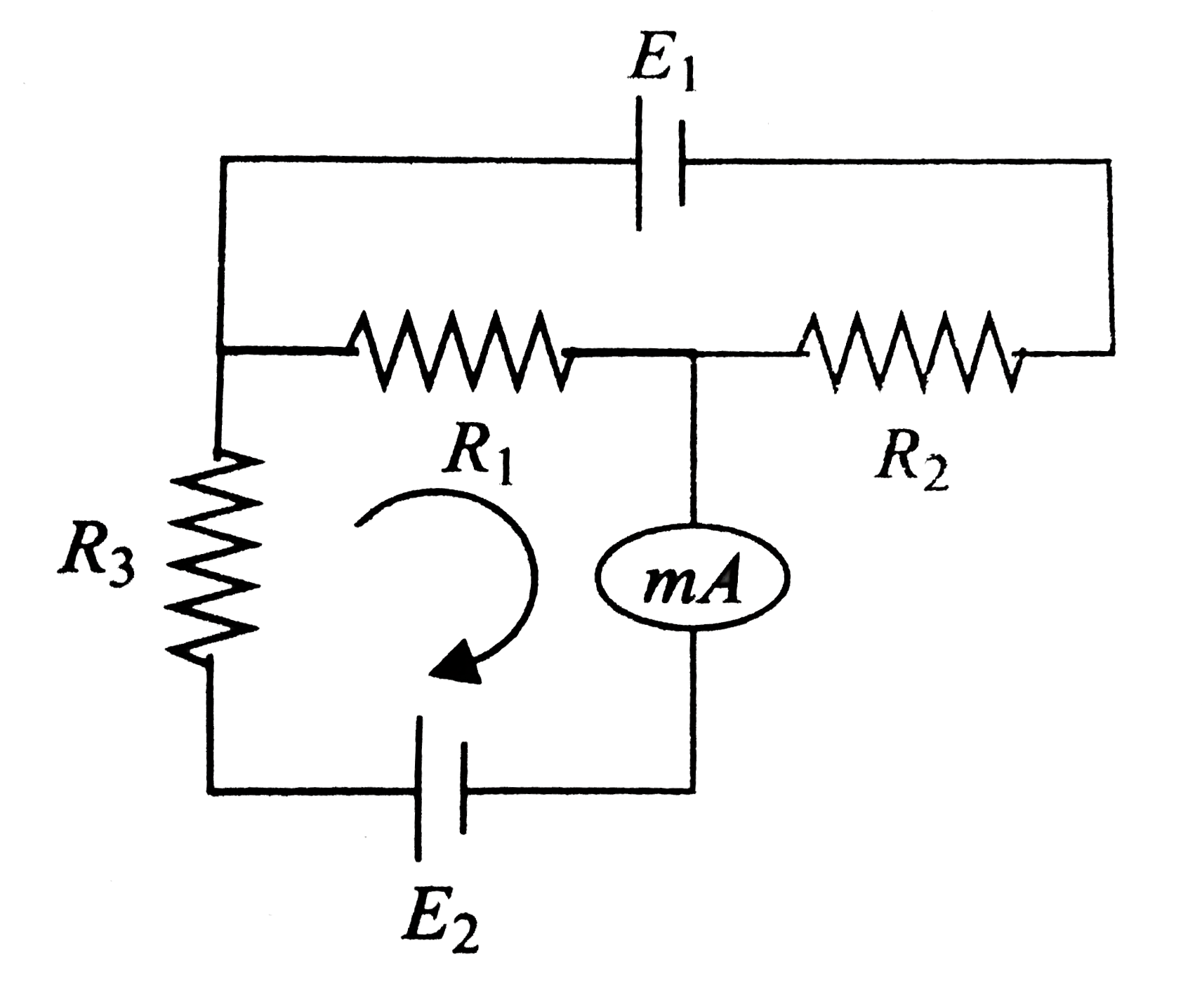
View SolutionThe circuit shown in fig 5.230 contains three resistors `R_1 =100Omega, R =50Omega` and `R_3 =20Omega` and cells of emfs `E_12V and E_2` The ammeter indicates a current of 50mA. Determina the currents in the resistors and the emf of the second cell. The internal resistance of the ammeter and of the cells shoudl be
View SolutionIn the given circuit in Fig. all batteries have emf 10V and internal negligble. All resitors are in ohm Calcualte the current in the rightmost `2Omega` resistor.

View SolutionIn the circuit diagram shown in find the current through the `1Omega` resistor.

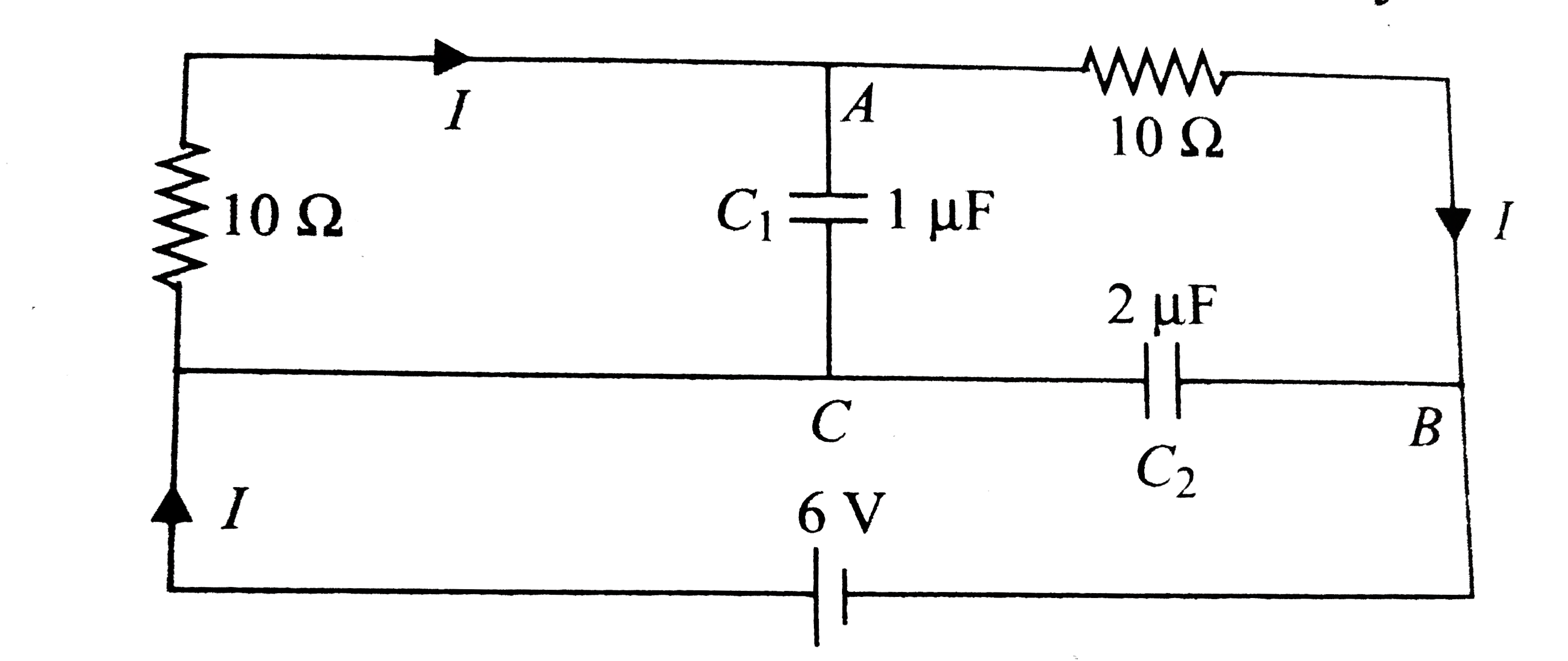
View SolutionThe circuit shown in fig 5.223 is in steady state.
find the charges on the capacitors `C_1 and C_2` respectively.
View SolutionConsider an infinita ladder of network shown In fig 5.223A voltage is applied between points A and B. If the voltage is havled after each seciton, find the raito of `R_1//R_2`

Suggest a method to terminate it after a few sections without introducing much error in its attenuation.
View SolutionFor a circuit shown in figure 5.235 switch `S_1` is closed at t= 0, then at `t = (2R_2+R_1)C, S_1` is opened and `S_2` is closed.
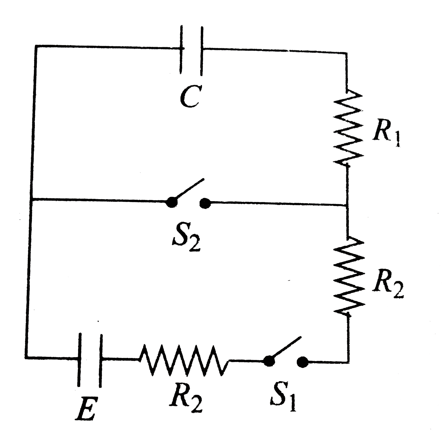
a. Find the charge on capactior at `t = (2R_2 + 2R_1)C.`
b. Find current through `R_2` (adjacent to the battery) at `t = (3R_1 +2R_2)C.`
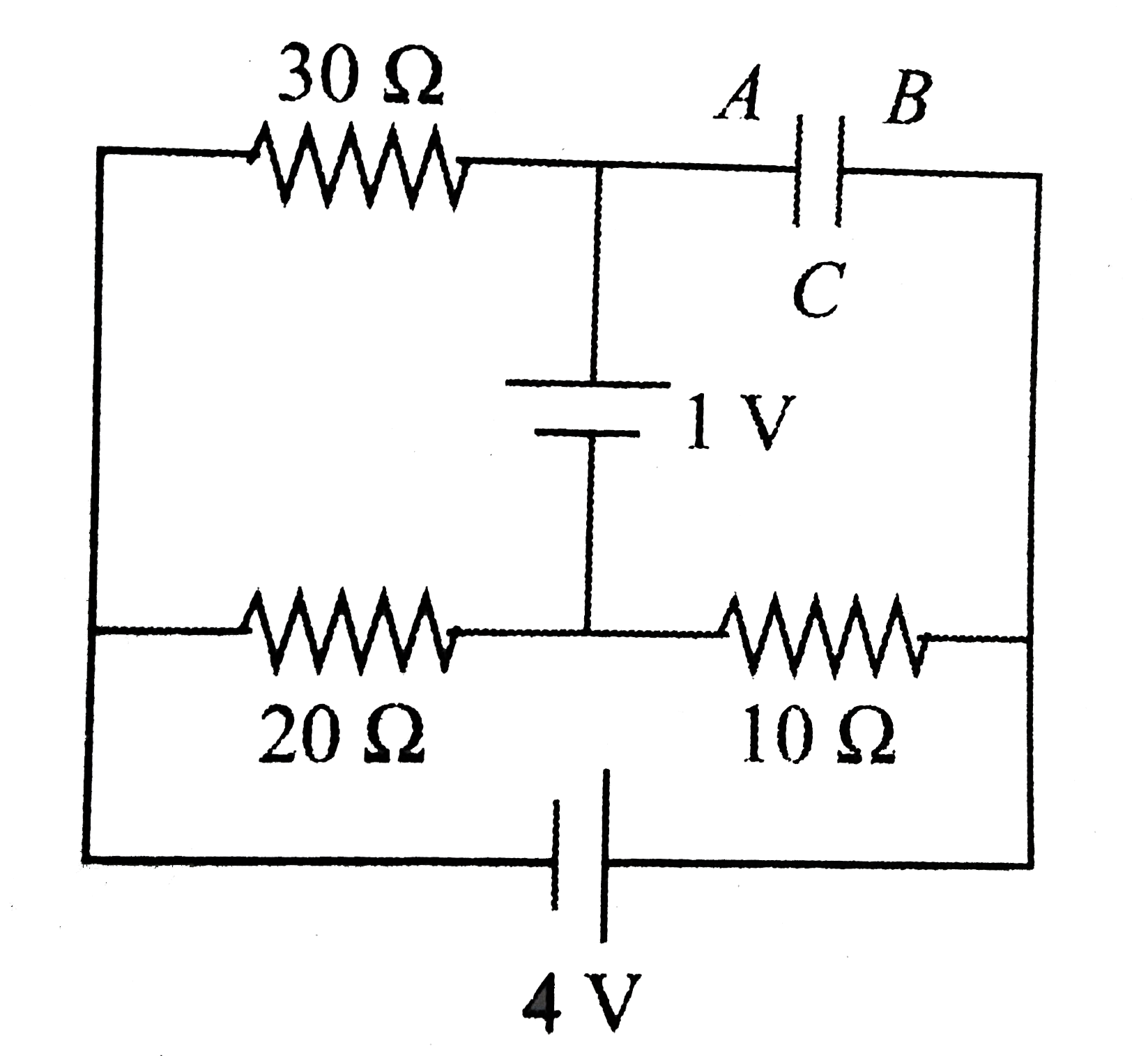
View SolutionFind the potential difference between the plates of the capactior C in the circuit shown in fig.5.236
View SolutionAnalyze the given circuit in the steady state condition. Charge on the capacitor is`q_0=16muC`
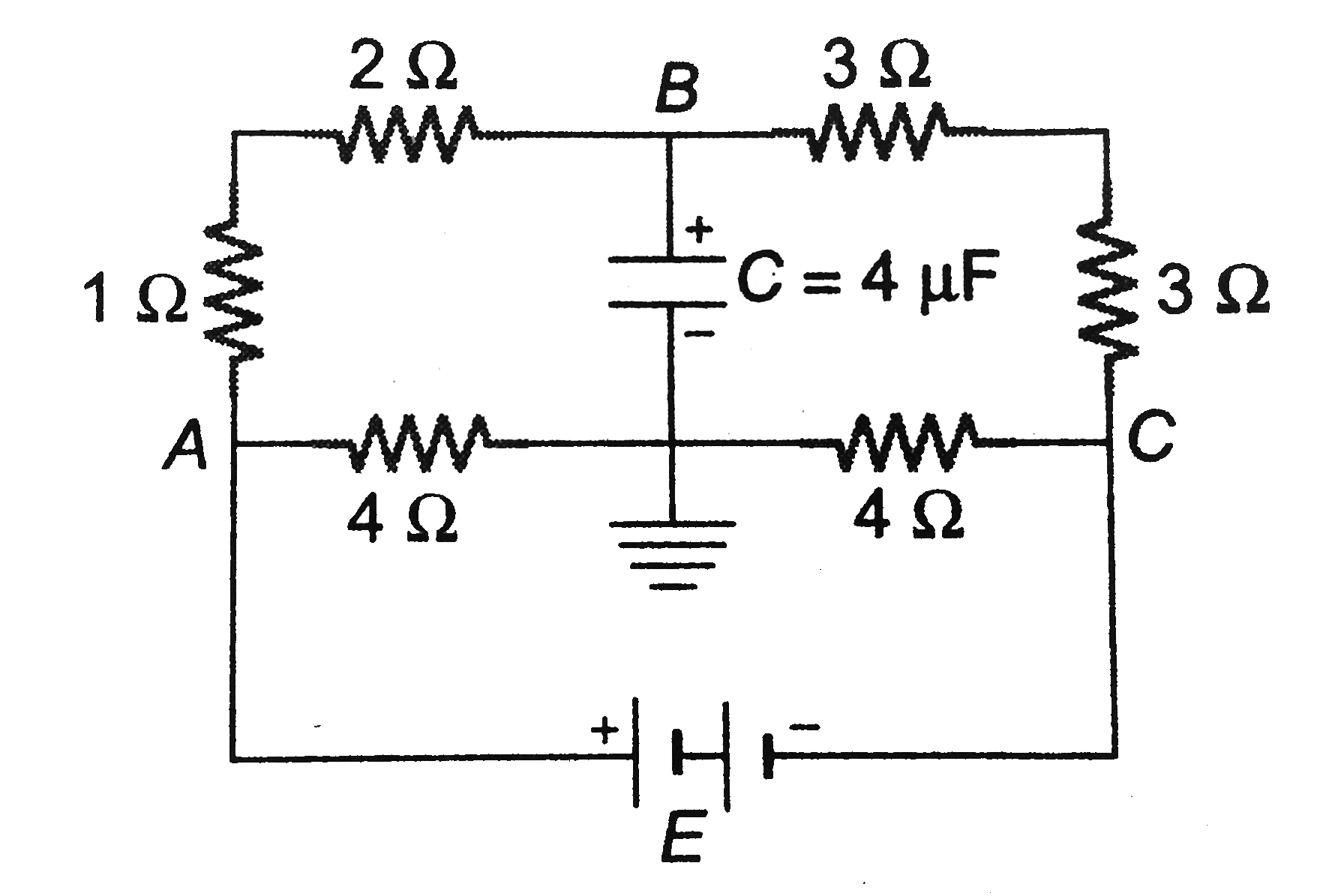
(a) Find the current in each branch
(b) Find the emf of the battery.
(c) If now the battery is removed and the points `A` and `C` are shorted. Find the time during which charge on the capacitor becomes
`8muC`
View Solution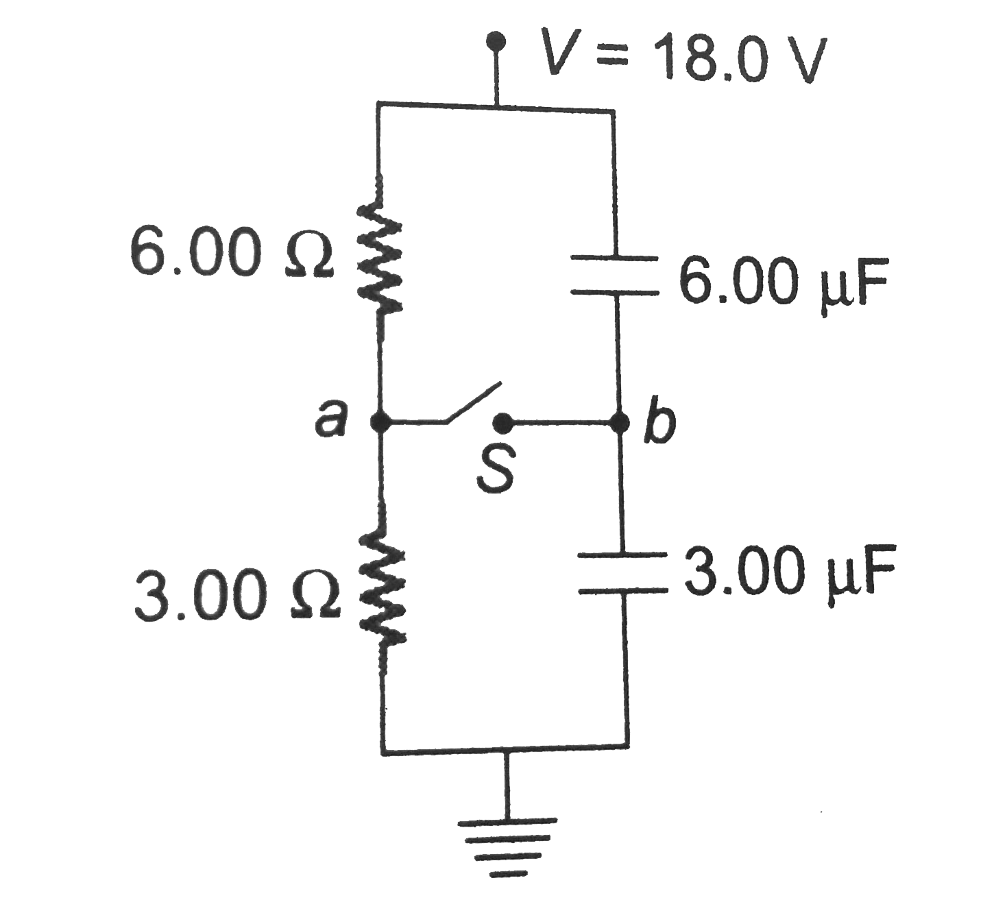
(a) What is the potential of point a with respect to point b in figure, when switch `S` is open?
(b) Which point, `a` or `b`, is at the higher potential?
(c) What is the final potential of point `b` with respect to ground when switch S is closed?
(d) How much charge flows through switch `S` when it is closed?
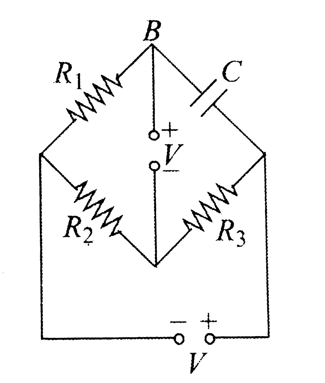
View SolutionIn the cicuit shown in fig. C is a parallel plate air capacitor having plate of area `A = 50cm^2` each and distance d = 1mm apart. `R_1 R_2, and R_3` are resistors having resistance `3Omega, 2Omega, and 1Omega` respectively. Two identical sources each of emf V and of emf V and of negligible internal resistance are connected as shown in fig. if a dielectric strength of are is `E_0 = 3xx10^6Vm^(-10)`, calculate the maximum safe value of V.
View SolutionThe circuit shown in fig. Is in steady state.
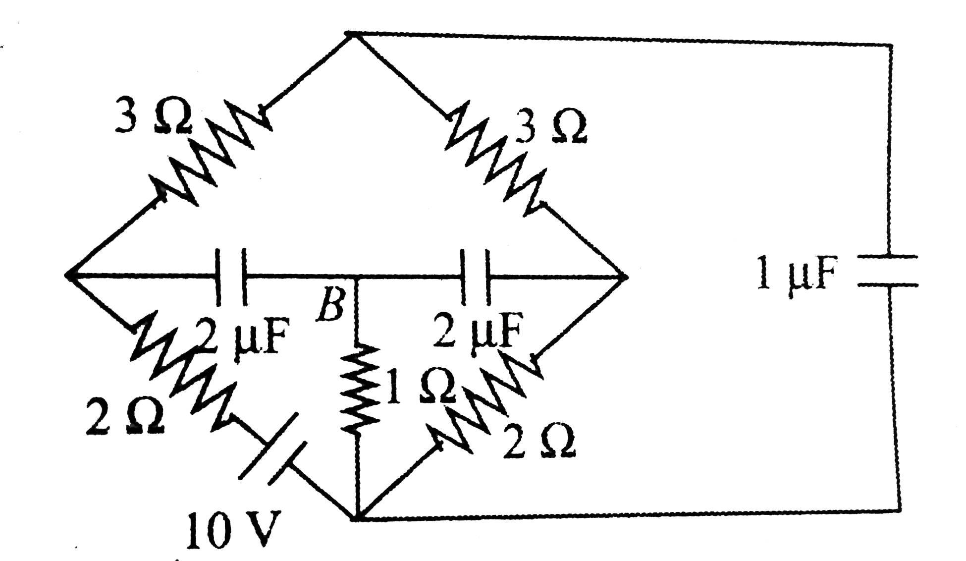
i. Find the energy stored in the capacitors shown in fig.
ii. Find the rate at which battery supplies energy.
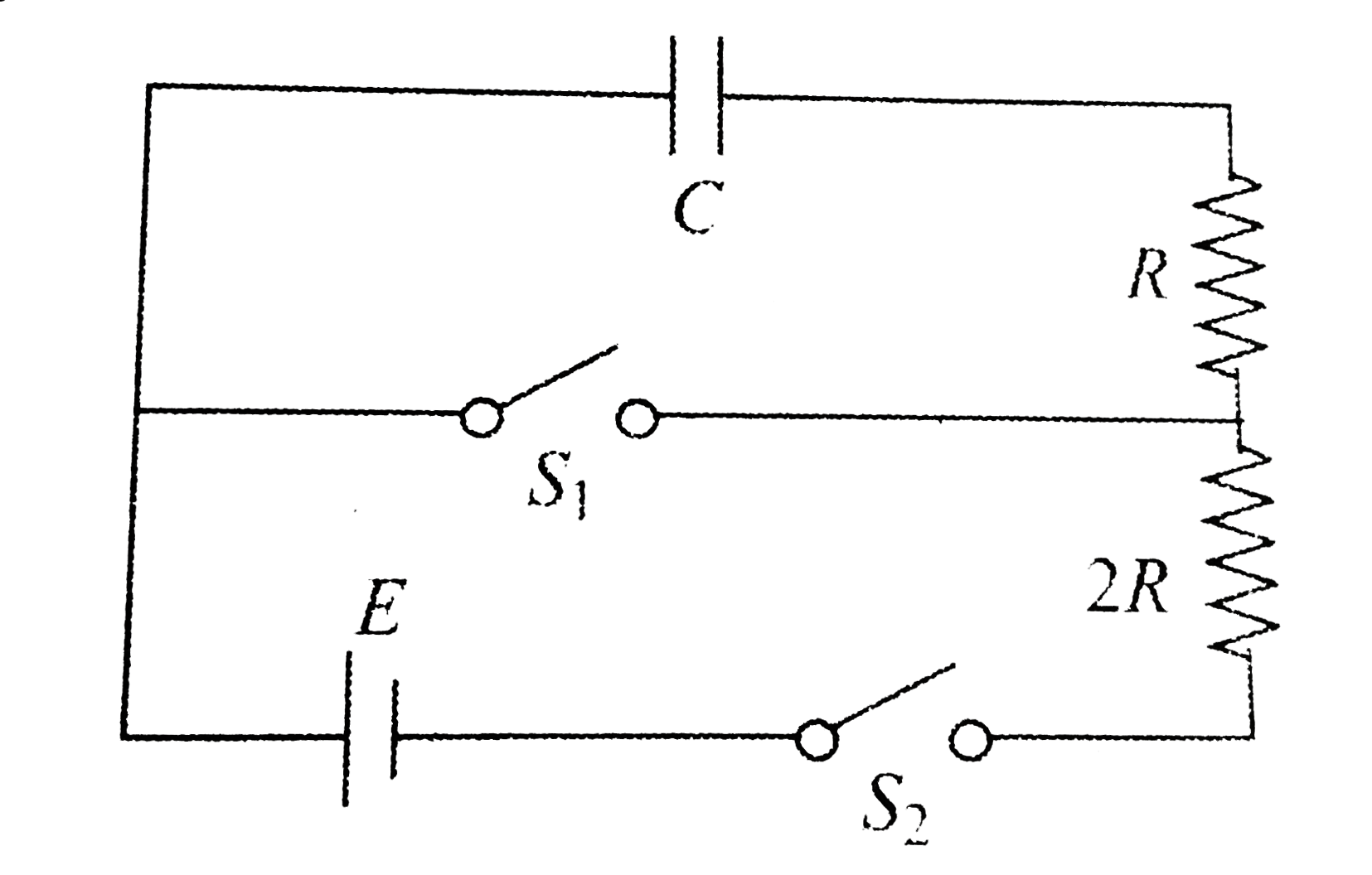
View SolutionThe given R-C circuit has two swithes `S_1 and S_2` Swithc `S_2` is clsoed and `S_1` is open till the capacitor is fully charged to `q_0` the `S_2` is opened and `S_1` is closed simultaneously till the charge on capacitor remains `q_0//2` for which it takes time `t_1`. Now `S_1` is again opened, and `S_2` is closed till chrage on capacitor becomes `3q_0/4`. it takes time `t_2` (see fig for referecne). Find the raito `t_1//t_2`
View SolutionFor the circuit arrangement shown in fig.
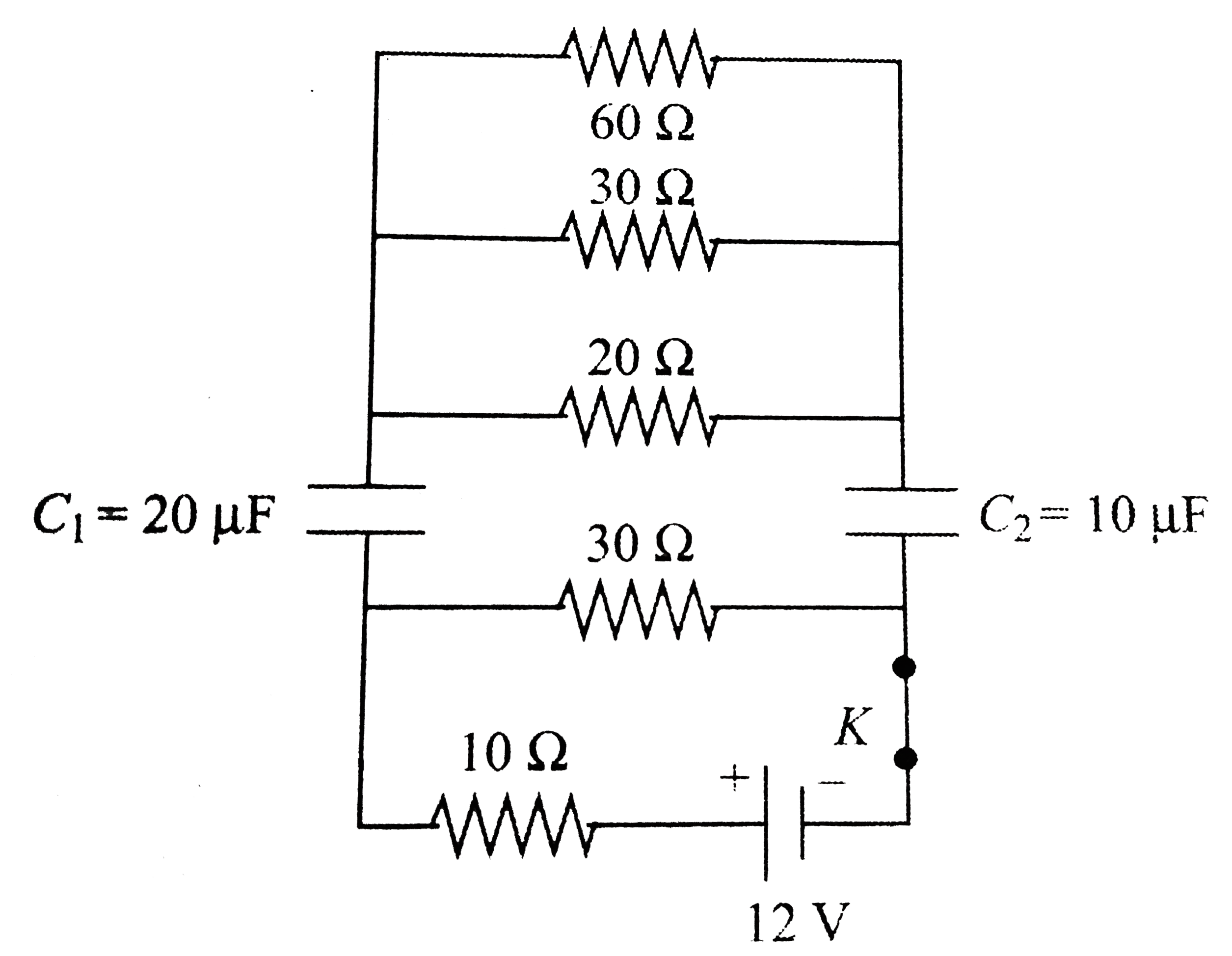
a. Find the potentail difference across each capacitor in the steady - state condition.
b. Find the current through the `60Omega` resistor just after the instant when the key K is opened.
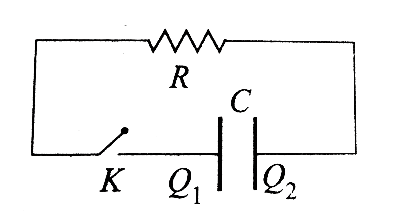
View SolutionThe plates of a capacitor of capacitance C are given the charges `Q_1 and Q_2` as shown in figure. Now the switch is closed at t =0. Find the charges on plates after time t.
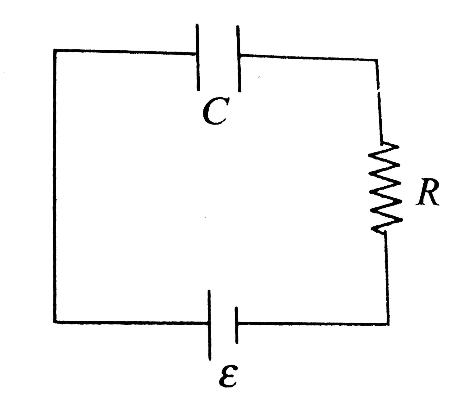
View SolutionConsider a parallel pate capacitor of capactance C with partially conducting medium between its plates having a resistacne `R_c` if this capacitor is connected to a battery of emf `epsilon` and a resistor R as shown in fig.
a. charge on the capacitor as a function of time.
The switch R as a function of time.
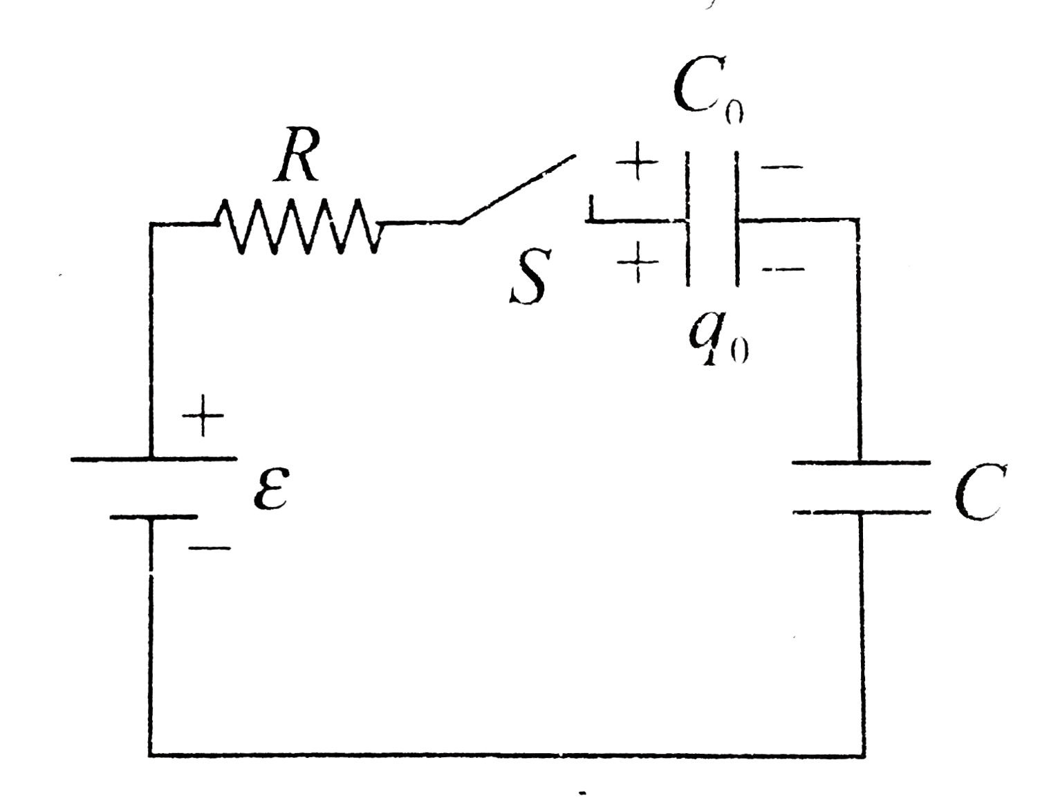
View SolutionThe switch S is closed aty t = 0. the capacitor C is uncharged but `C_0` has a charge `q_0` at t =0. Calculate the current i(t) in the circuit
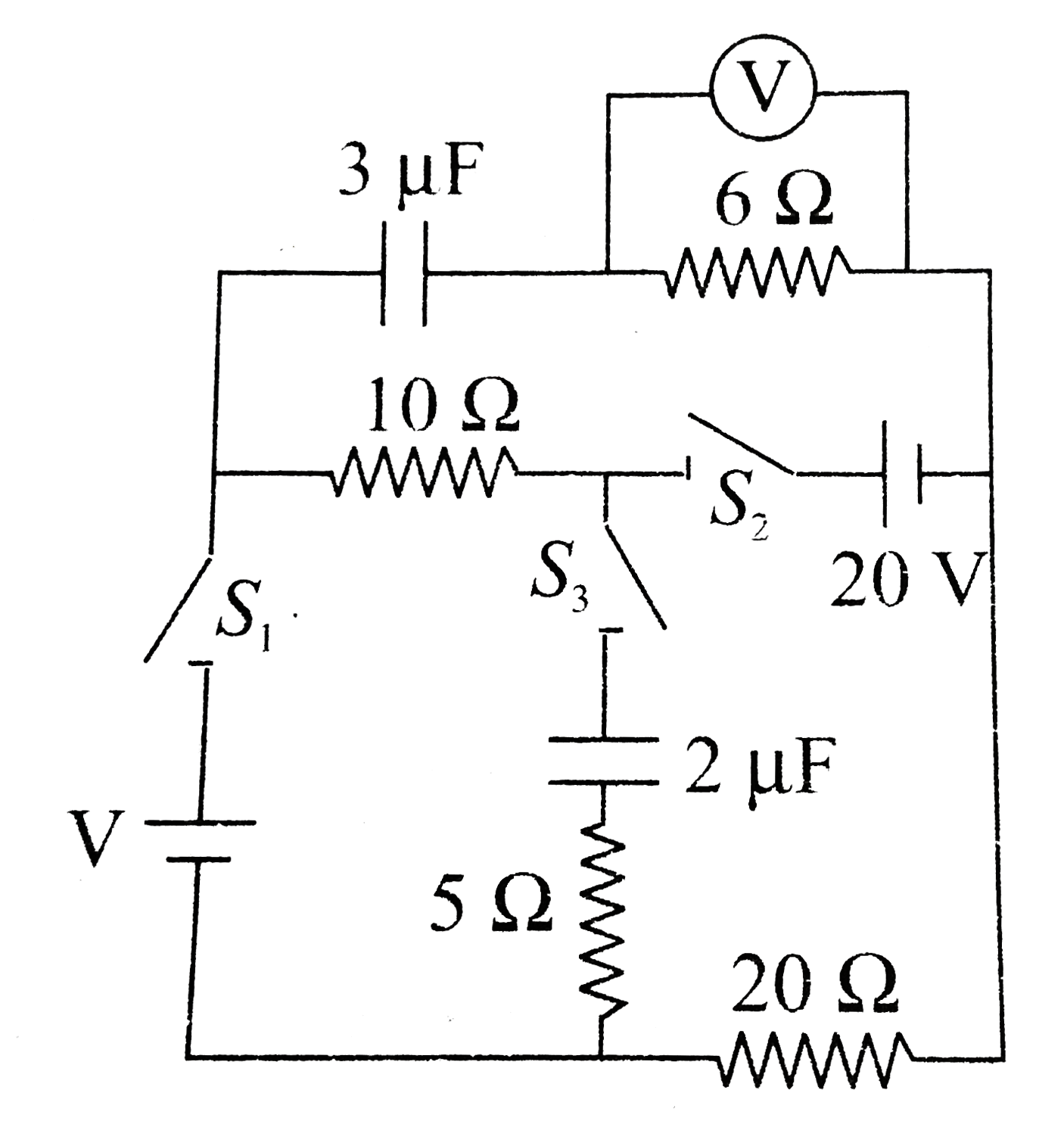
View SolutionOnly switch `S_1` closed in fig.
a. what is the steady-state reading of the voltmeter?
b. What is the charge on the `3muF` capacitor?
c. How much power does the 12V battery supply in the steady state after all the switches are closed?
d. What is the charge on `2muF` capacitor?
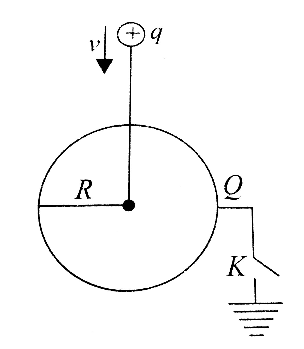
View SolutionA point charge `+q` is moved with a constant velocity v toward a solid conducting sphere carrying a charge Q. Find the (a) potential of th sphere, (b) charge induced as the function of r, (c ) charge flowing if we close the key K, and (d) current is the part (c ).
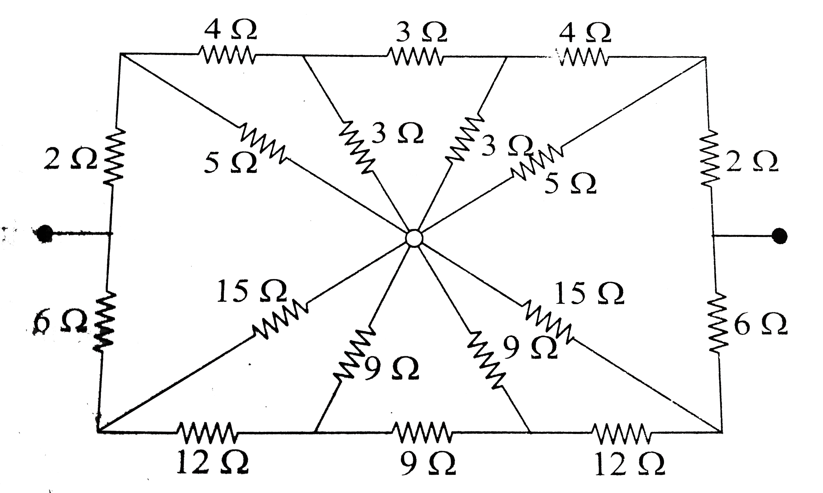
View SolutionCalculate equivalent resistance between A and B of the circuit shown in fig.
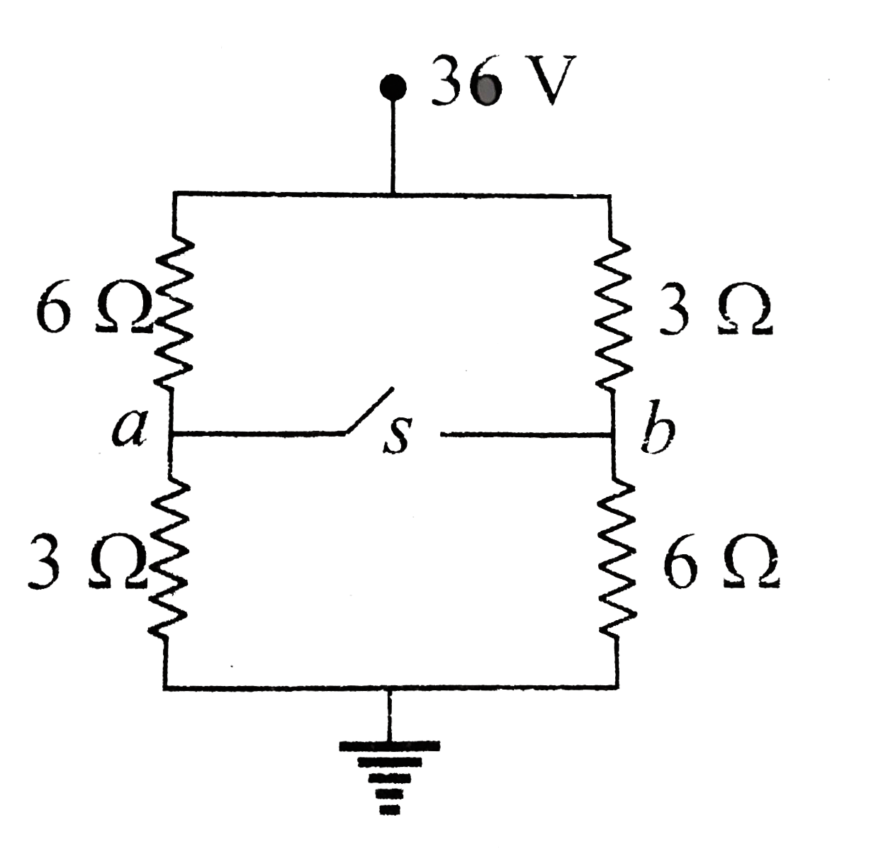
View SolutionIn the circuit shown in fig. calculate the following:
a. Potential differece between points a and b when switch S is open.
b.Current through S in the circuit
View Solution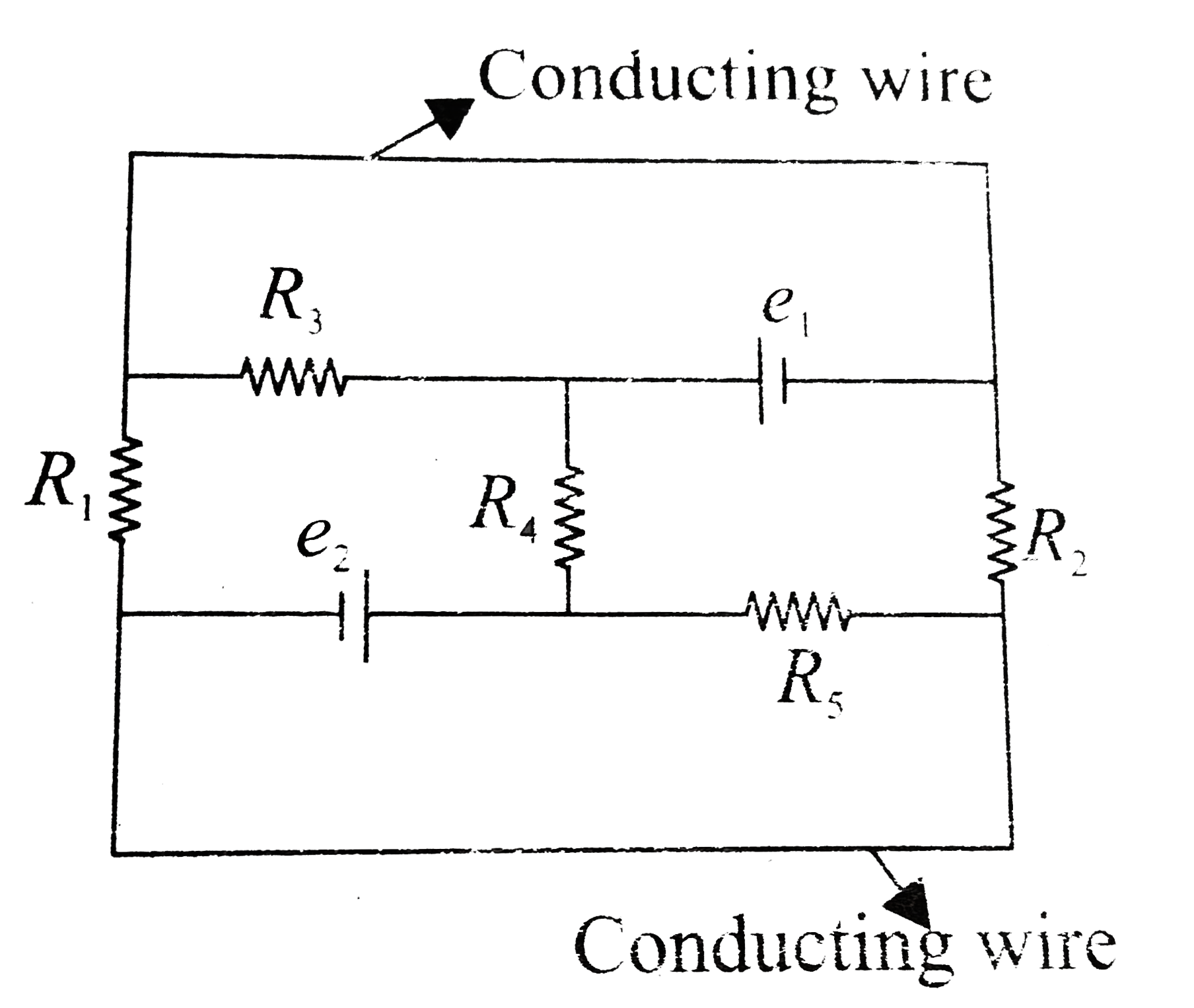
In the given cirucit, determine current through branch having indicated resistor `R_(4)` Given `R_(1) = R_(2) = 4Omega, R_(3) = R_(4) = 2Omega`
`R_(5) = 5Omega epsilon_(1) =5 V, epsilon _(2) =10V`
View SolutionDetermine current through batteries `epsilon_(1)` and `epsilon_(2)`
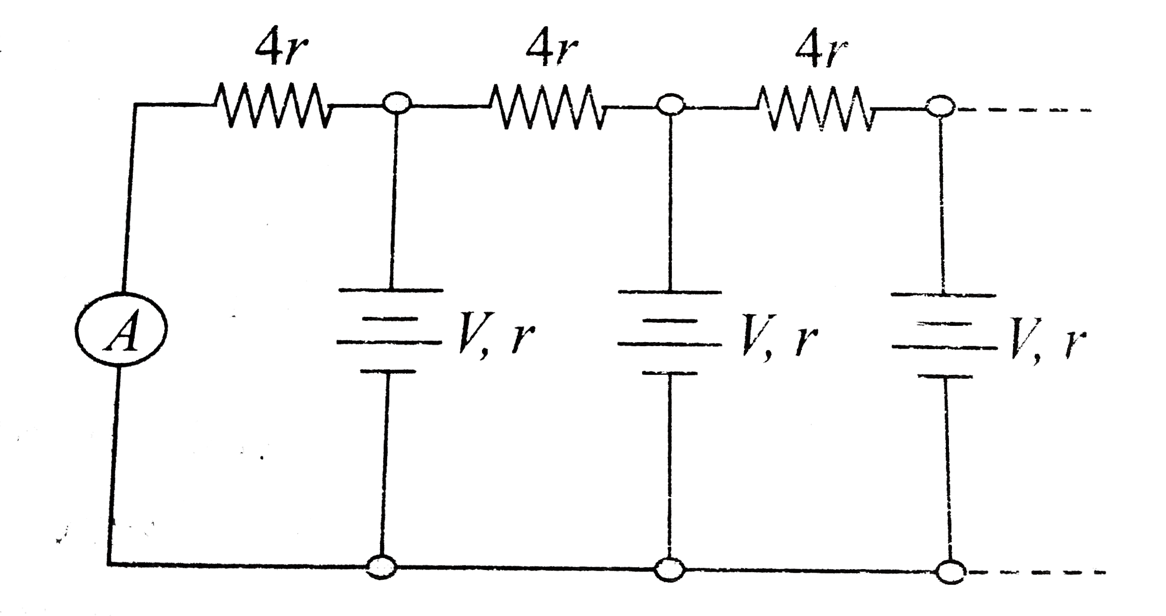
View SolutionThe cirucit shown in fig. extends to the right into infinity. Each battery has the electromotive force V(unknown) and the internal resistance r(known). Each resistor has the resistance 4r. The reading of the idal ammeter shown in the diagram is I. Find the value of V in terms of I and r.
View Solution
Subjective questions and complete solutions for chapter ELECTRIC CURRENT AND CIRCUIT of CENGAGE PHYSICS (ENGLISH) of Class 12