Complete Solutions to Exercise 4.1 of chapter INDUCTANCE of Class 12 book with complete answers and questions
| Class 12 | PHYSICS |
| Chapter | INDUCTANCE |
| CENGAGE PHYSICS | Exercise 4.1 |
| Number Of Questions | 24 |
| Academic Year | 2023-24 |
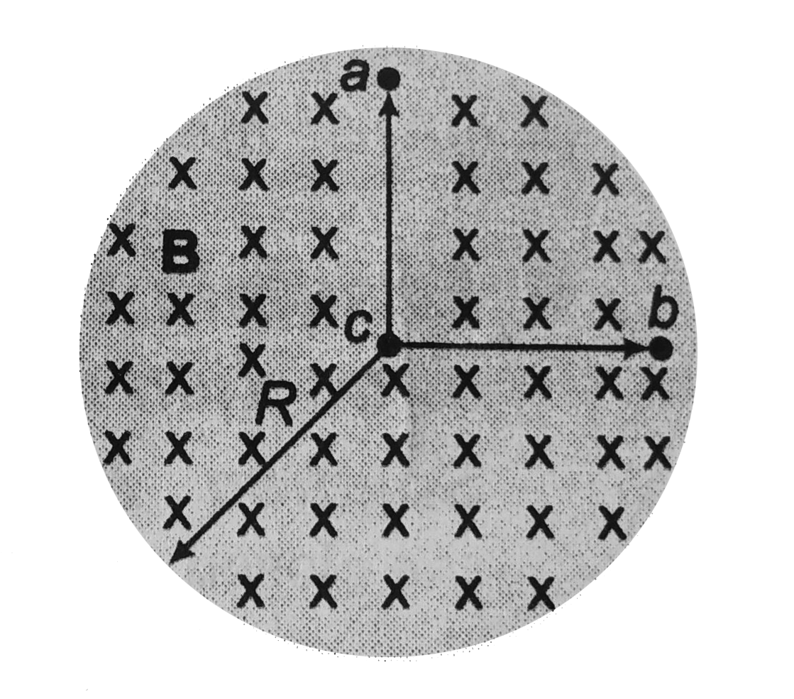
The magnetic field `B` at all points within `a` circular region of the radius `R` is uniform space and directed into the plane of the page in figure. If the magnetic field is increasing at a rate `dB//dt` what are the magnitude and direction of the force on as stationary positive point charge `q` located at points `a,b, c`? (Point a is a distance `r` above the centre of the region, point `b` is a distance `r` to the right to the centre and point `c` is at the centre of the region).
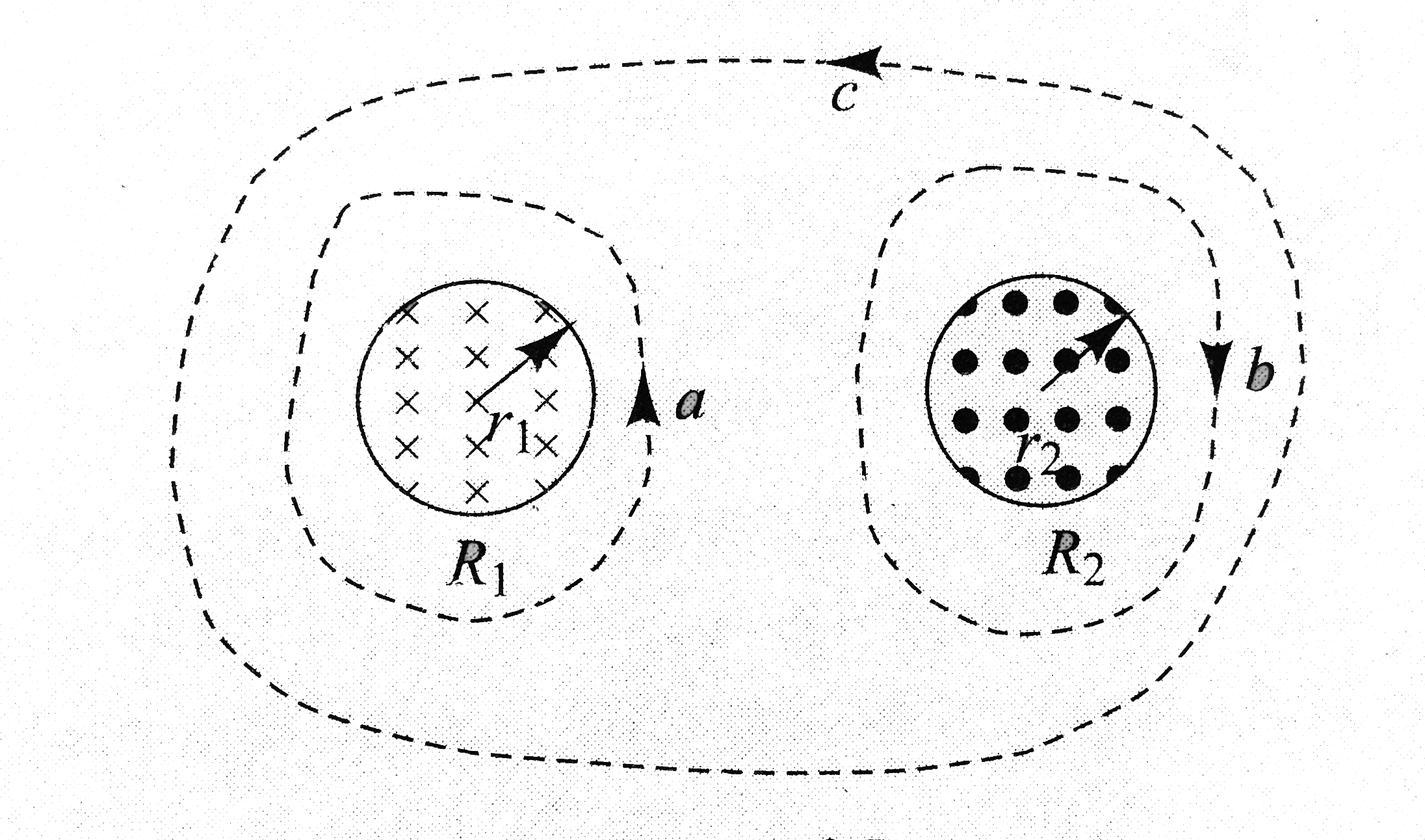
View SolutionFigure shows two circular regions `R_(1)` and `R_(2)` with redii `r_(1) = 21.2 cm` and `r_(2) = 32.3 cm`, respectively. In `R_(1)` there is a uniform magetic field `B_(1) = 48.6 mT` into the page and in `R_(2)` there is a uniform magnetic field `B_(2) = 77.2 mT` out of the page (ignore any fringing of these fields).Both fields are decreasing at the rate `8.50 mT s^(-1)`. Calculate the intergal `oint vec(E). vec(dl)` for each of the three identical paths.
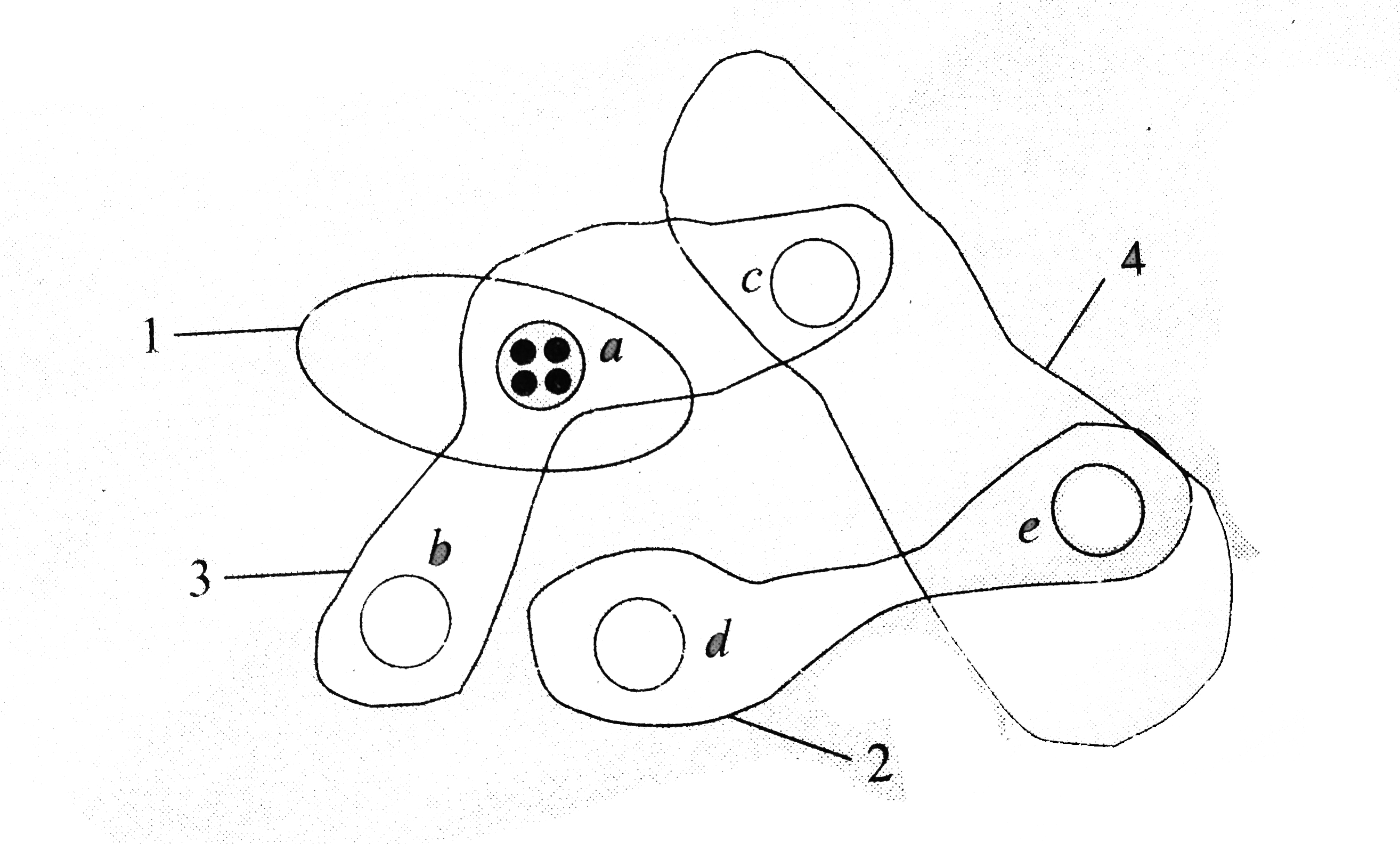
View SolutionFigure shows five lettered regions in which a uniform magnetic field extends directly either out of the page (as in region `a`) or into he page. The field is increasing in magnitude at the same steady rate in all five regions, the regions are identical in area. Also shows are four numbered paths along which `oint vec(E). vec(dl)` has the magnitudes given below in terms of a quantity mag. Determine whether the magnetic fields in regions `b` through `e` are directed into ot out of the page.
 ?
?
`|{:("Path",1,2,3,4),(oint vec(E).vec(dl),mag,2(mag),3(mag),0):}|`
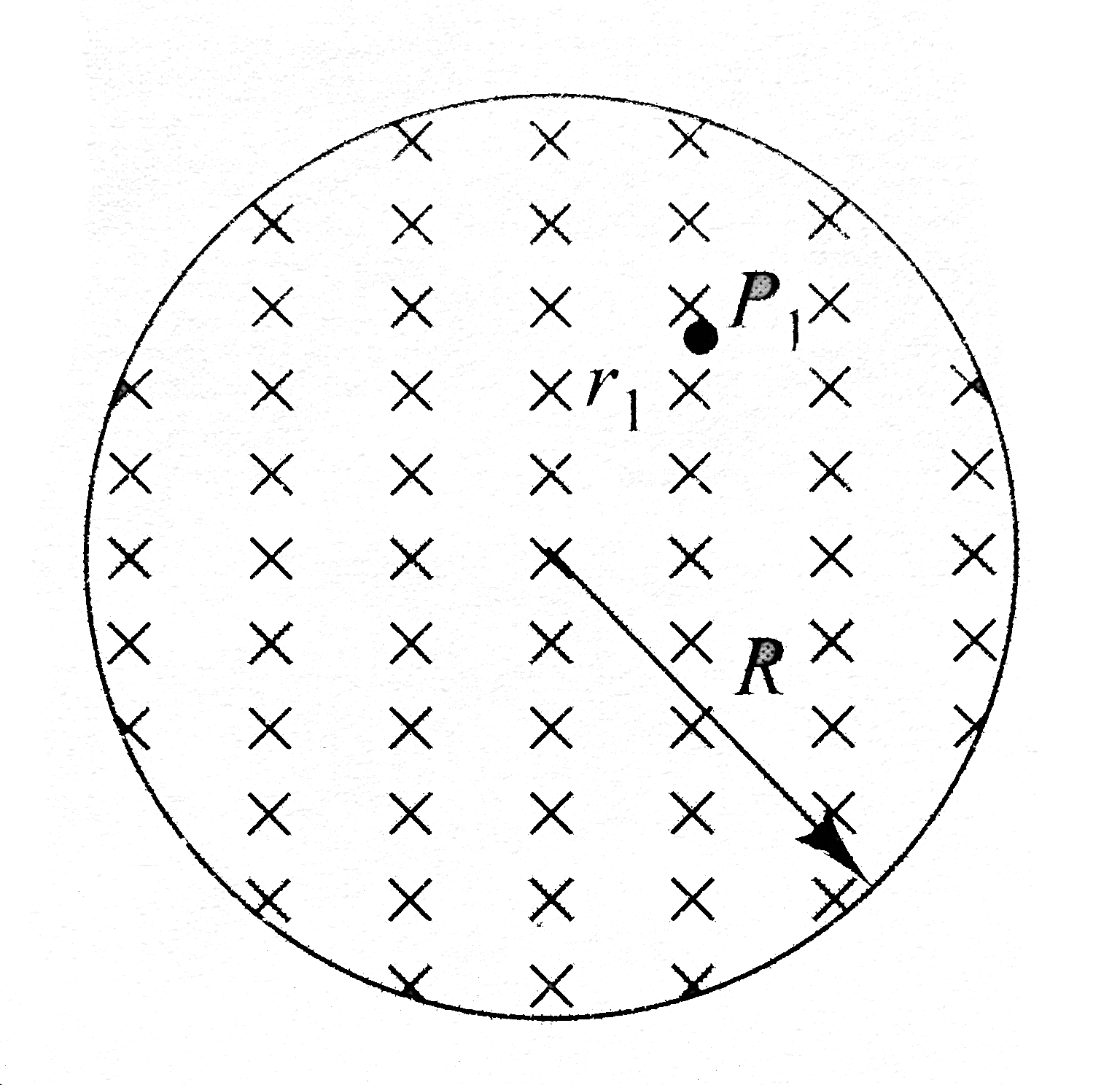
View SolutionA magentic field directed into the page changes with time according to `B = (0.0300t^(2) + 1.4.40)T`, where `t` is in seconds. The field has a circular cross section of radius `R = 2.50 cm`. What are the magitude and direction of the electric field at point `P_(1)` when `t = 3.00 s` and `r_(1) = 0.0200 m`?
View SolutionFigure shows an `LCR` circuit. When the switch is closed, the currents through resistor `R`, inductor `L`, and capacitor `C` are `I_(1),I_(2)`, and `I_(3)`, respectively. Determine the values of `I_(1),I_(2)`, and `I_(3)`.
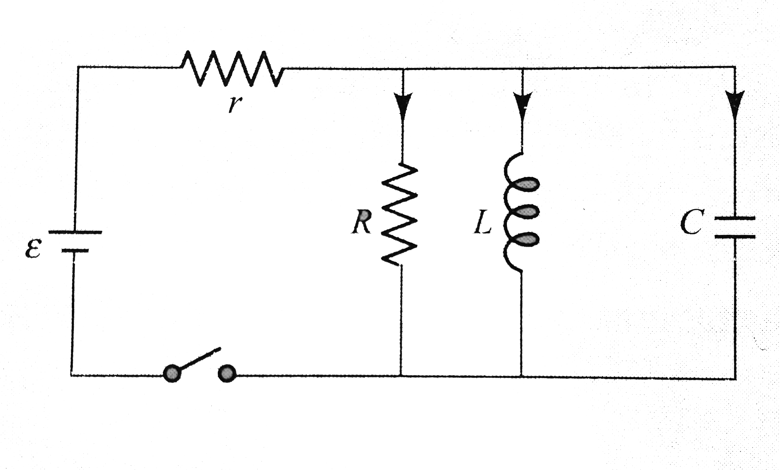
a. at `t = 0` b. at `t = oo`
View SolutionIt has been proposed to use large inductors as energy storage devices.
a. How much electrical energy is converted to light and thermal energy by a `200 - Omega` light bulb in one day?
b. If the amount of energy calculated in part (a) is stored in an inductor in which the current is `80.0 A`, what is the inductance?
View SolutionA `1 -k Omega` resistor is connected in series with a `10-mH` inductor, a `30 V` battery and an open switch. At time `t= 0`, the switch is suddenly closed.
a. What is the maximum current in this circuit and when does it occur?
b. What are the voltage drops across the inductor and across the resistor `20 mu s` after the switch is closed?
c. On a single set of axes, sketch the voltage across the resistor and the voltage across the inductor as functions of time. Also, sketch a graph of the current in the circuit as s function of time.
View SolutionA capacitor with capacitance `6 xx 10^(-5) F` is charged by connecting it to a `12 -V` battery. The capacitor is disconnected from the battery and connected across an inductor with `L = 1.50 H`.
a. What are the angular frequency `omega` of the electrical oscillations and the period of these oscillations (the time for one oscillation)?
b. What is the intial charge on the capacitor?
c. How much energy is intially stored in the capacitor?
d. What is the charge on the capacitor `0.0230` s after the connecting to the inductor is made? Interpret the sign of the your answer.
e. At the times given in part (d), what is the current in the inductor? Interpret the sign of your answer.
f. At the time given in part (d), how much electrical energy is stored in the capactior and how much is stored in the inductor?
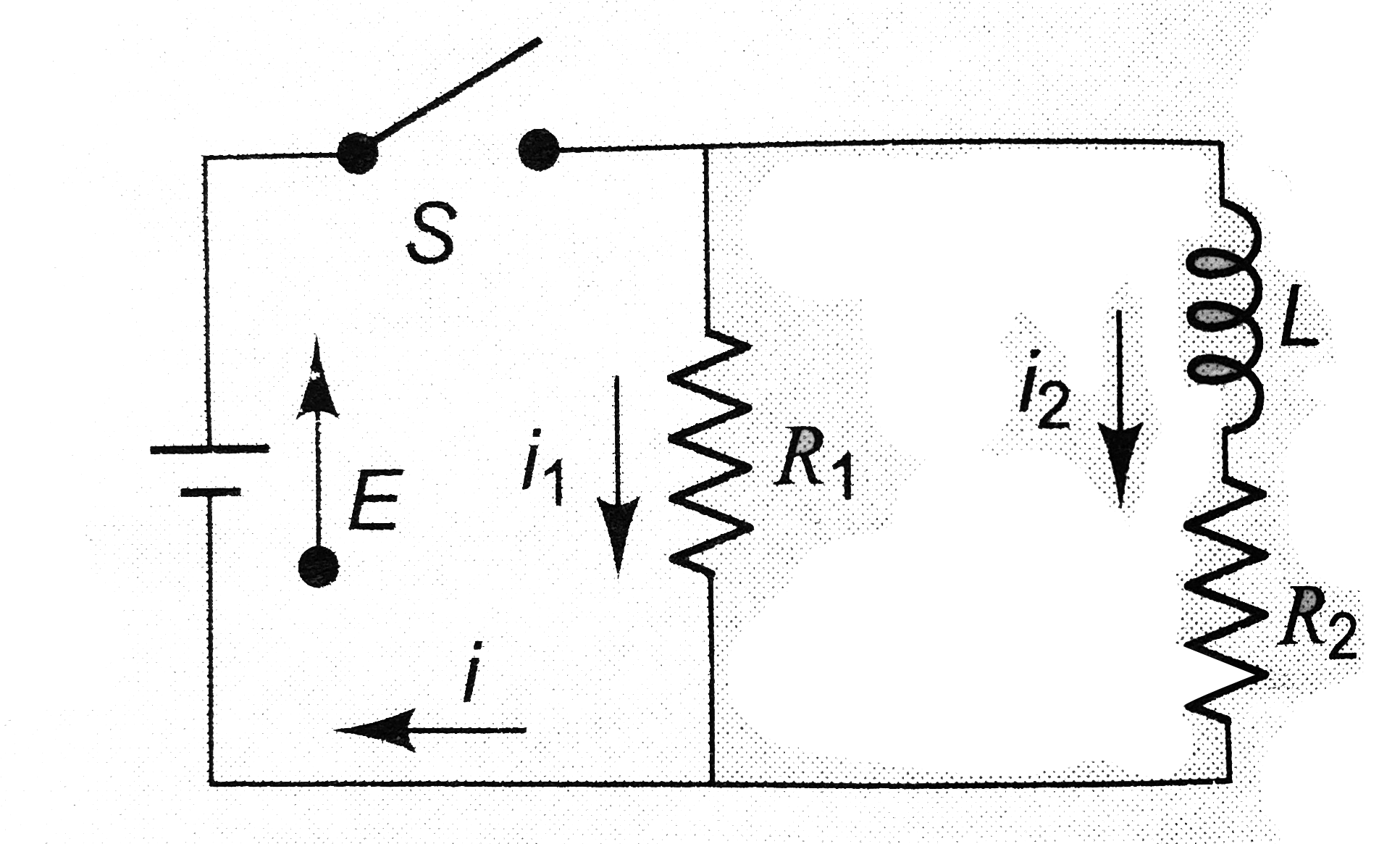
View SolutionIn the circuit shows in Fig. , `E = 10 V`, `R_(1) = 5 Omega`, `R_(2) = 10 Omega`, and `L = 5 H`. For the two separate conditions, (i) switch `S` is just closed and (ii) switch `S` is closed for a long time, calculate
a. current `i_(1)` through `R_(1)`,
b. current `i_(2)` through `R_(2)`,
c. current `i` through the switchs,
d. the potential difference across `R_(2)`,
e. the potential difference across `L`,
f. `di_(2)//dt`.
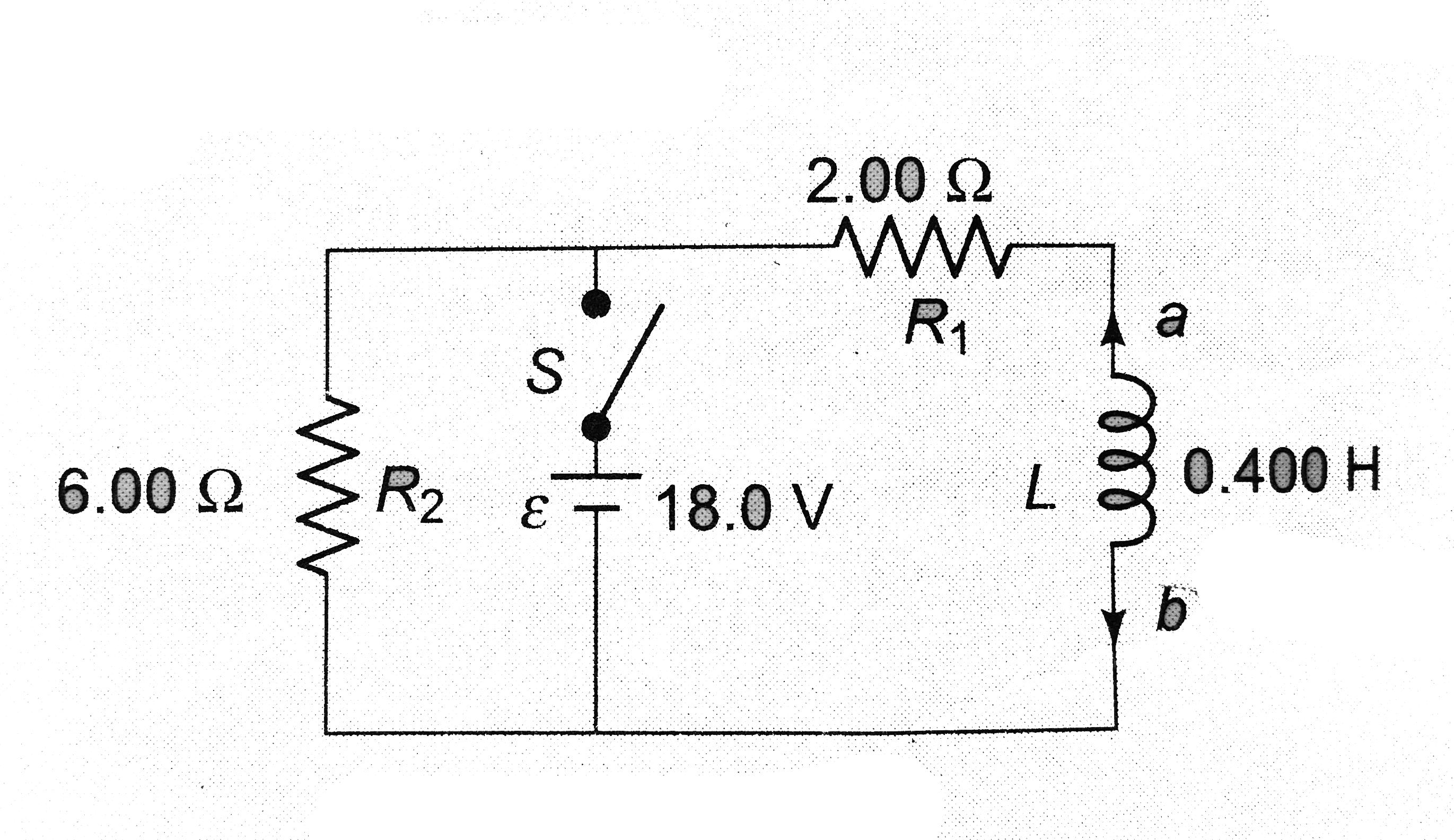
View SolutionIn Fig. the switch is closed and steady-state conditions are established. The switch is thrown open at `t = 0`.
a. Find the initial voltage `E_(0)` across `L` just after `t = 0`. Which end of the coil is at the heigher potential : `a` or `b`?
b. Make freehand graphs of the current in `R_(1)` and `R_(2)` as a funtion of time, treating the steady-state directions as positive. Show values before and after `t = 0`.
c. How long after `t = 0` does the current in `R_(2)` have the value `2 mA`?
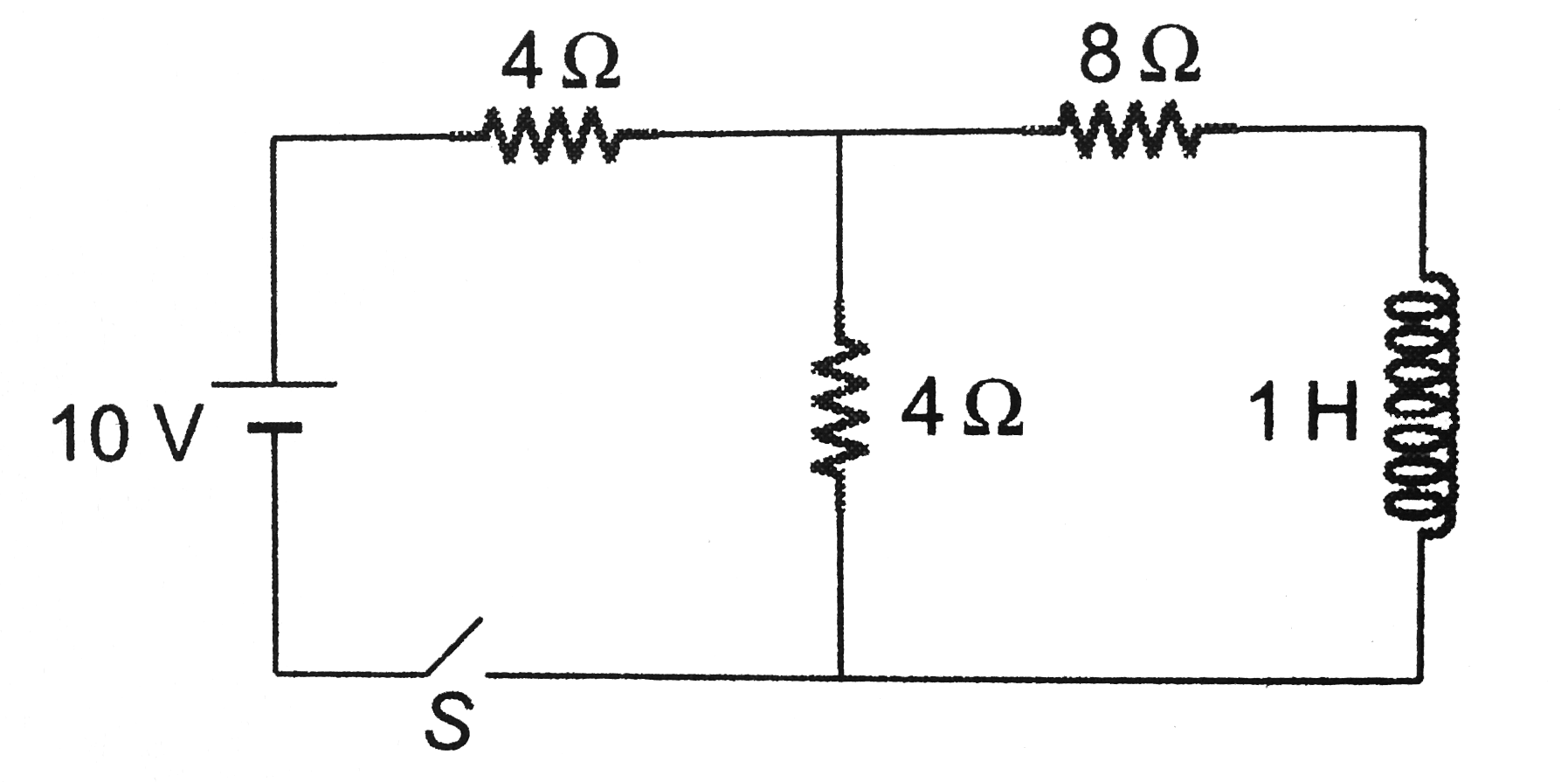
View SolutionThe switch in figure is closed at time `t = 0`. Find the current in the inductor and the current through the switch as functions of time thereafter.
View Solution`AB` is a part of circuit. Find the potential difference `V_(A) - V_(B)` if
a. current `I = 2 A` and is constant,
b. current `i = 2 A` and is increasing at the rate of `1 A s^(-1)`,
c. current `i = 2 A` and is decreasing at the rate `1 A s^(-1)`,

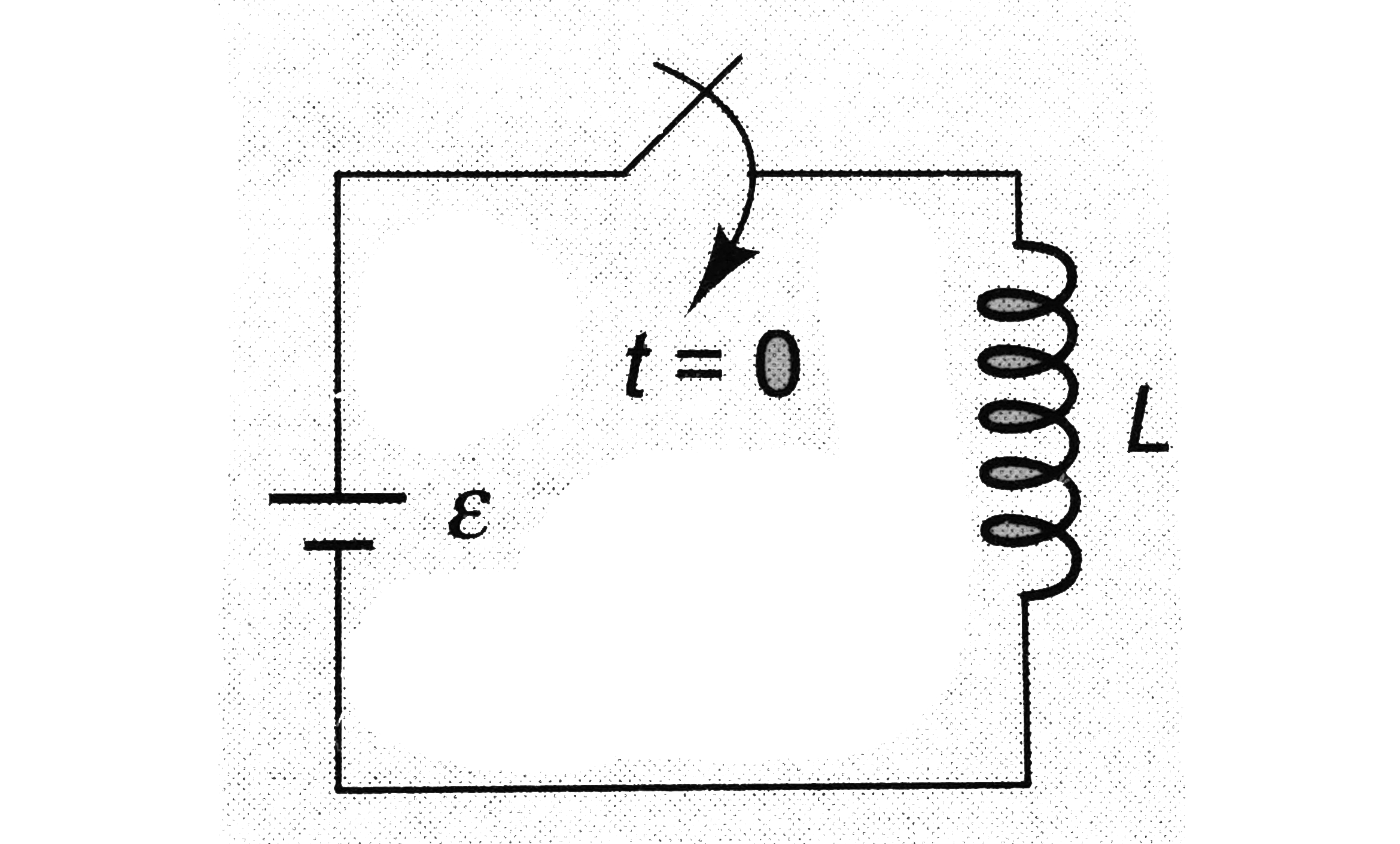
View SolutionA circuit contains an ideal cell and an inductor with a switch. Initially, the switch is open. It is closed at `t = 0`. Find the current as a function of time.
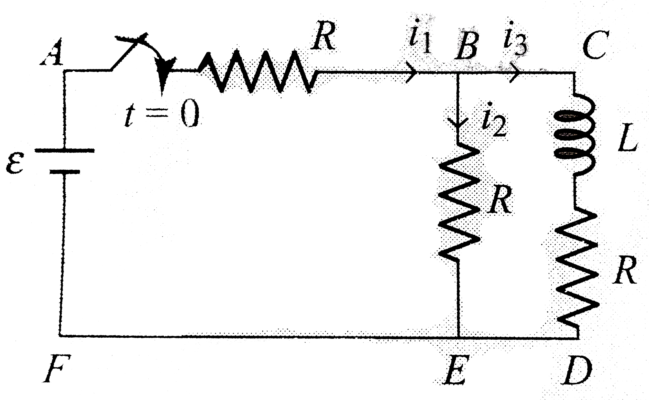
View SolutionIn the following circuit (Fig.) the switch is closed at `t = 0`. Find the current `i_(1),i_(2),i_(3)` and `di_(3)//dt` at `t = 0` and at `t = oo`. Intitially, all current are zero.
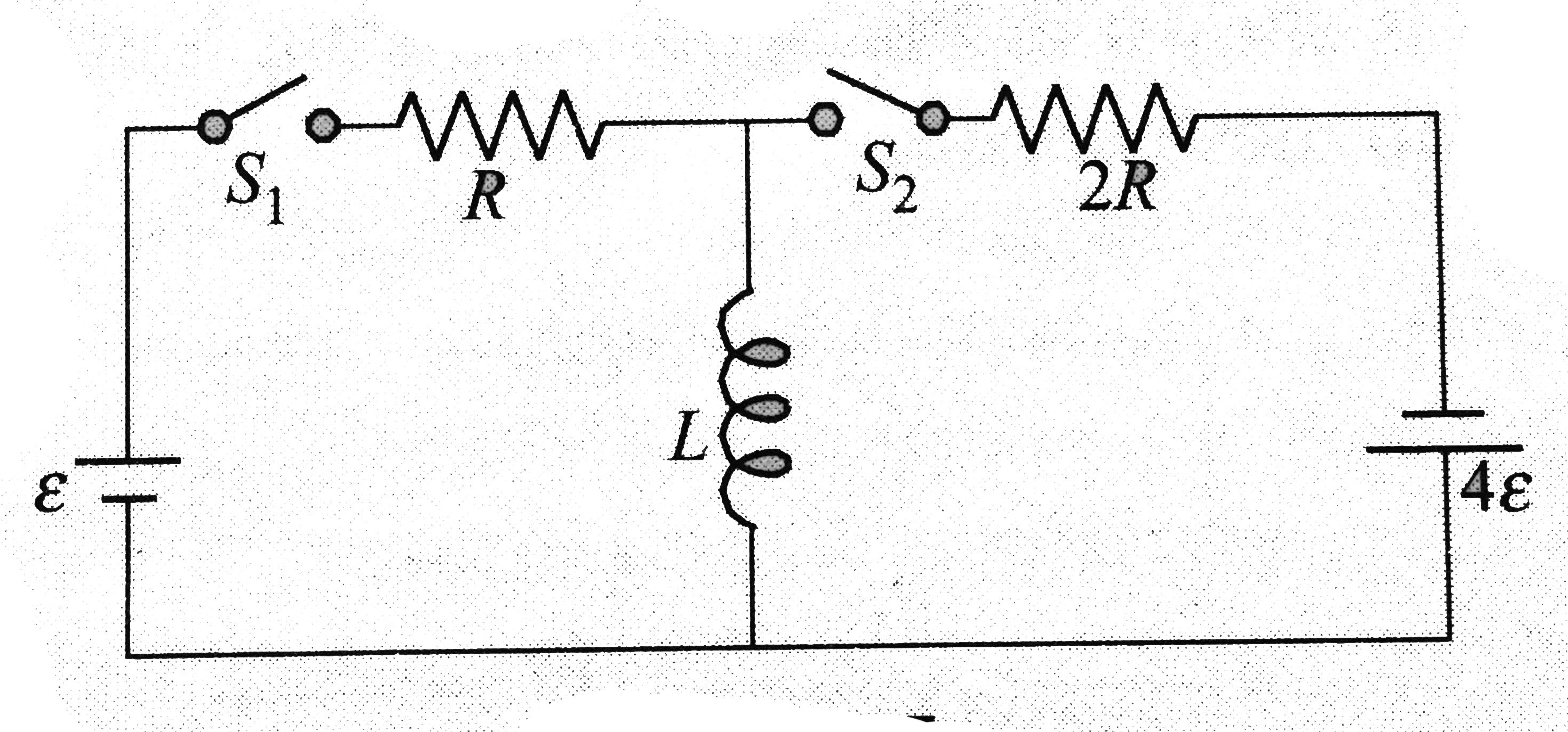
View SolutionIn a circuit `S_(1)` remains closed for a long time and `S_(2)` remain open. Now `S_(2)` is closed and `S_(1)` is opened. Find out the `di//dt` in the right loop just after the moment.
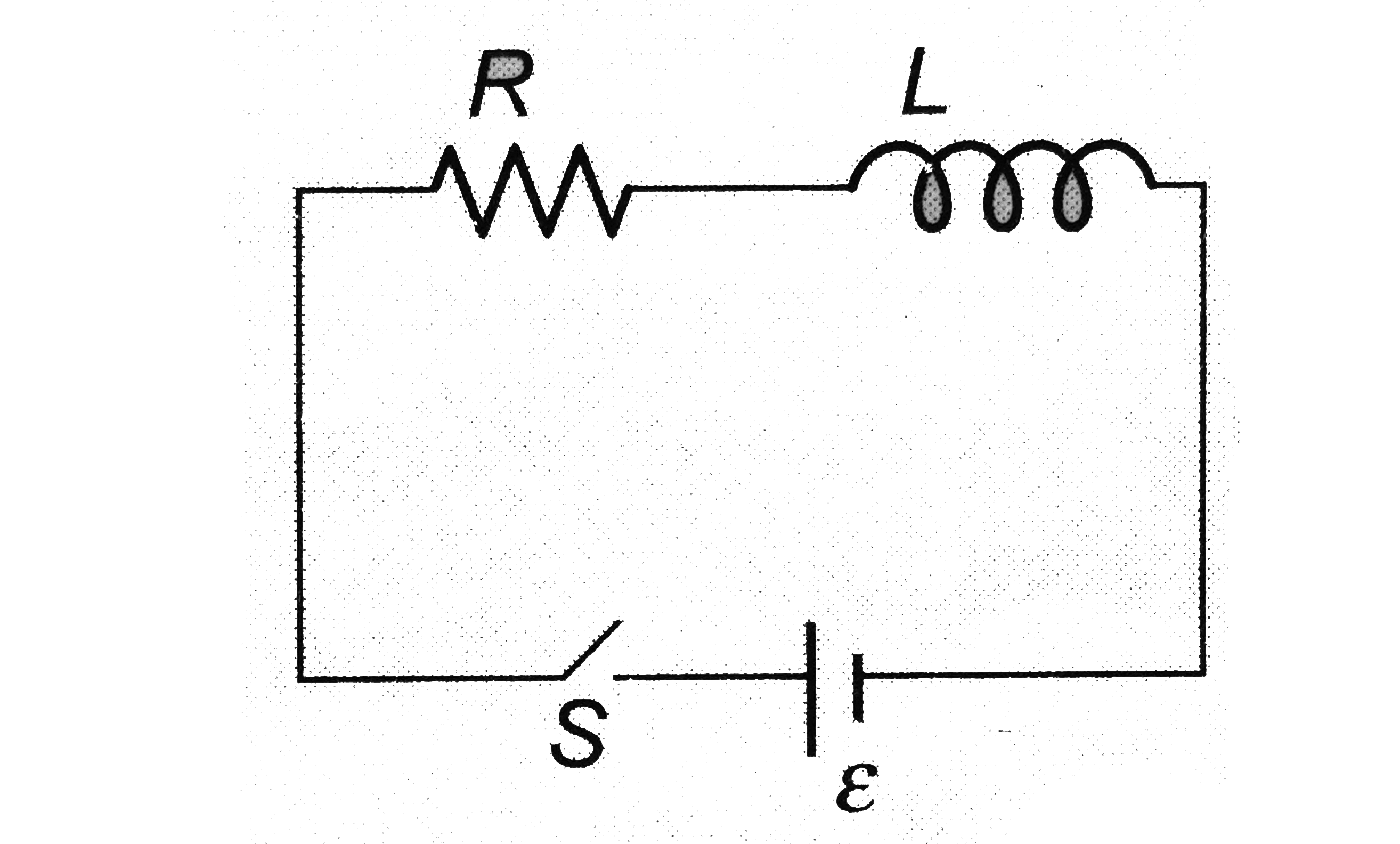
View SolutionAt `t = 0`, switch `S` is closed (shown in Fig.). After a long time, suddenly the inductance of the inductor is made `eta` times lesser `(L//eta)` than its initial value. Find out current just after the operation.
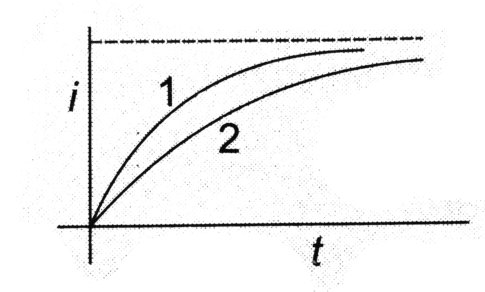
View SolutionWhich of the two curves shows has lesser time constant.
View SolutionTwo insulated wires are wound on the same hollow cylinder, s as to from two solenoids shering a common air-filled core. Let `l` be the length of the core, A the cross -sectional area of the core, `N_(1)` the number of times the first wire is wound around the core, and `N_(2)` the number of times the second wire is wound around the core. Find the mutual inductance of the two solenoids, neglecting the end effects.
View SolutionFind the mutual inductance of two concentric coils of radii `a_(1)` and `a_(2)(a_(1) lt lt a_(2))` if the planes of the coils are same.
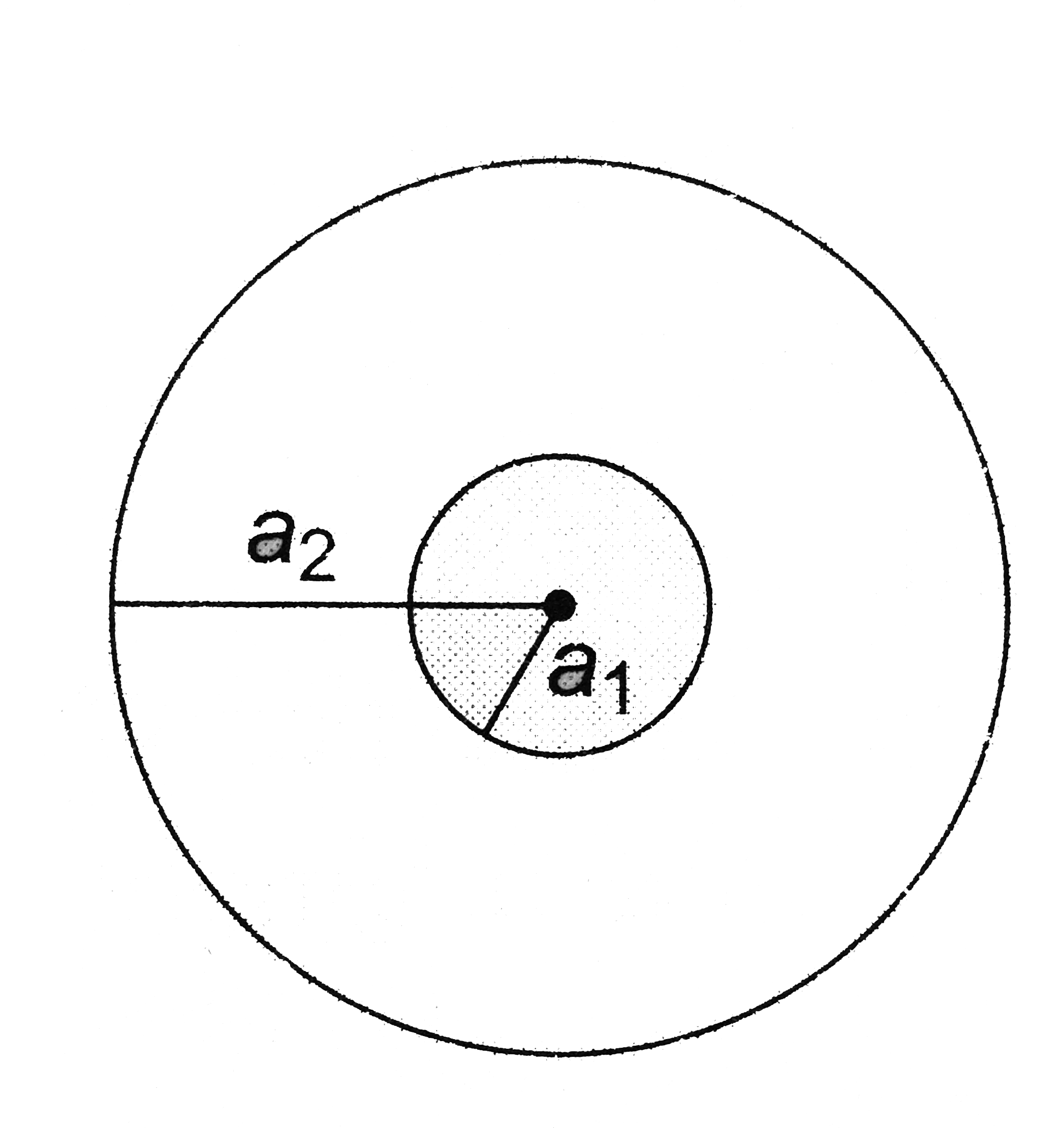
View SolutionSolve problem `19` if the planes of the coils are perpendicular.
View SolutionSolve problem `19` if the planes of the coils make an angle `theta` with each other.
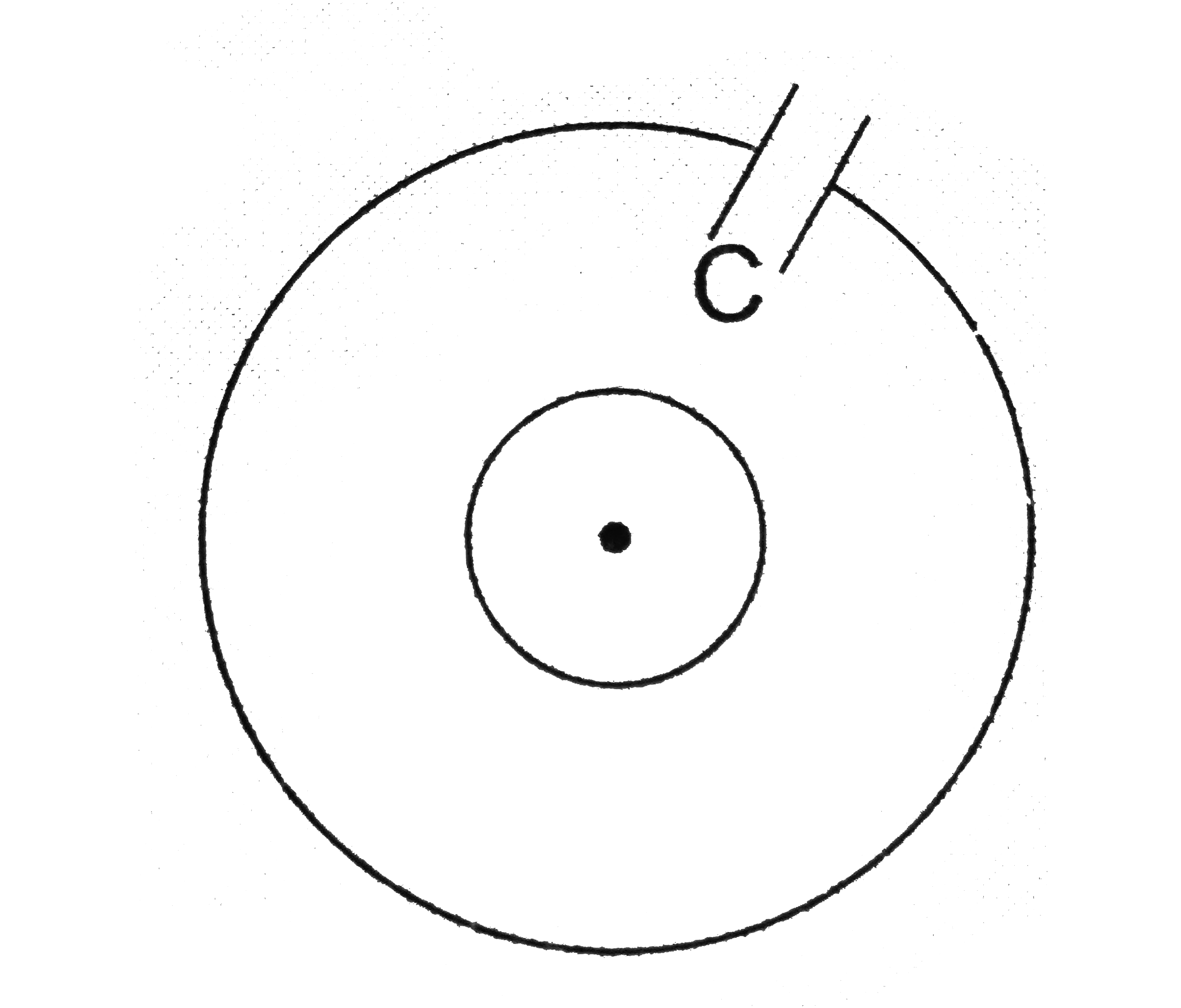
View SolutionFigure. shows two concentric coplanar coils with radii `a` and `b(alt ltb)`. A current `I = 2t` flows in the smaller loop. Neglecting self-inductance of the larger loop,
a. find the mutual inductance of the two coils,
b. find the emf induced in the larger coil,
c. if the resistance of the larger loop is `R`, find the current in it as a function of time.

View SolutionIf a capacitor of capacitance `C` is also connected in the larger loop as shows in Fig . , find the charge on the capactior as a function of time.
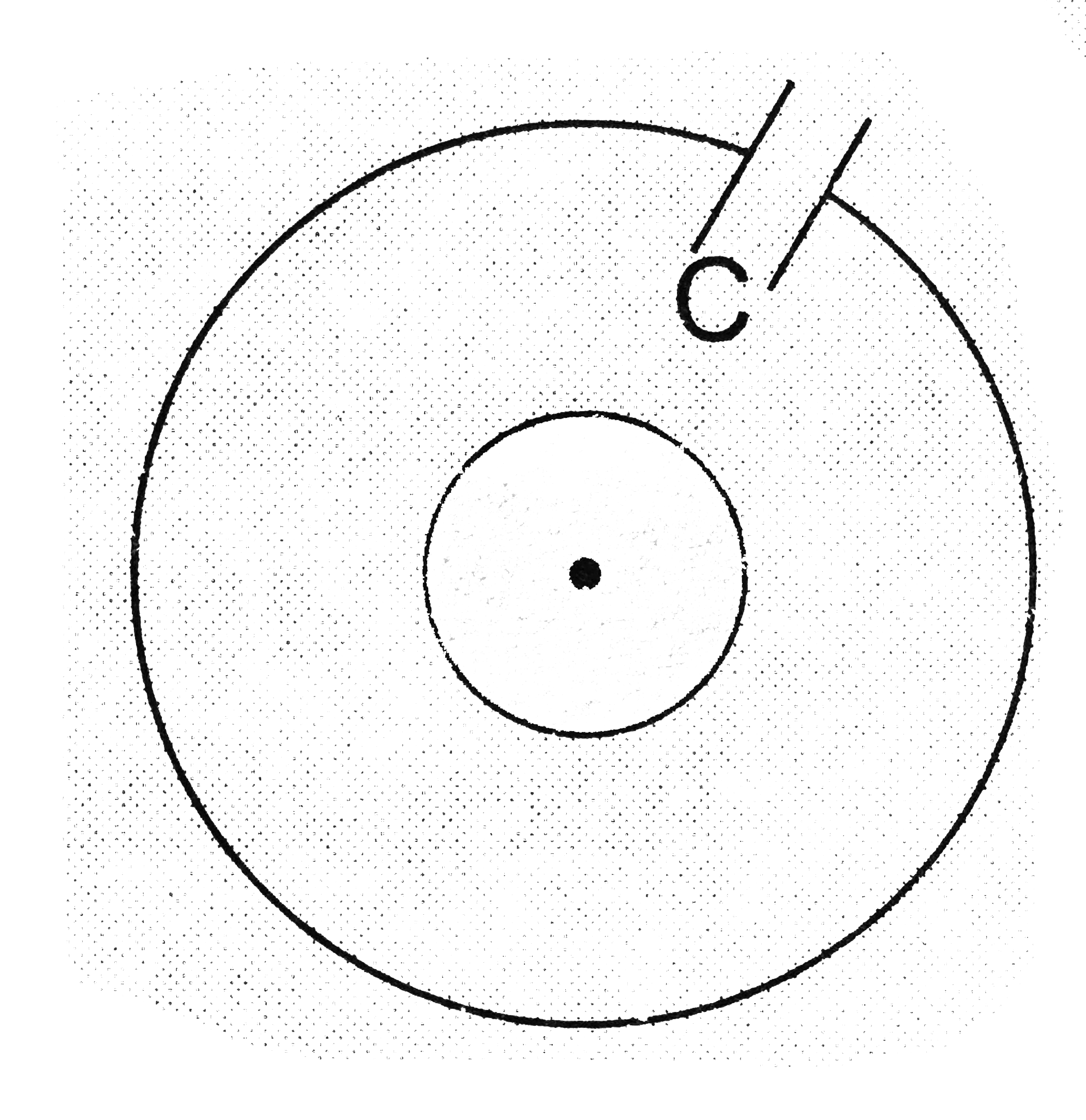
View SolutionIf the current in the inner loop changes according to `I = 2t^(2)` (Fig .), then find the current in the capacitor as a function of time.
View Solution
Exercise 4.1 questions and complete solutions for chapter INDUCTANCE of CENGAGE PHYSICS (HINGLISH) of Class 12
All Exercises from CENGAGE PHYSICS Class 12 PHYSICS INDUCTANCE
- Archives (fills In The Blanks)
- Archives (integer)
- Archives (linked Compreshension)
- Archives (multiple Correct)
- Archives (single Correct )
- Comprehension Type
- Concept Based
- Exercise 4.1
- Exercises (assertion-reasoning)
- Exercises (integer)
- Exercises (linked Compreshension)
- Exercises (multiple Correct )
- Exercises (single Correct )
- Exercises (subjective)
- Illustration
- Multiple Correct Answer
- Single correct Answer Type
- Solved Examples
- Subective Type