Complete Solutions to Exercises (single Correct ) of chapter INDUCTANCE of Class 12 book with complete answers and questions
| Class 12 | PHYSICS |
| Chapter | INDUCTANCE |
| CENGAGE PHYSICS | Exercises (single Correct ) |
| Number Of Questions | 65 |
| Academic Year | 2023-24 |
A mutual inductor consists of two coils `X` and `Y` as shown in Fig. in which one-quarter of the magnetic flux produced by `X` links with `Y`, giving a mutual inductance `M`. What will be the mutual inductance when `Y` is used as the primary?

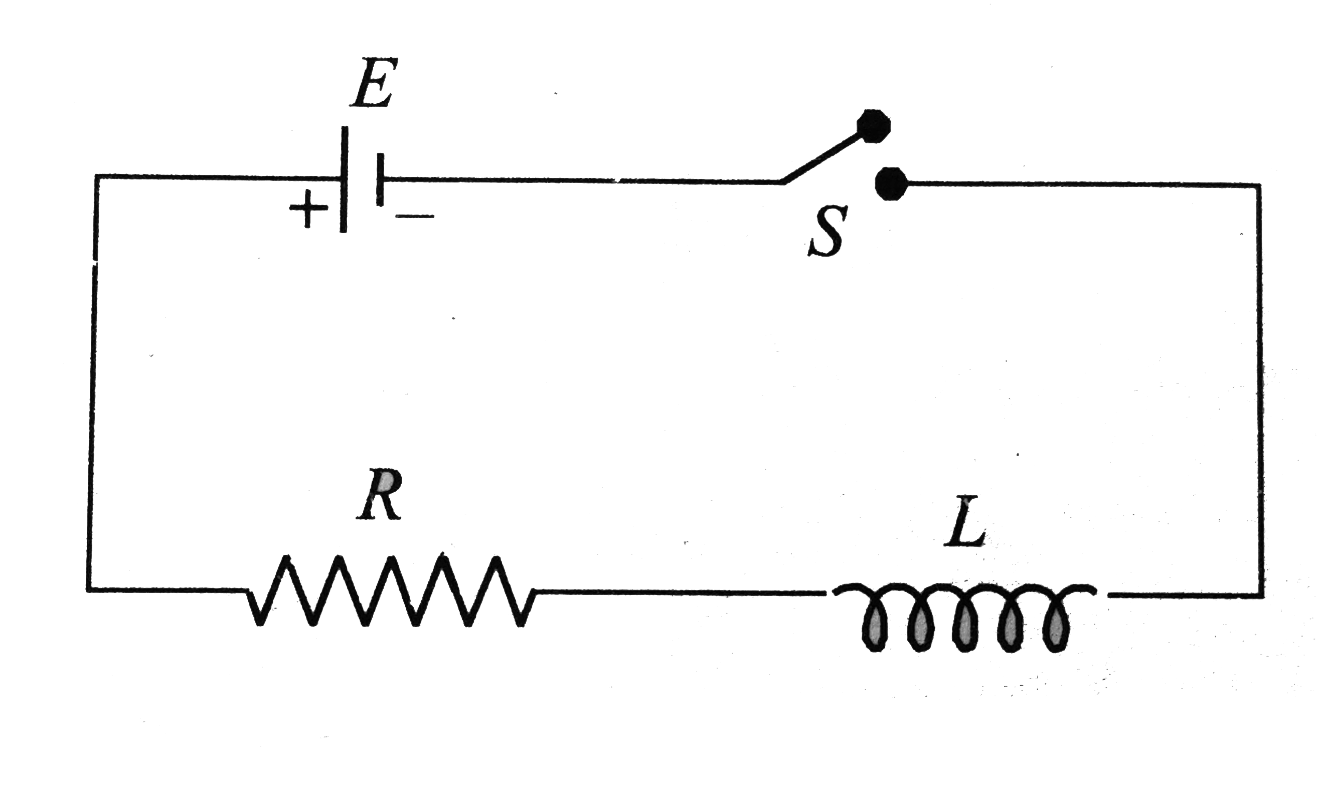
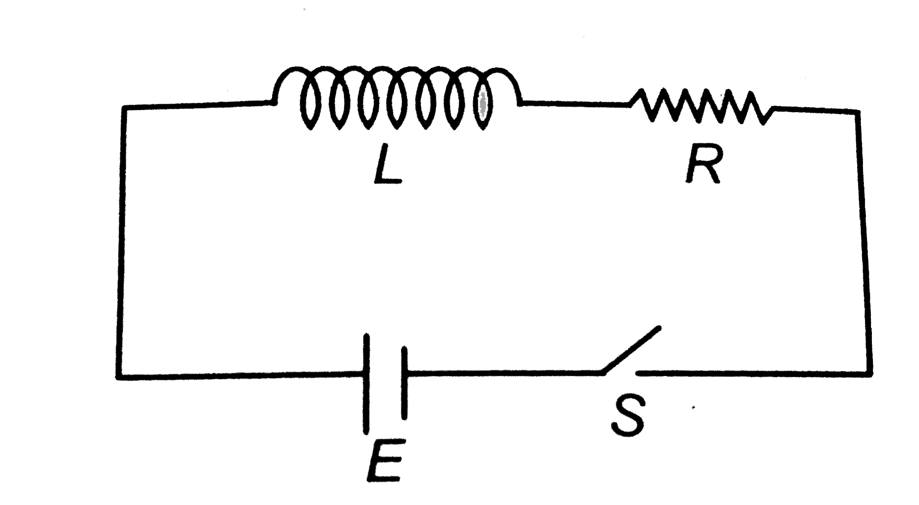
View SolutionSwitch `S` of the circuit shows in Fig. is closed at `t = 0`. If `e` denotes the induced emf in `L` and `i` the current flowing through the circuit at time `t`, then which of the following graphs correctly represents the variation of `e` with `i`?
View SolutionA small coil of radius `r` is placed at the centre of a large coil of radius `R`, where `R gtgt r`. The two coils are coplanar. The mutual inductance between the coils is proportional to
View SolutionA circuit contains two inductors of self-inductance `L_(1)` and `L_(2)` in series (Fig) If `M` is the mutual inductence, then the effective inductance of the circuit shows will be

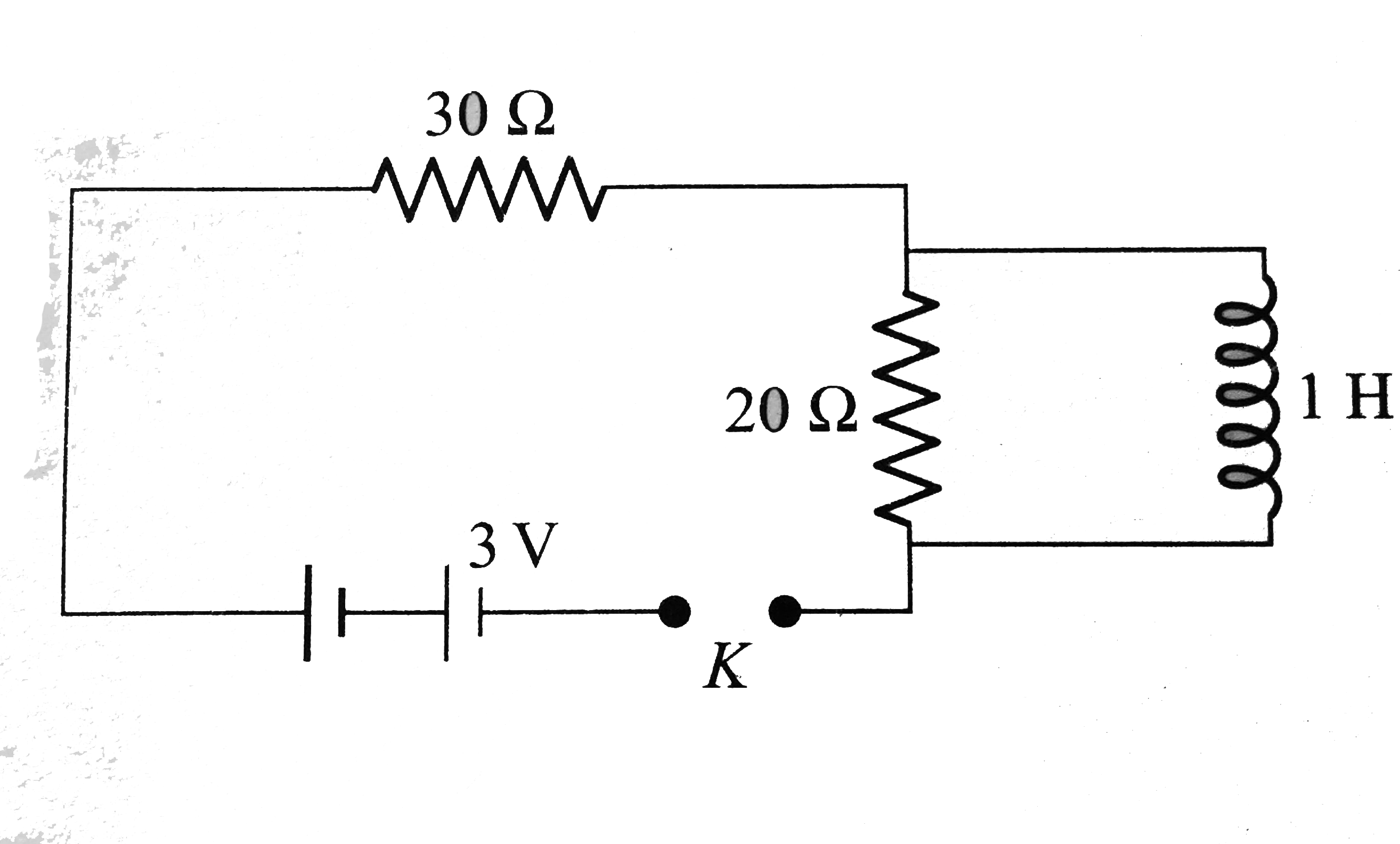
View SolutionIn the circuit Fig the final current through `30 Omega` resistance when circuit is completed is
View SolutionThe coefficient of mutual inductance of two circuits `A` and `B` is `3 mH` and their respective resistanaces are `10` and `4 Omega`. How much current should change in `0.02 s` in circuit `A`, so that the induced current in `B` should be `0.0060 A`?
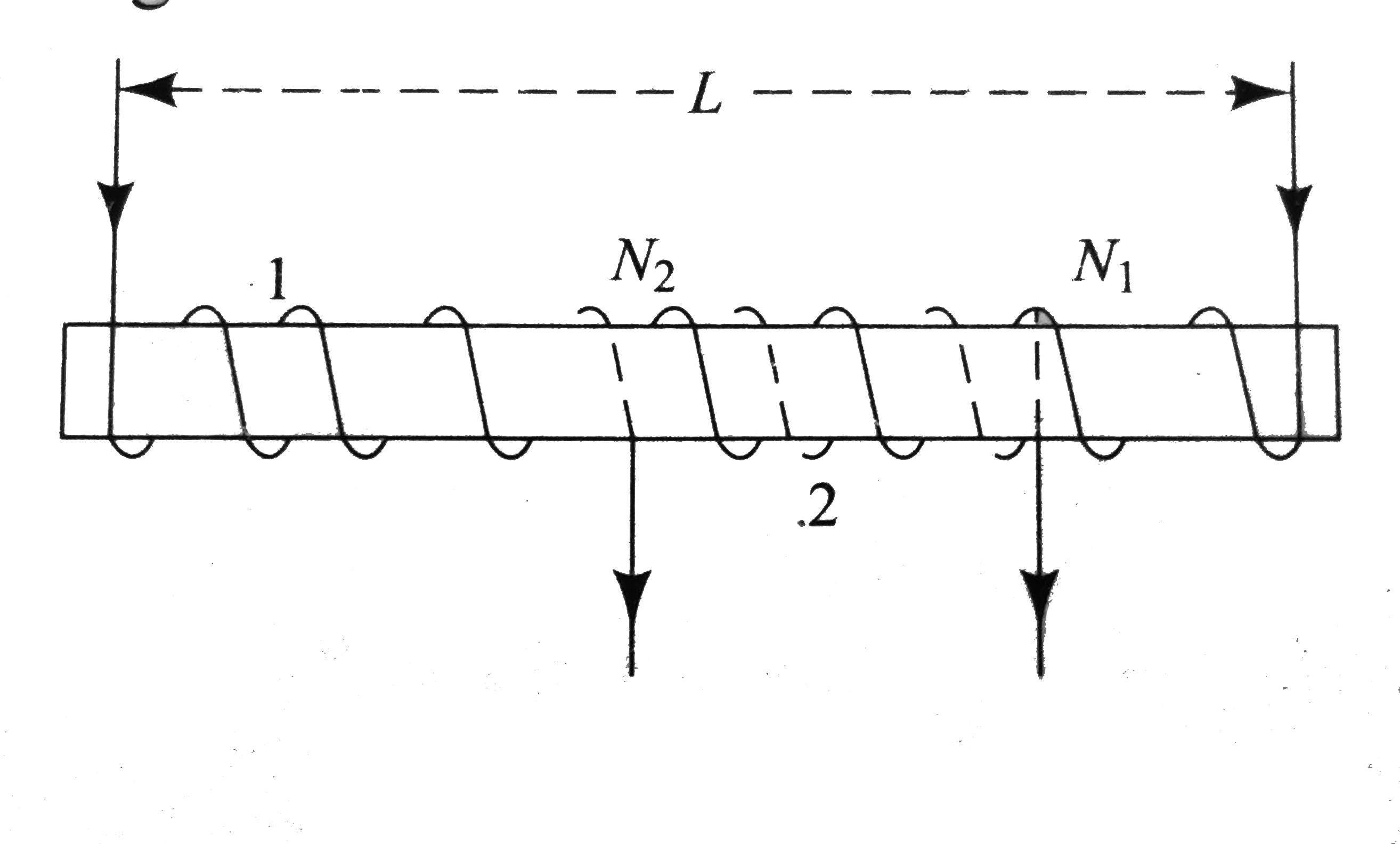
View SolutionA long solenoid of length `L`, cross section `A` having `N_(1)` turns has about its center a small coil of `N_(2)` turns as shows in Fig The mutual inductance of two circuits is
View SolutionAn emf of `15 V` is applied in a circuit containing `5 H` indutance and `10 Omega` resistance. The ratio of the currents at time `t = oo` and `t = 1 s` is
View SolutionIn Fig (a) and (b), two air-cored solenoids `P` and `Q` have been shows. They are placed near each other. In Fig (a), when `I_(P)`, the current in `P`, changes at the rate of `5 A s^(-1)`, an emf of `2 mV` is induced in `Q`. The current in `P` is then switched off, and the current changing at `2 A s^(-1)` is fed through `Q` as shows in the figure. What emf will be induced in `P`?


View SolutionA coil of inductance `0.20 H` is connected in series with a switch and a cell of emf `1.6 V`. The total resistance of the circuit is `4.0 Omega`. What is the initial rate of growth of the current when the switch is closed?
View SolutionThe length of a wire required to manufacture a solenoid of length `l` and self-induction `L` is (cross-sectional area is negligible)`
View SolutionThe inductance `L` of a solenoid of length `l`, whose windings are made of material of density `D` and resistivity `rho`, is (the winding resistance is`R`)
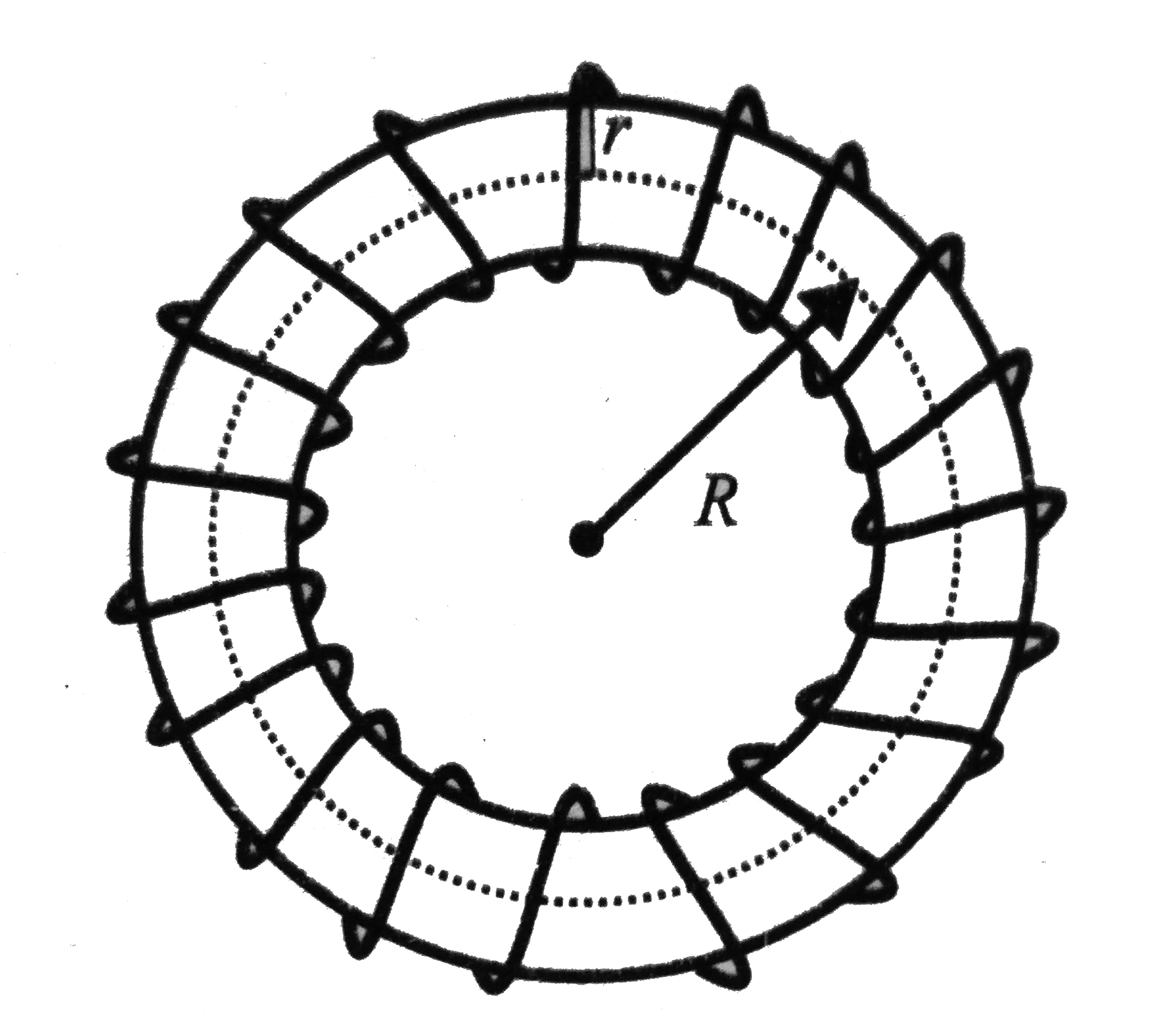
View SolutionA toroid is wound over a circular core. Radius of each turn is `r` and radius of toroid is `R (gt gt r)`. The coefficient of self-inductance of the toroid is given by
View SolutionA straight solenoid of length `1 m` has `5000` turns in the primary and `200` turns in the secondary. If the area of cross section is `4 cm^(2)`, the mutual inductance will be
View SolutionThe approximate formula expressing the formula of mutual inductance of two coaxial loops of the same redius `a` when their centers are separated by a distance `l` with `l gt gt a` is
View SolutionThe length of a thin wire required to manufacture a solenoid of length`l = 100 cm` and inductance `L = 1 mH`, if the solenoid's cross-sectional diameter is considerably less than its length is
View SolutionCurrent in a coil of self-inductance `2.0 H` is increasing as `I = 2 sin t^(2)`. The amount of energy spent during the period when the current changes from `0` to `2 A` is
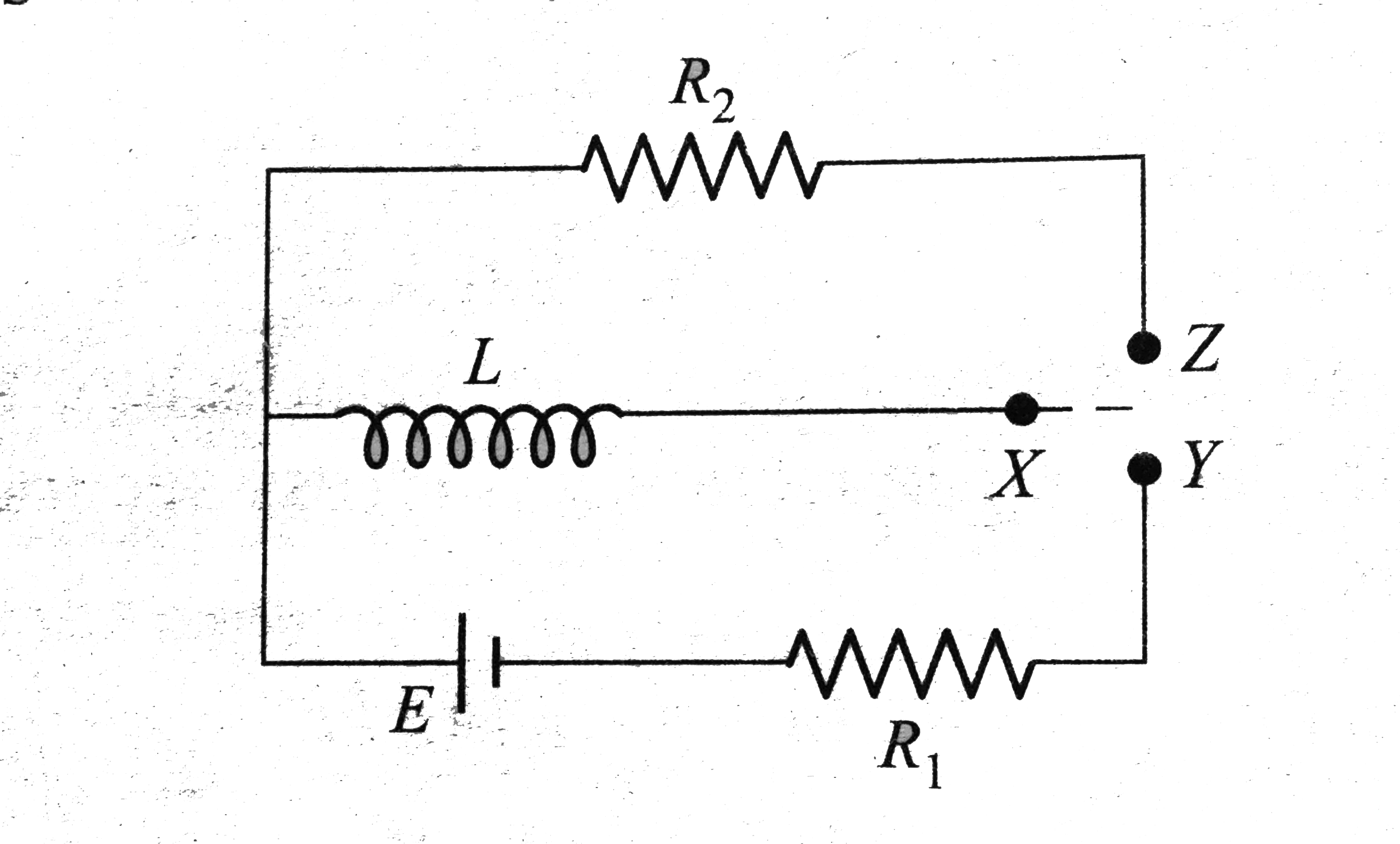
View SolutionIn the current shows Fig `x` is joined to `Y` for a long time and then `X` is joined to `Z`. The total heat produced in `R_(2)` is
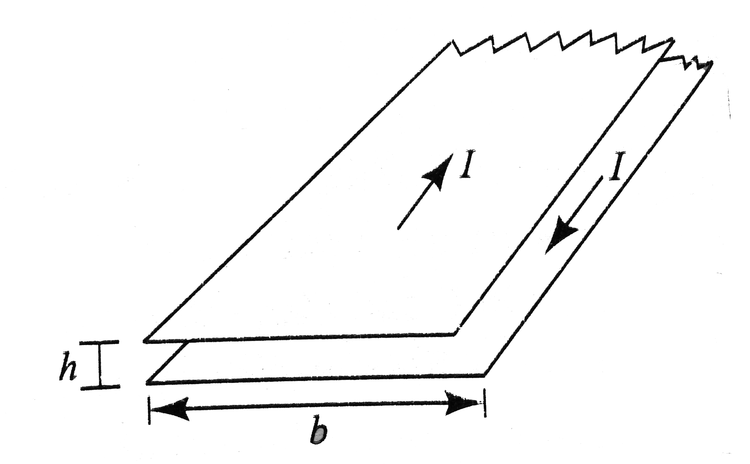
View SolutionCalculate the inductance of a unit length of a double tape line as shows in Fig if the tapes are separated by a distance `h` which is considerably less than their width `b`.
View SolutionFind the inductance of a unit length of two parallel wires, each of radius a, whose centers are a distance d apart and carry equal currents in opposite direction. Neglect the flux within the wire.
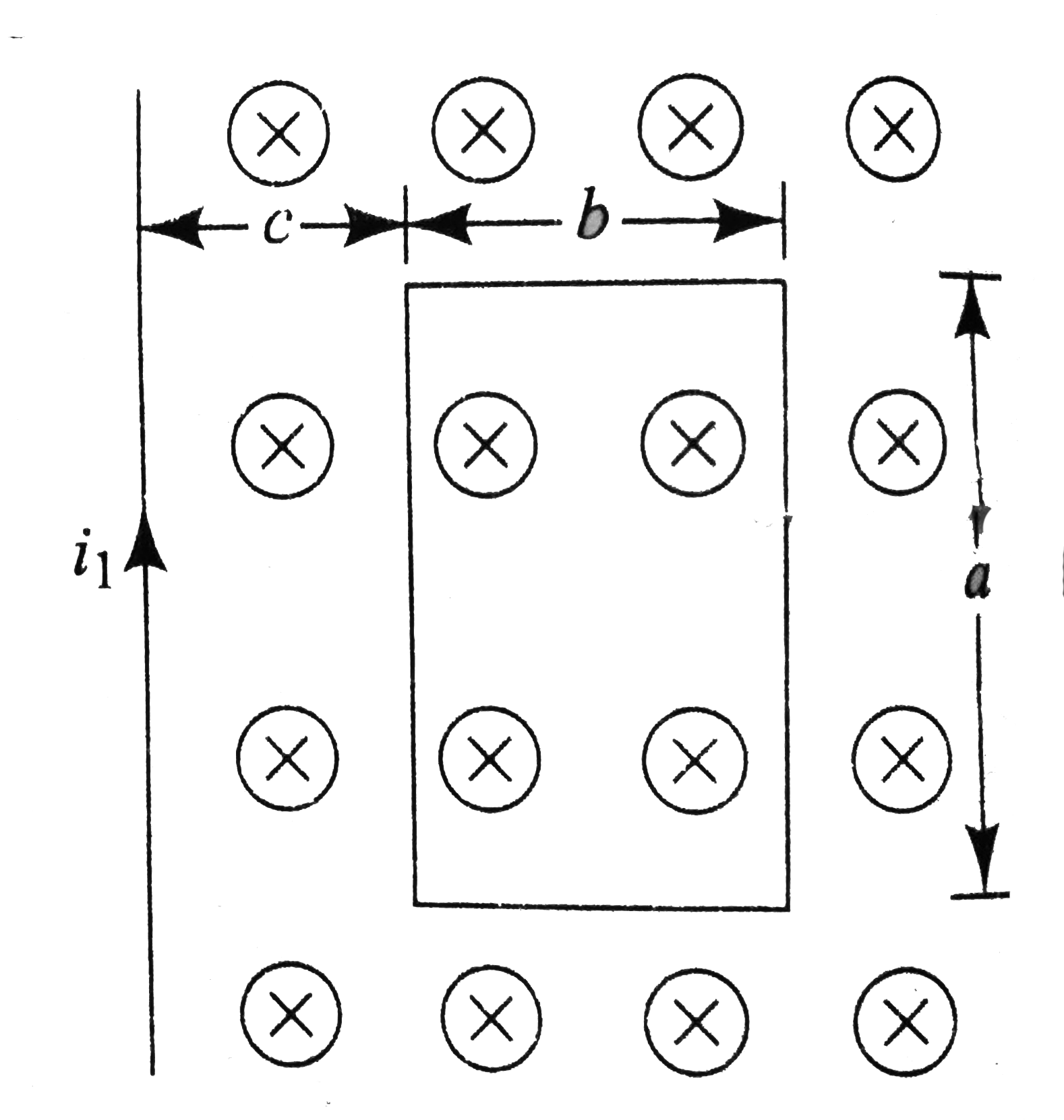
View SolutionFigure shows a rectangular coil near a long wire. The mutual inductance of the combination is
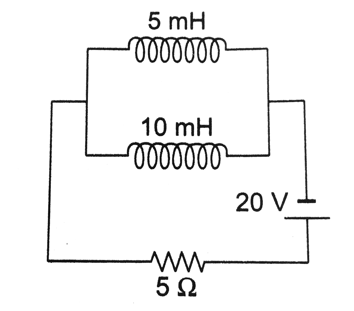
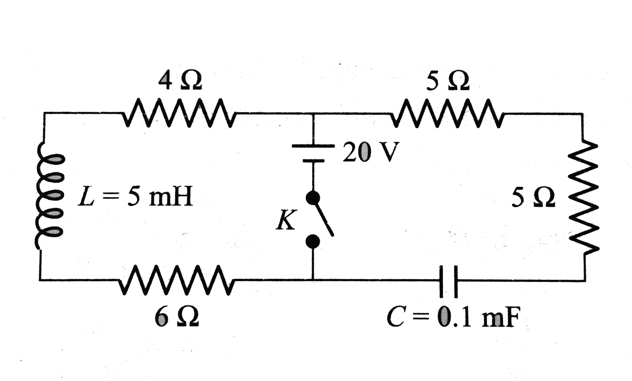
View SolutionIn the given circuit, find the current through the `5 mH` inductor in steady state.
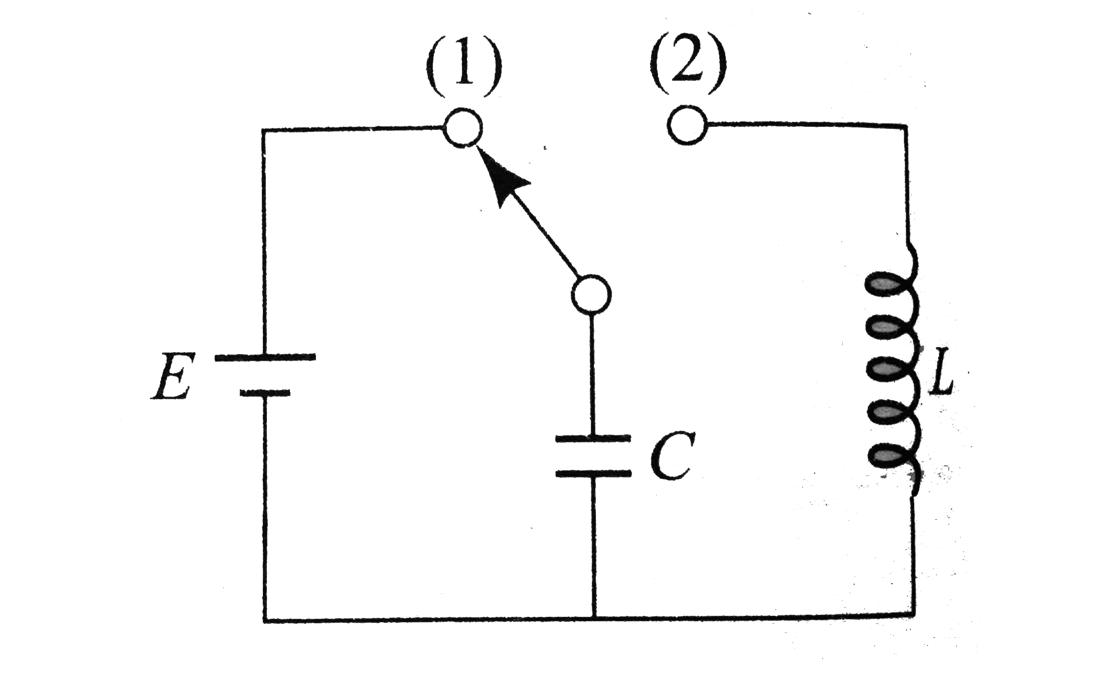
View SolutionIn the following electrical network at `t = lt 0` Fig key is placed on (1) till the capacitor got fully charged. Key is placed on (2) at `t = 0`. Time when the energy in both the same for the time is
View SolutionThe total heat produced in resistor `r` in an `RL` circuit when the current in the inductor decreases from `I_(o)` to `0` is
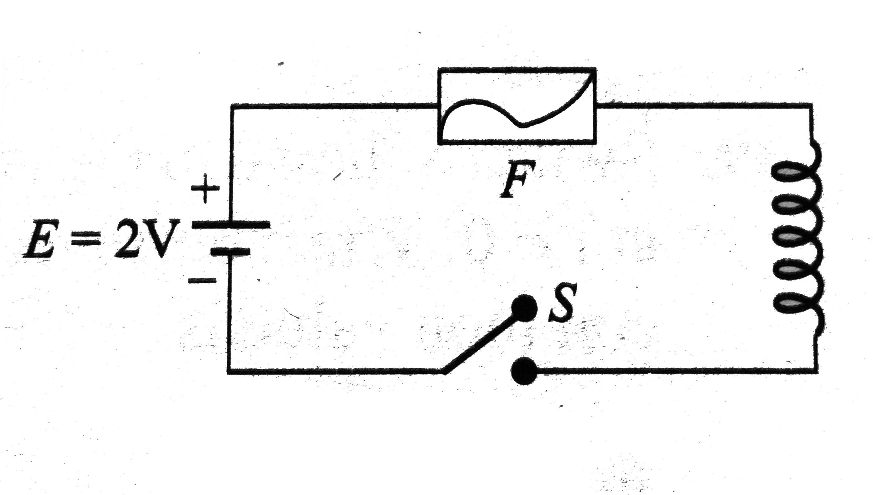
View SolutionIn the circuit shows Fig the cell is ideal. The coil has an inductance of `4 H` and zero resistance. `F` is a fuse of zero resistance and will blow when the current through it reaches `5 H`. The switch is closed at `t= 0`. The fuse will blow
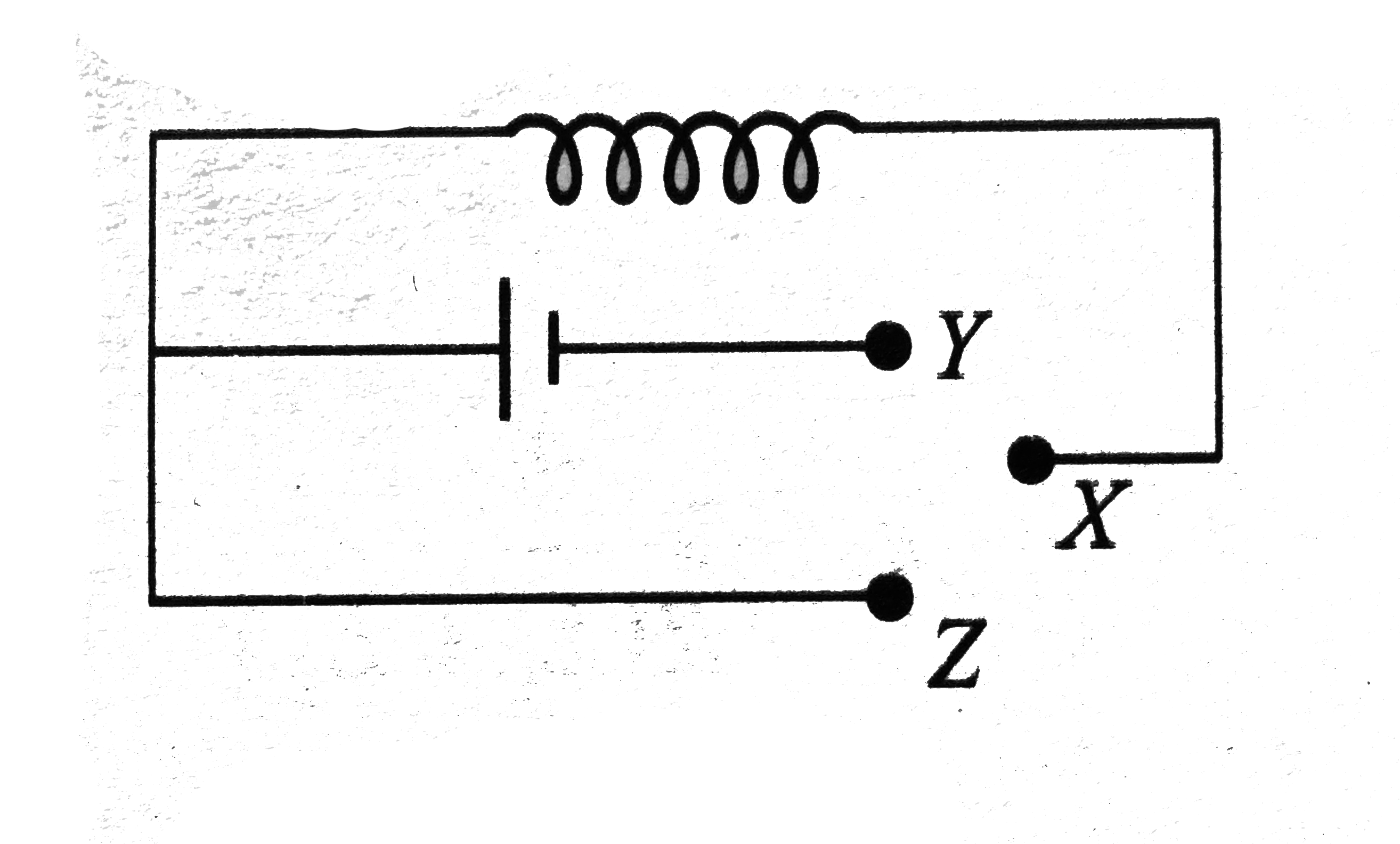
View SolutionIn the circuit shows Fig the coil has inductance and resistance. When `X` is joined to `Y`, the time constant is `t` during the growth of current. When the steady state is reached, heat is produced in the coil at a rate `P`. `X` is now joined to `Z`. After joining `X` and `Z`:
View SolutionA long solenoid having `200` turns per centimeter carries a current of `1.5 A`. At the center of the solenoid is placed a coil of `100` turns of cross-sectional area `3.14 xx 10^(-4) m^(2)` having its axis parallel to the field produced by the solenoid. When the direction of current in teh solenoid is reversed within `0.05 s`, the induced emf in the coil is
View SolutionIn an `LR` circuit connected to a battery, the rate at which energy is stored in the inductor is plotted against time during the growth of current in the circuit. Which of the following best represents the resulation curve?
View SolutionTwo coils are at fixed location: When coil 1 has no current and the current in coil 2 increase at the rate of `15.0 A s^(-1)`, the emf in coil 1 is `25 mV`, when coil 2 has no current and coil 1 has a current of `3.6 A`, the flux linkange in coil 2 is
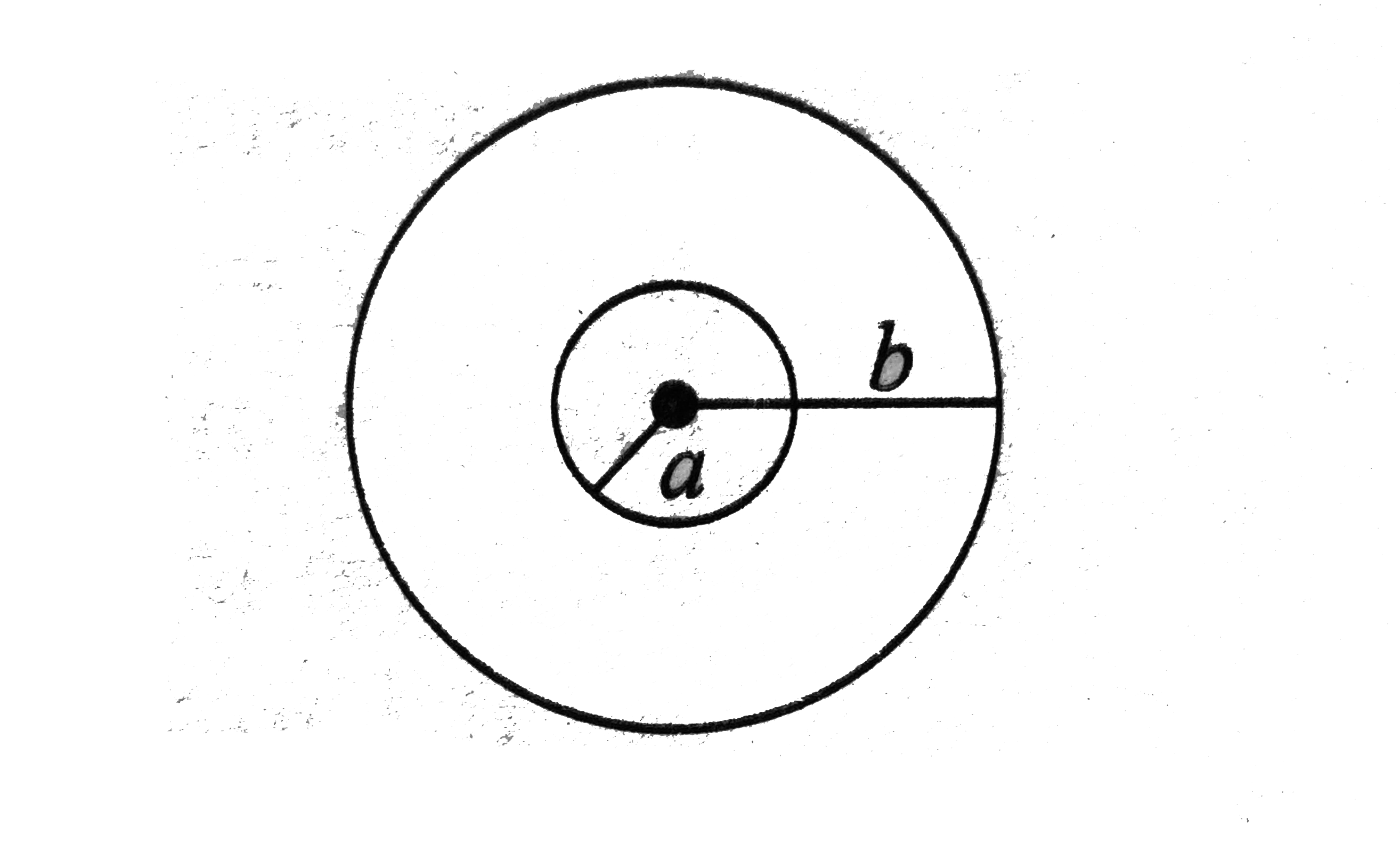
View SolutionTwo concentric and coplanar coils have redii a and `b ( gt gt a)` as shows in Fig. Resistance of the inner coil is `R`. Current in the outer coil in increased from `0` to `i`, then the total charge circulating the inner coil is
View SolutionA current `i_(0)` is flowing through an `L-R` circuit of time constant `i_(0)`. The source of the current is switched off at time `t = 0`. Let `r` be the value of `(-di//dt)` at time `t = 0`.Assuming this rate to be constant, the current will reduce to zero in a time interval of
View SolutionIn the circuit shown in figure switch `S` is closed at time `t=0`. The charge which passes through the battery in one time constant is
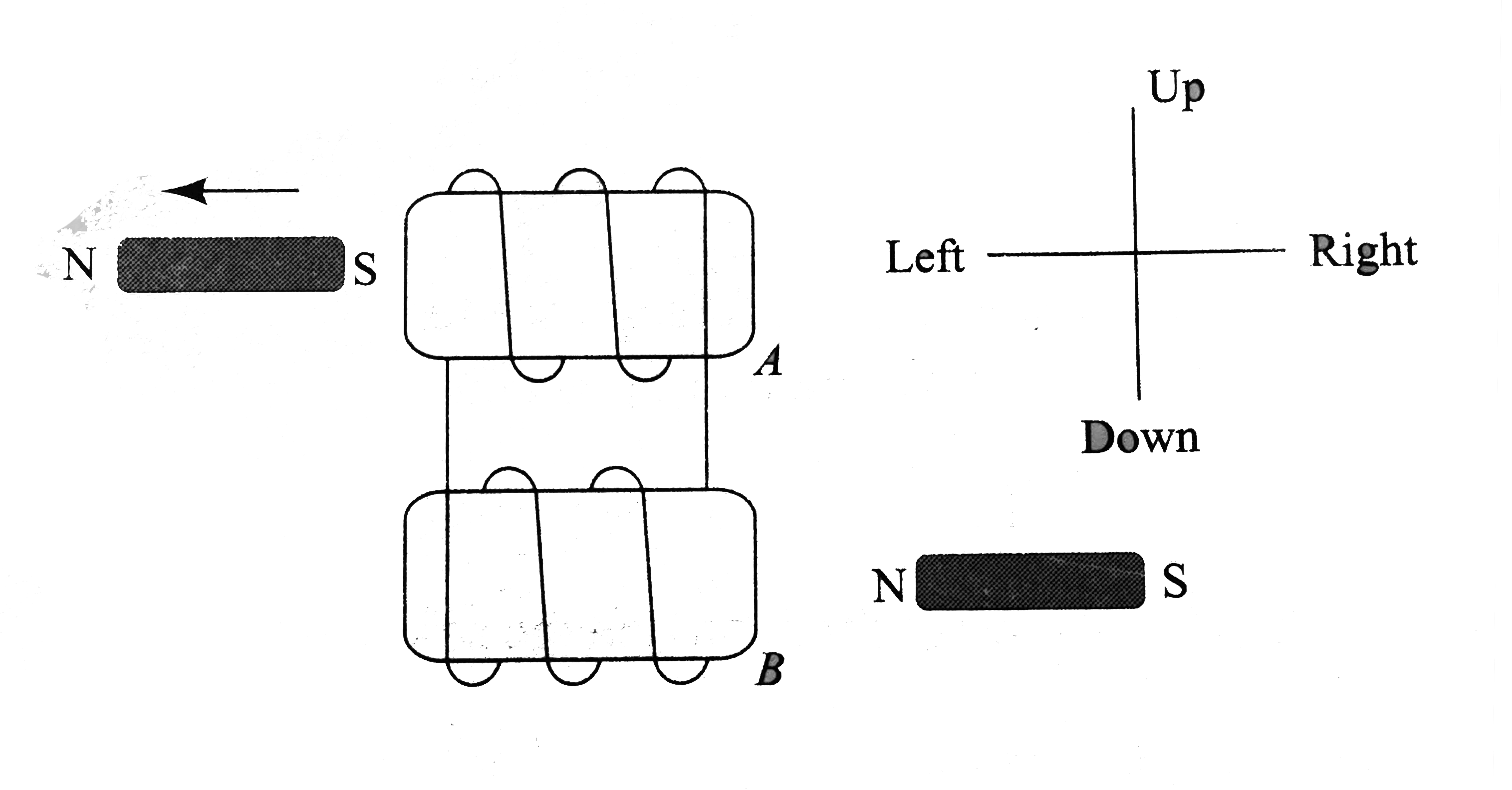
View SolutionA bar magnet was pulled away from a hollow coil `A` as shows in Fig As the south pole came out of the coil, the bar magnet next to hollow coil `B` experiened a magnetic force

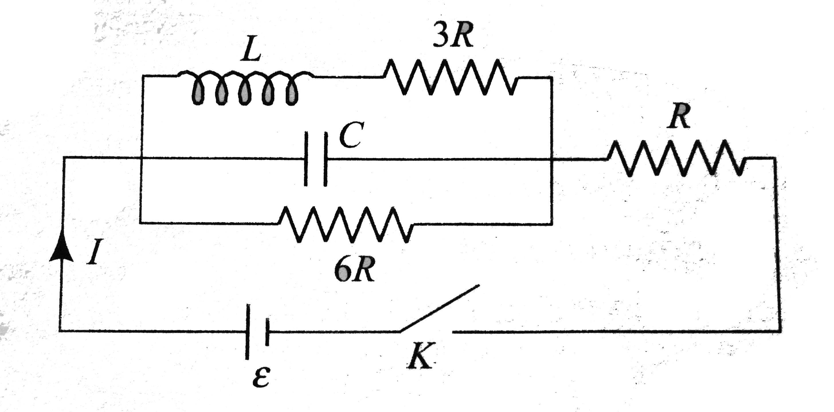
View SolutionIn the given circuit (Fig), key `K` is witched on the at `t = 0`. The ratio of current `i` through the cell at `t = 0` to that at `t = oo` will be
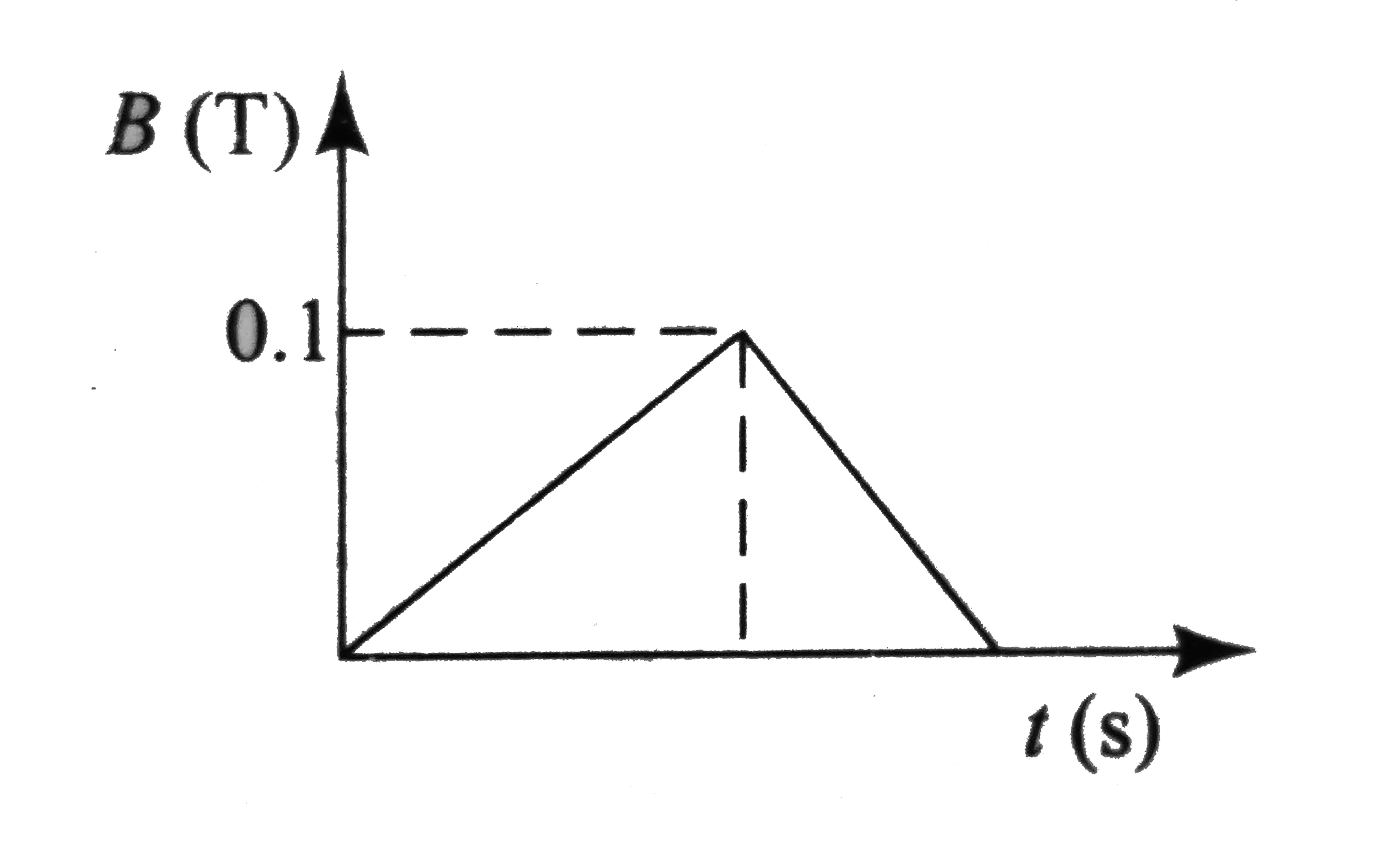
View SolutionA closed loop of cross-sectional area `10^(-2) m^(2)` which has inductance `L = 10 mH` and negligible resistance is placed ti time- varying magnetic field. Figure shows the variation of `B` with time for the intervel `4 s`. The field is perpendicular to the plane of the loop (given at `t = 0`, `B = 0`, `I = 0)`. The value of the maximum current induced in the loop is
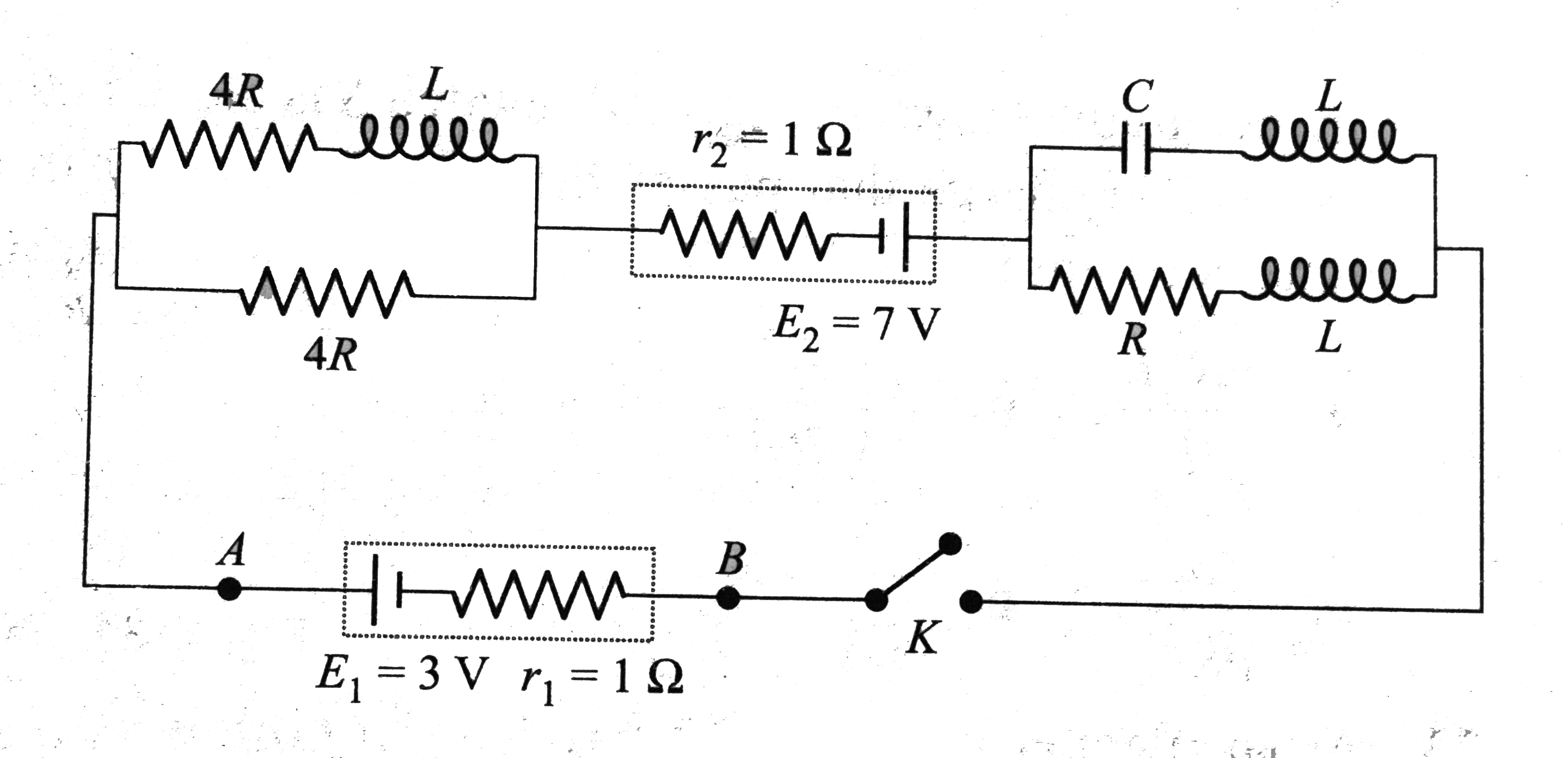
View SolutionIn Fig. key `K` is closed at `t = 0`. After a long time, the potential difference between `A` and `B` is zero, the value of `R` will be `[r_(1) = r_(2) = 1 Omega, E_(1) = 3 V` and `E_(2) = 7 V`, `C = 2 mu F`, `L = 4 mH`, where `r_(1)` and `r_(2)` are the internal resistances of cells `E_(1)` and `E_(2)`, respectively].
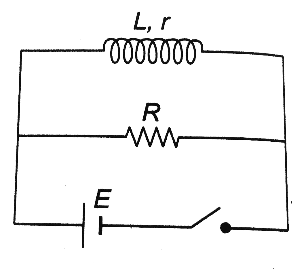
View SolutionA solenoid of inductance `L` with resistance `r` is connected in parallel to a resistance `R`. A battery of emf `E` and of negligible internal resistance is connected across the parallel combination as shown in the figure. At time `t = 0`, switch `S` is opened, calculate
(a) current through the solenoid after the switch is opened.
(b) amount of heat generated in the solenoid.
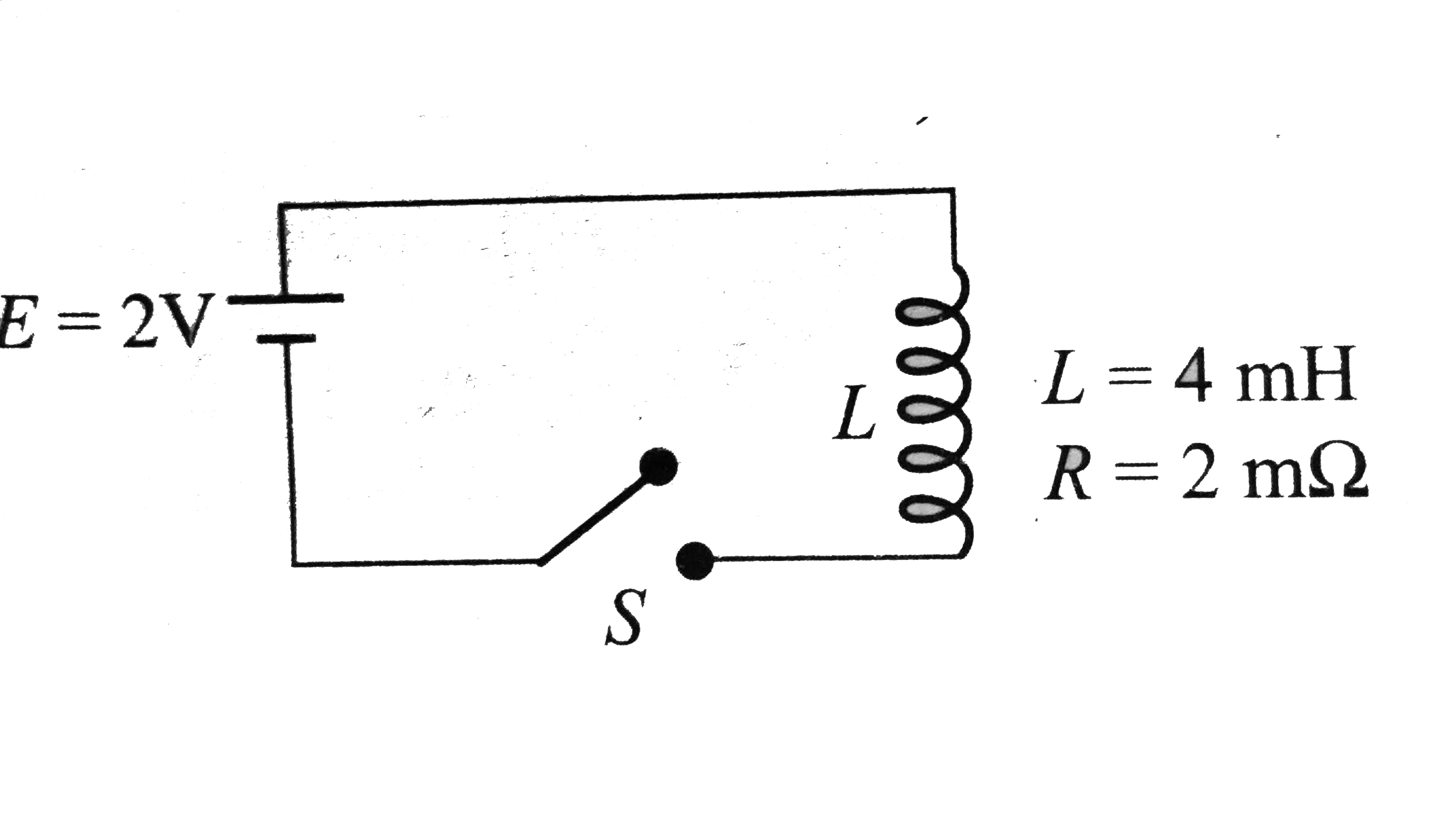
View SolutionThe cell in the circuit shows in Fig is ideal. The coil has an inductance of `4 mH` and a resistance of `2 mOmega`. The switch is closed at `t = 0`. The amount of energy stored in the inductor at `t = 2 s` is (take `e = 3)`
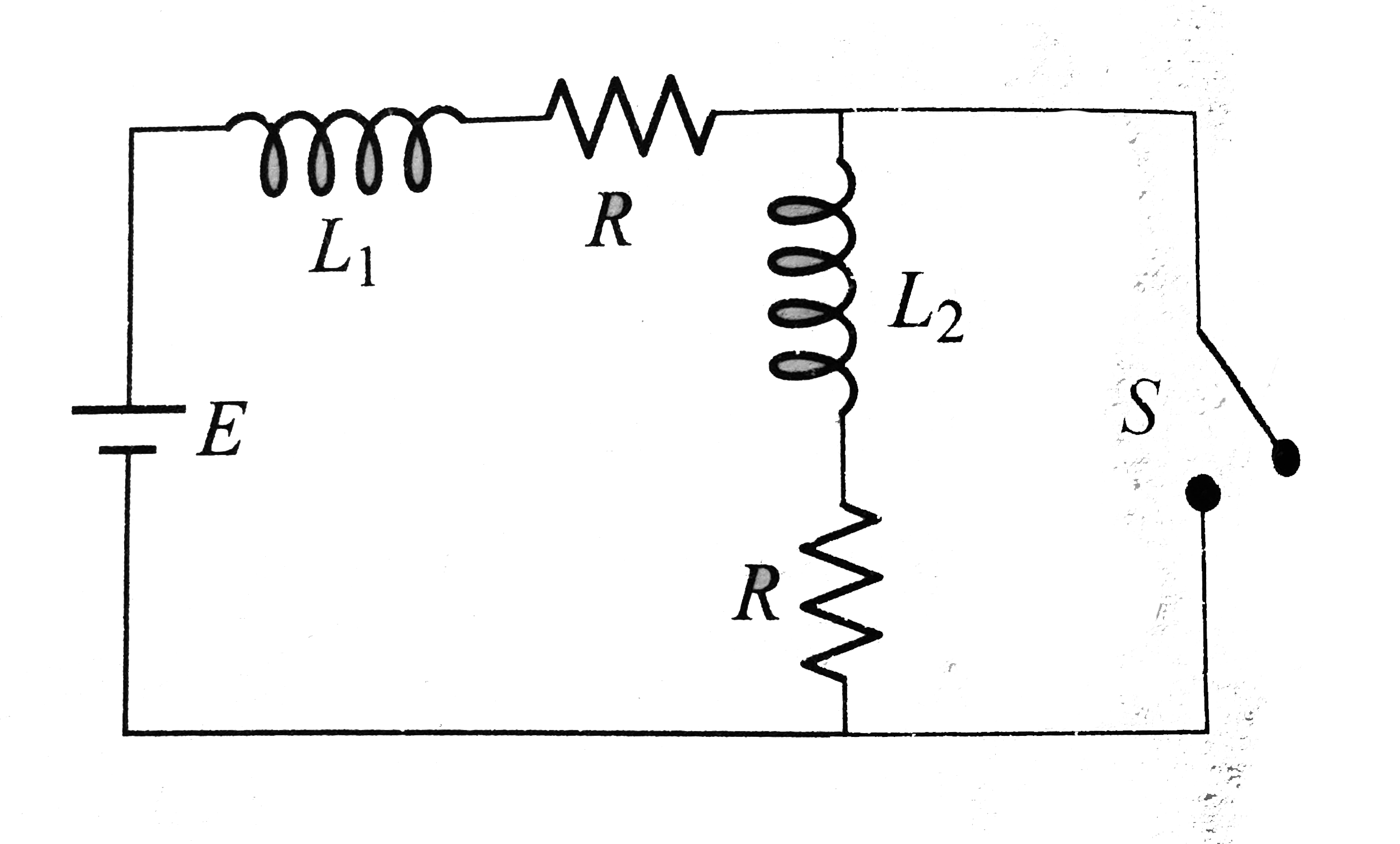
View SolutionSwitch `S` shown in Fig. is closed for `t lt 0` and is opened at `t = 0`. When currents through `L_(1)` and `L_(2)` are equal, their common value is
View SolutionIn Fig, the mutual inductance of a coil and a very long straight wire is `M`, coil has resistance `R` and self-inductance `L`. The current in the wire varies according to the law `I = at`, where `a` is a constant and `t` is the time, the time dependence of current in the coil is
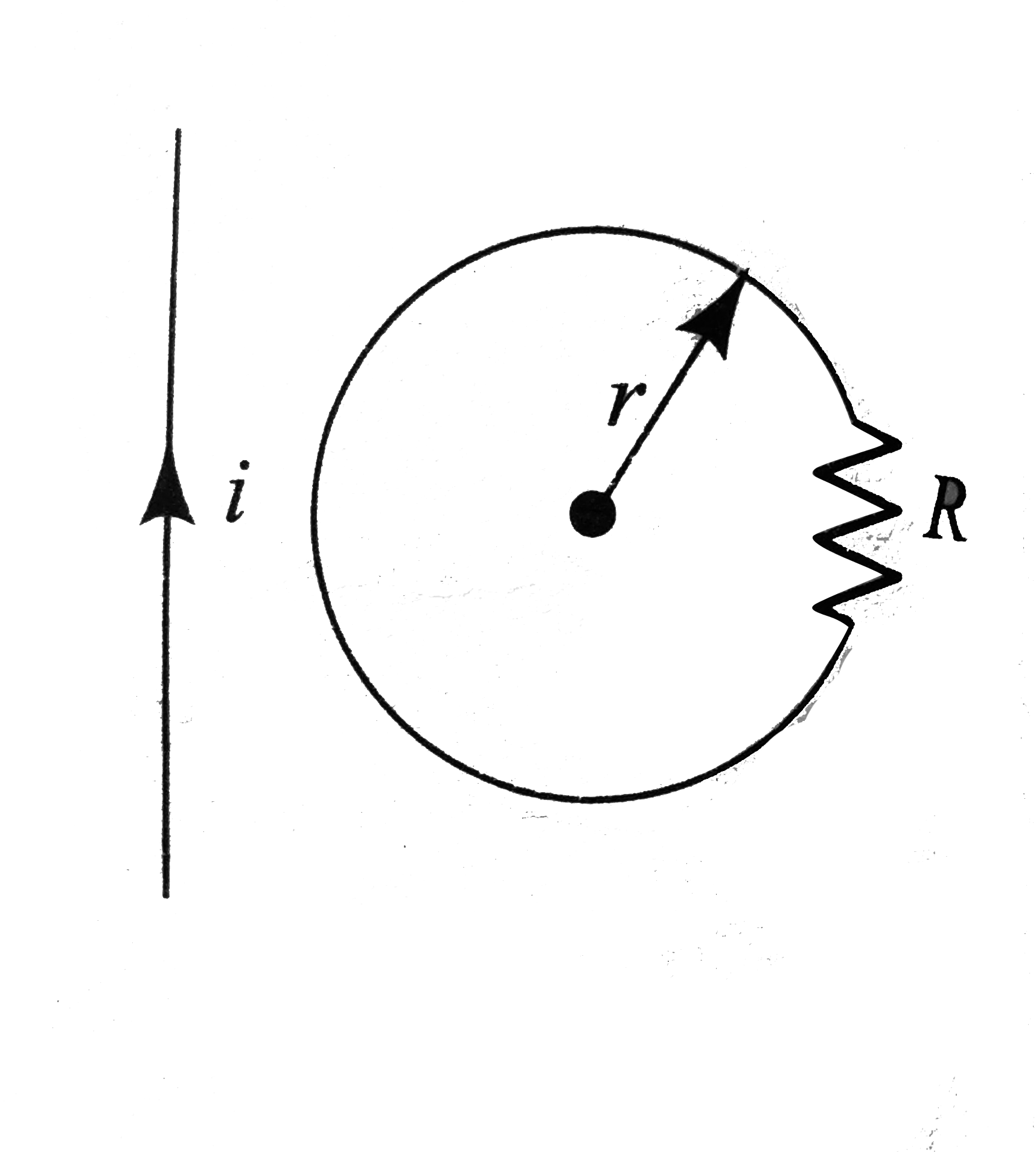
View SolutionIn the circuit shows in Fig switch `S` is shifed to position `2` from position `1` at `t = 0`, having been on position `1` for a long time. The current in the circuit just after shifting of switch will be (battery and both the inductors are ideal)
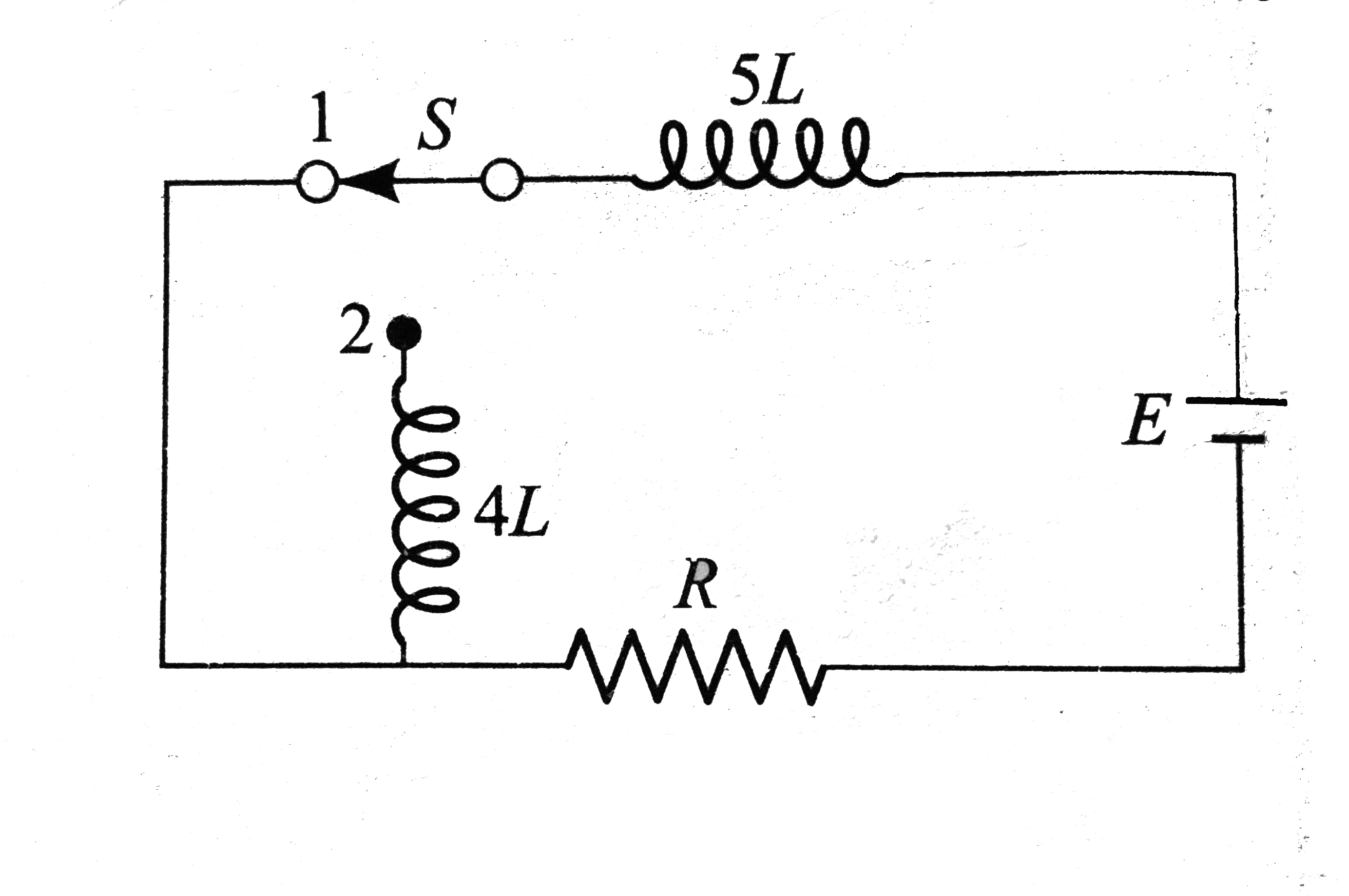
View SolutionThe capacitance in an oscilatory `LC` circuit is increased by `1%`. The charge in inductance required to restore its frequency of oscillation is to
View SolutionIn the circuit of Fig. (1) and (2) are ammeters. Just after circuit `K` is pressed to complete the circuit, the reading is
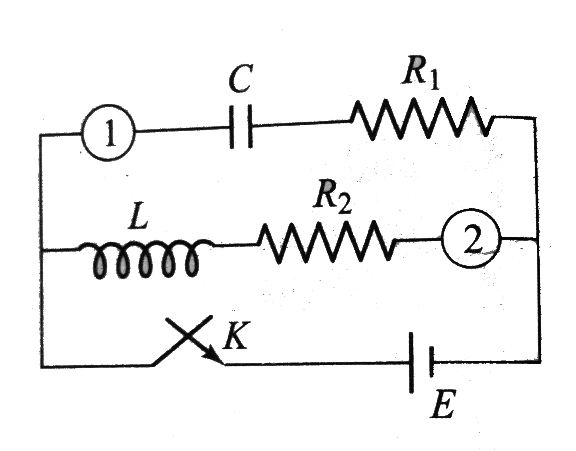
View SolutionA wire of fixed length is wound on a solenoid of length`l` and redius `r`. Its self-inductance is found to be `L`. Now, if the same wire is wound on a solenoid of length `l//2` and redius `r//2` then the self-inductance will be
View SolutionThe frequency of oscillation of current in the inductance is

View SolutionIn Fig. switch `S` is closed for a long time. At `t = 0`, if it is opened, then
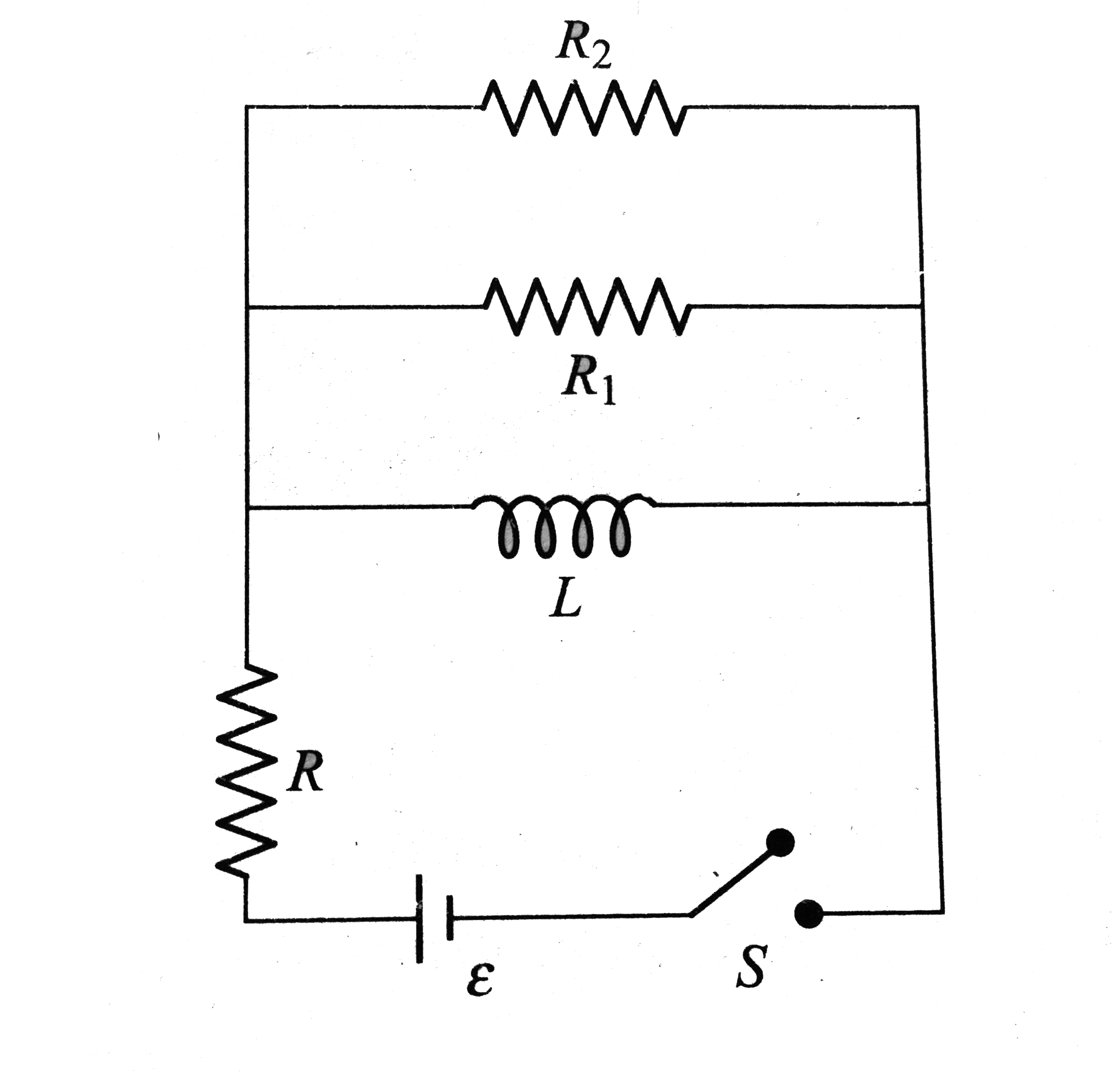
View SolutionA closed circuit of a resistor `R`, inductor of inductance `L` and a source of emf `E` are connected is series. If the inductance of the coil is abruptly decreaed to `L//4` (by removing its magnetic core), the new current immediately after this moment is (before decreasing the inductance the circuit is in steady state)
View SolutionGiven `L_(1) = 1 mH`, `R_(1) = 1 Omega`, `L_(2) = 2 mH`, `R_(2) = 2 Omega`
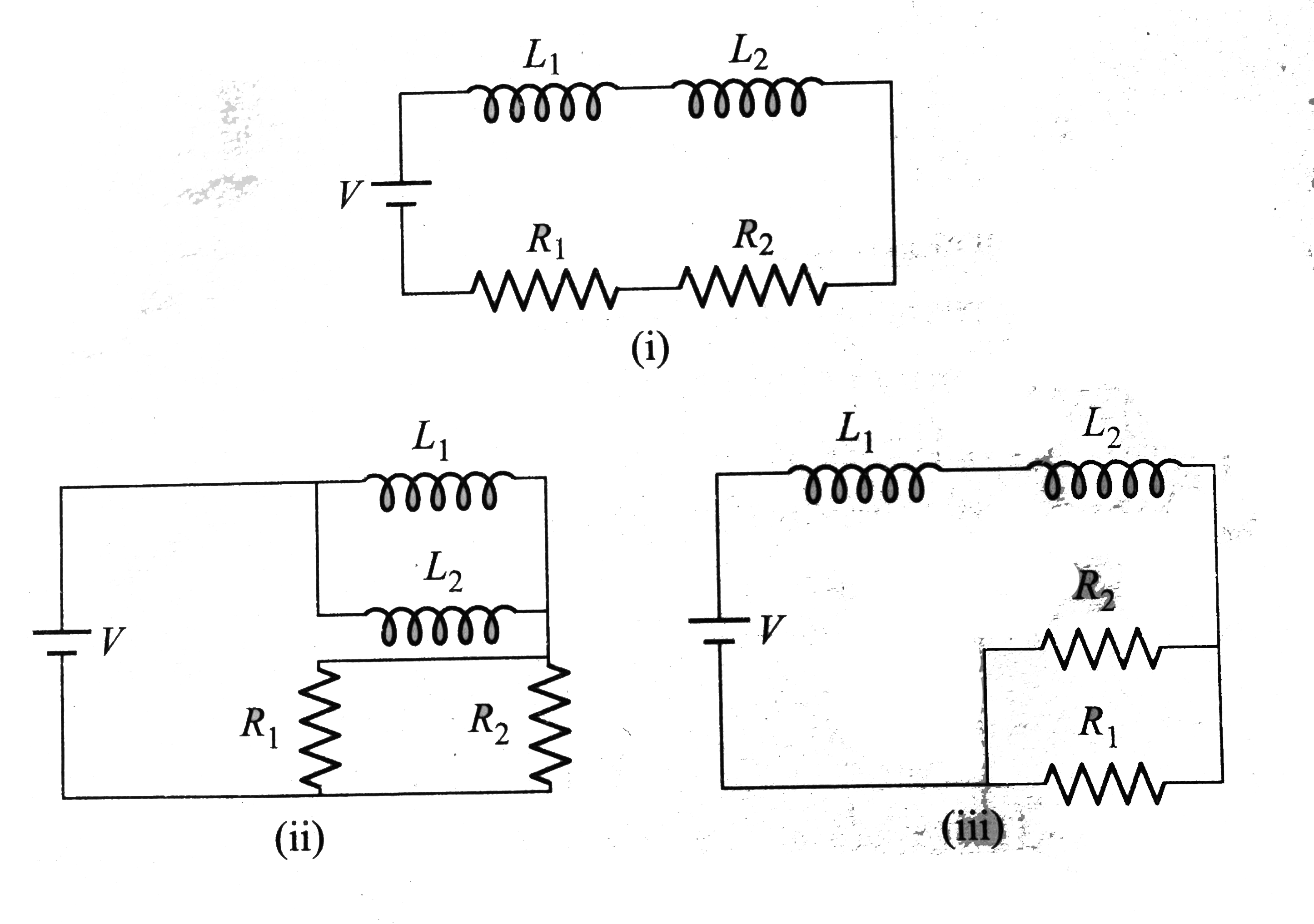


Neglecting mutual inductanec, the time constants (in ms) for circuits (i), (ii), and (iii) are
View SolutionA horizontal ring of radius `r = (1)/(2) m` is kept in a vertical constant magentic field `1 T`. The ring is collapsed from maximum area to zero area in `1 s`. Then the emf induced in the ring is
View SolutionIn the circuit shows in Fig. kay `K` is closed at `t = 0`, the current through the key at the instant `t = 10^(-3) In 2 s` is
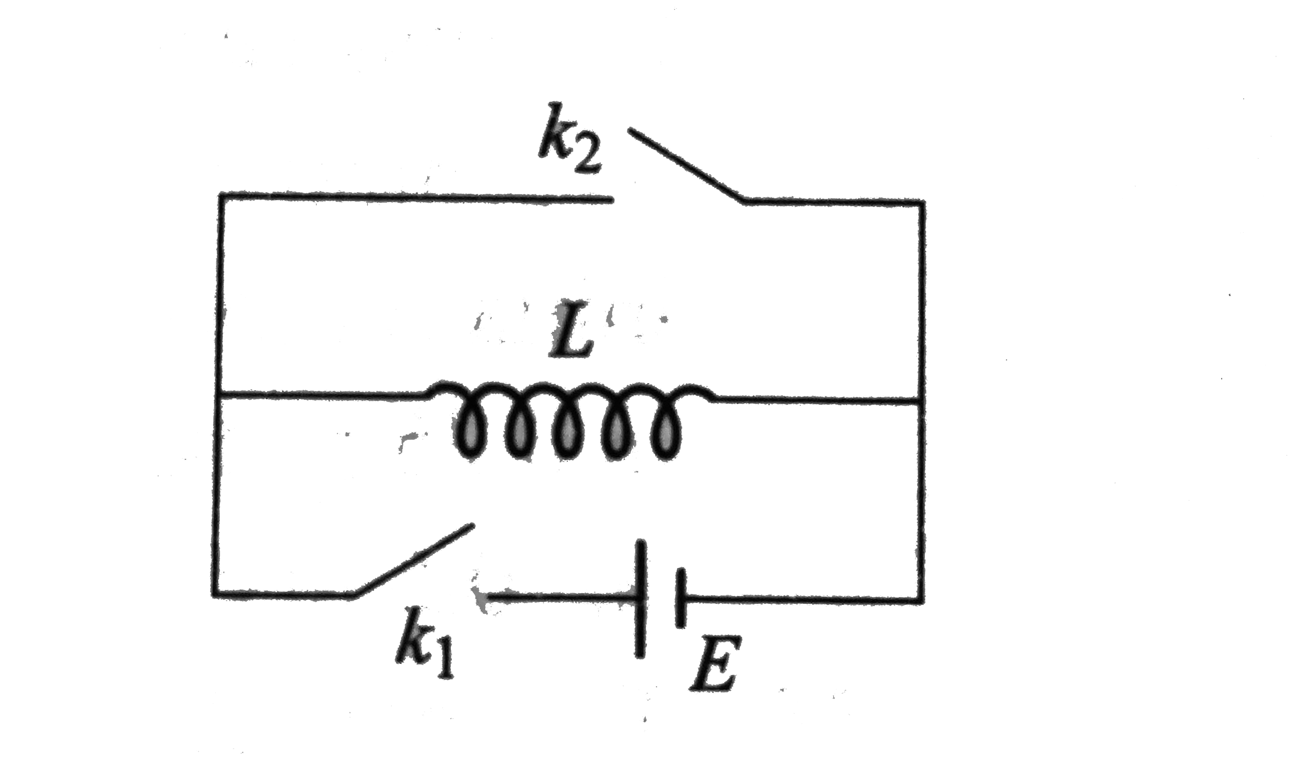
View SolutionIn the circuit shows in Fig. switch `k_(2)` is open and switch `k_(1)` is closed at `t = 0`. At time `t = t_(0)`, switch `k_(1)` is opened and switch `k_(2)` is simultaneosuly closed. The variation of inductor current with time is
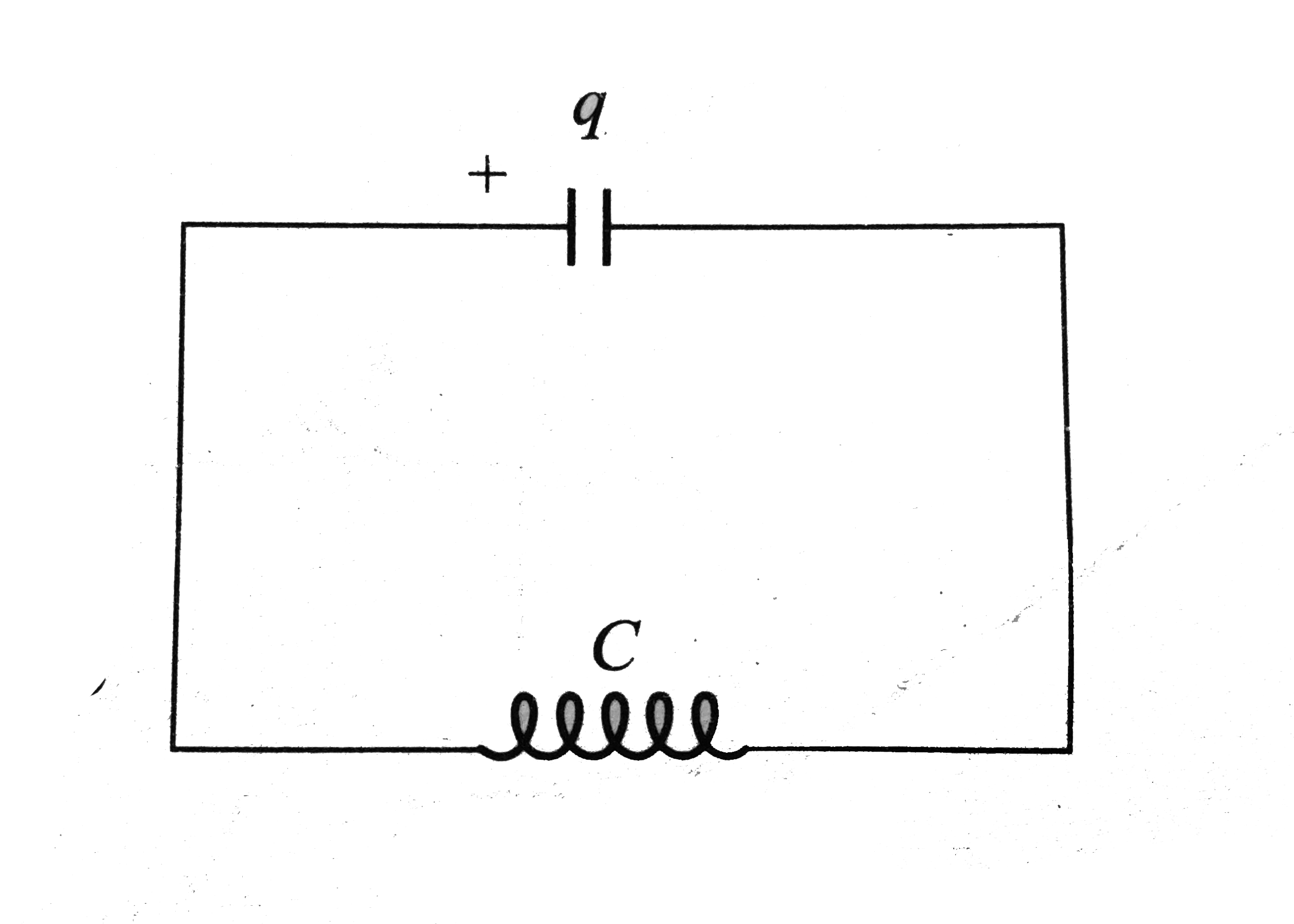
View SolutionIn an `LC` circuit shows in Fig. `C = 1 F`, `L = 4 H`. At time `t = 0`, charge in the capacitor is `4 C` and it is decreasing at the rate of `sqrt(5) C s^(-1)`. Choose the corrent statement.
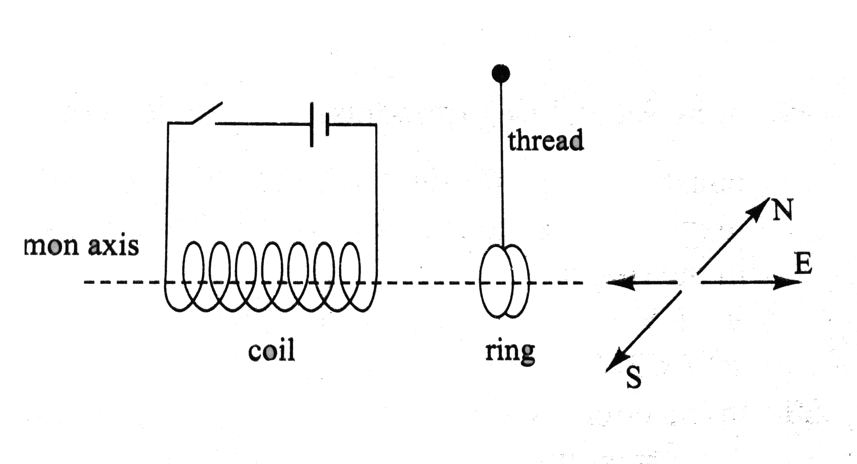
View SolutionAn aluminium ring hangs vertically from a thread with its axis pointing east-west. A coil is fixed mear to the ring and coaxial with it.
What is the initial motion of the aluminium ring when the current in the coil is switched on?
View SolutionA coil carrying a steady current is short-circuited. The current in it decreases `alpha` times in time `t_(0)`. The time constant of the circuit is
View SolutionA solenoid has `2000` turns wound over a length of `0.3 m`. Its cross-sectional area is equal to `1.2 xx 10^(-3) m^(2)`. Around its central cross-section a coil of `300` turns in wound. If an initial current of `2 A` flowing in the solenoid is reversed in `0.25 s`, the emf induced in the coil is
View SolutionTwo coils `X` and `Y` are linked such that emf `E` is induced in `Y` when the current in `x` is changing at the rate `I' (= dI//dt)`. If a current `I_(0)` is now made to flow through `Y`, the flux linked with `X` will be
View SolutionThe time constant of an inductance coil is `2 xx 10^(-3) s`. When a `90-Omega` resistance is joined in series, the same constant becomes `0.5 xx 10^(-3) s`. The inductance and resistance of the coil are
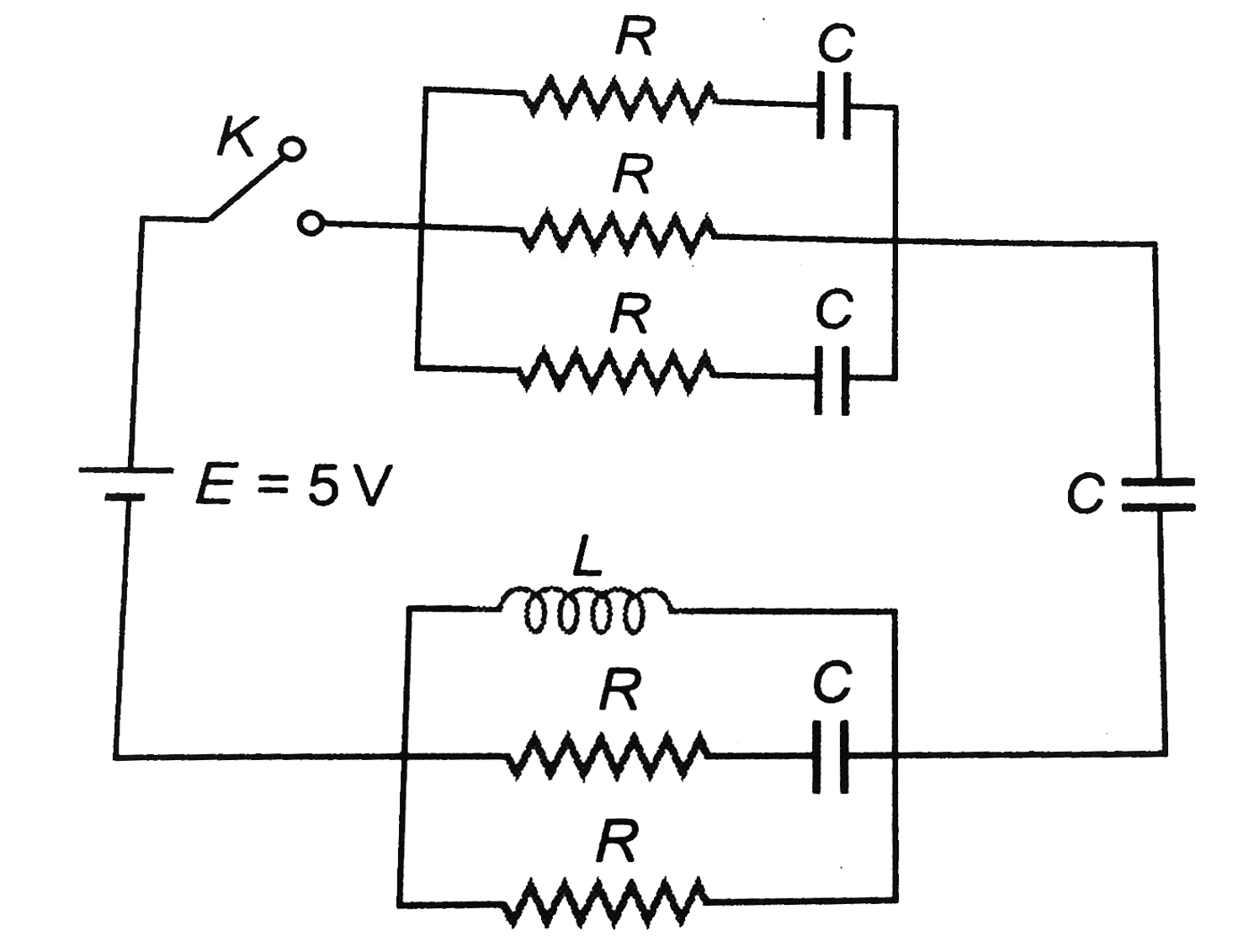
View SolutionFind the current passing through battery immediately after key `(K)` is closed. It is given that initially all the capacitors are uncharged. (Given that `R=6Omega` and `C=4muF)`
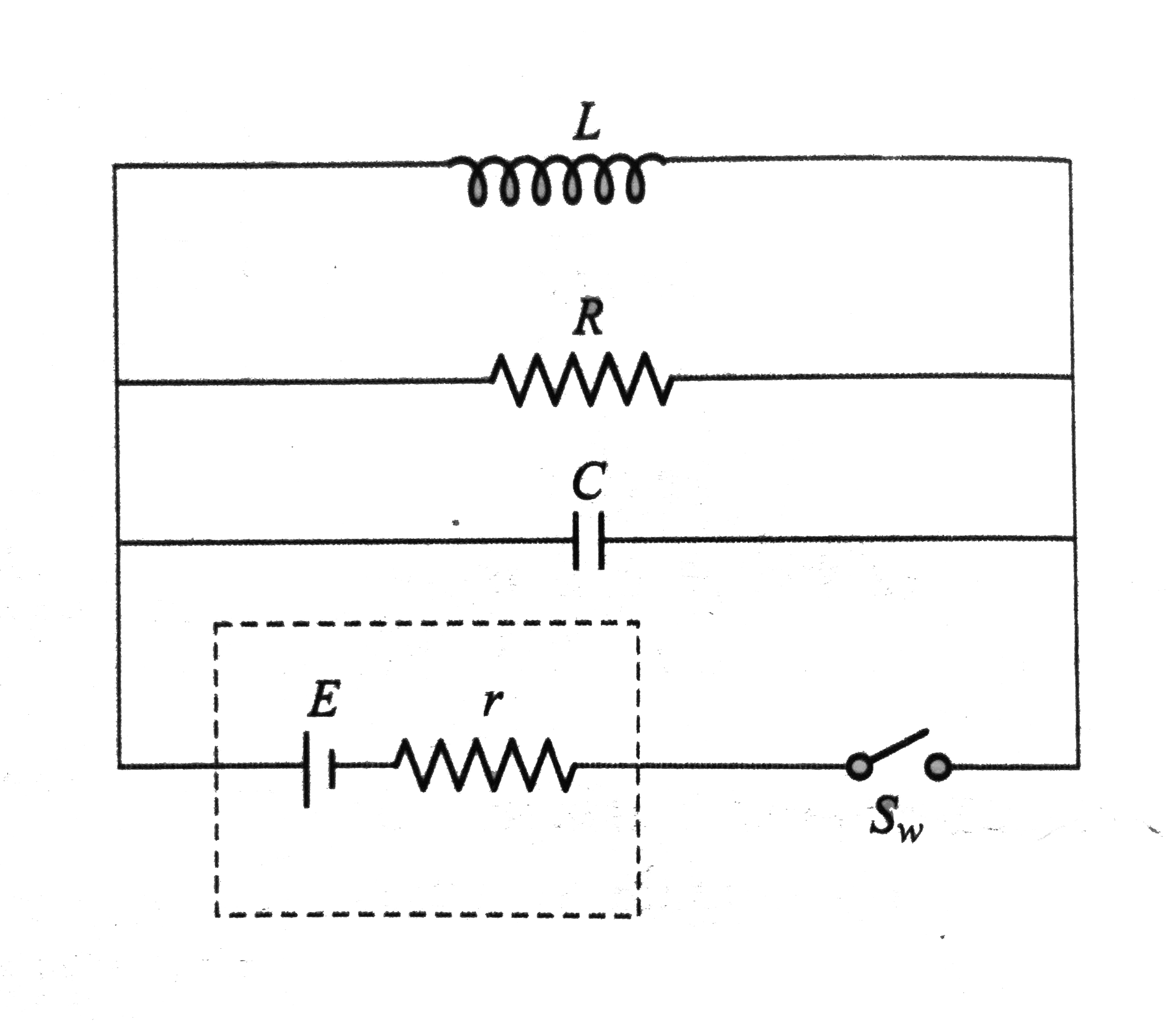
View SolutionA pure inductor `L`, a capactior `C` and a resistance `R` are connected across a battery of emf `E` and internal resistance `r` as shows in Fig. Switch `S_(W)` is closed at `t = 0`, select the correct altermative (S).
View SolutionA simple `LR` circuit is connected to a battery at time `t = 0`. The energy stored in the inductor reaches half its maximum value at time
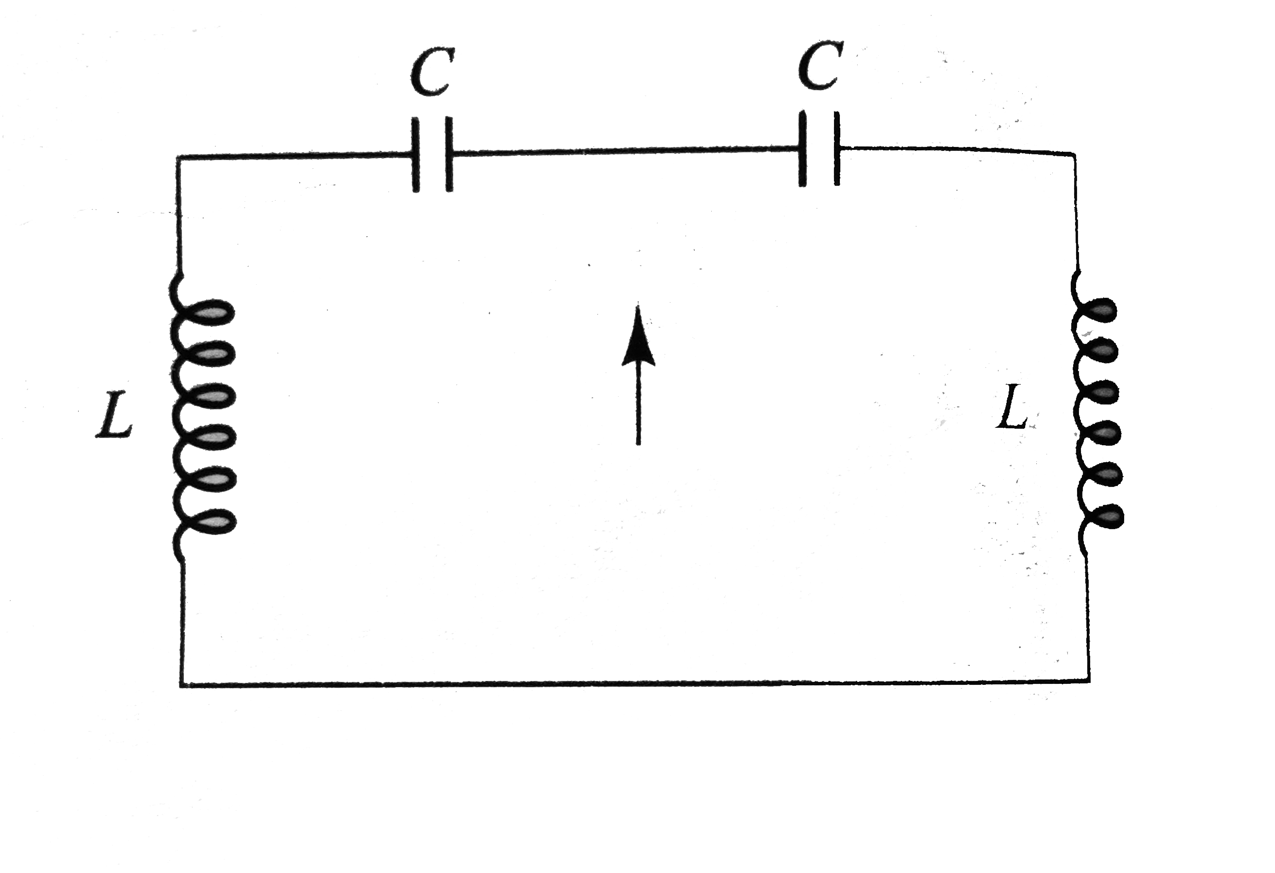
View SolutionThe natural frequency of the circuit shows in Fig. is
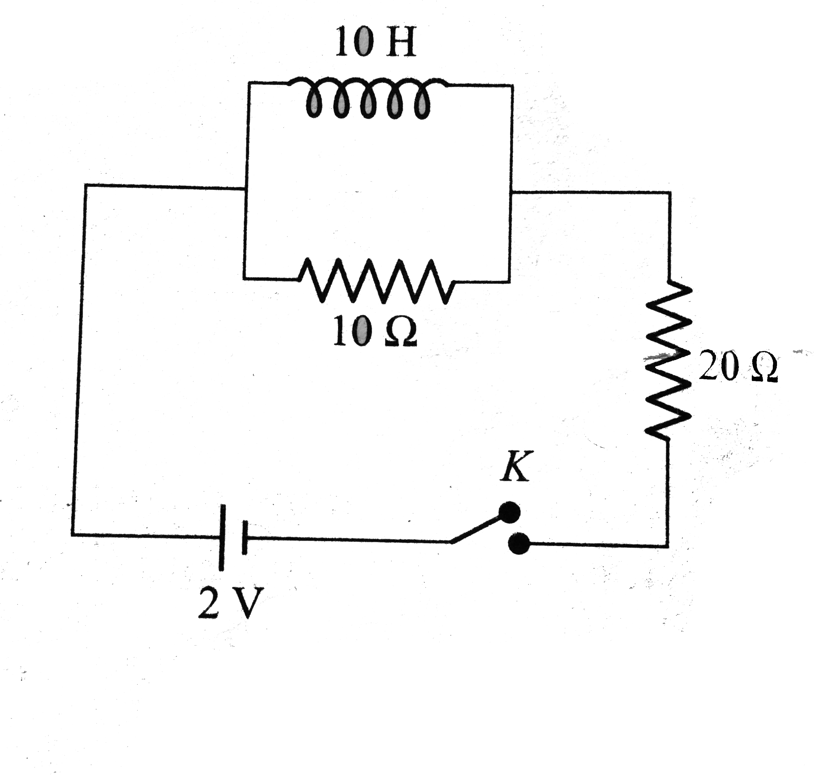
View SolutionTwo resistors of `10 Omega` and `20 Omega` and an ideal inductor of `10 H` are connected to a `2 V` battery as shows in Fig. key `K` is inserted at time `t = 0`. The initial `(t = 0)` and final `(t rarr oo)` currents through the battery are
View SolutionA square conducting loop of side `L` is situated in gravity free space. A small conducting circular loop of redius `r (rlt lt L)` is placed at the center of the square loop, with its plane perpendicular to the plane of the square loop. The mutual inductance of the two coils is
View SolutionThere is a conducting ring of radius `R`. Another ring having current `i` and radius `r (r lt lt R)` is kept on the axis of bigger ring such that its center lies on the axis of bigger ring at a distance `x` from the center of bigger ring and its plane is perpendicular to that axis. The mutual inductance of the bigger ring due to the smaller ring is
View SolutionThe capacitor of an oscillatory circuit of frequency `10000 Hz` is enclosed in a container. When the container is evacuated, the frequency changes by`50 Hz`, the delectric constant of the gas is
View Solution
Exercises (single Correct ) questions and complete solutions for chapter INDUCTANCE of CENGAGE PHYSICS (HINGLISH) of Class 12
All Exercises from CENGAGE PHYSICS Class 12 PHYSICS INDUCTANCE
- Archives (fills In The Blanks)
- Archives (integer)
- Archives (linked Compreshension)
- Archives (multiple Correct)
- Archives (single Correct )
- Comprehension Type
- Concept Based
- Exercise 4.1
- Exercises (assertion-reasoning)
- Exercises (integer)
- Exercises (linked Compreshension)
- Exercises (multiple Correct )
- Exercises (single Correct )
- Exercises (subjective)
- Illustration
- Multiple Correct Answer
- Single correct Answer Type
- Solved Examples
- Subective Type