Complete Solutions to Comprehension of chapter ELECTRIC CURRENT AND CIRCUIT of Class 12 book with complete answers and questions
| Class 12 | PHYSICS |
| Chapter | ELECTRIC CURRENT AND CIRCUIT |
| CENGAGE PHYSICS | Comprehension |
| Number Of Questions | 35 |
| Academic Year | 2023-24 |
Find the current supplied by battery in the cirucit in each case (a),(b) and (c ) as shwon in fig.

View SolutionFind the current supplied by battery in the cirucit in each case (a),(b) and (c ) as shwon in fig.
 ,
,
 ,
,

View SolutionFind the current supplied by battery in the cirucit in each case (a),(b) and (c ) as shwon in fig.
 ,
,
 ,
,

View SolutionShown two ideal voltmeters and an ammeter, which are connected across the various circuit elements. If the voltmeter connected across `9Omega` resistance reads 4.5 V, then answer the following problems.
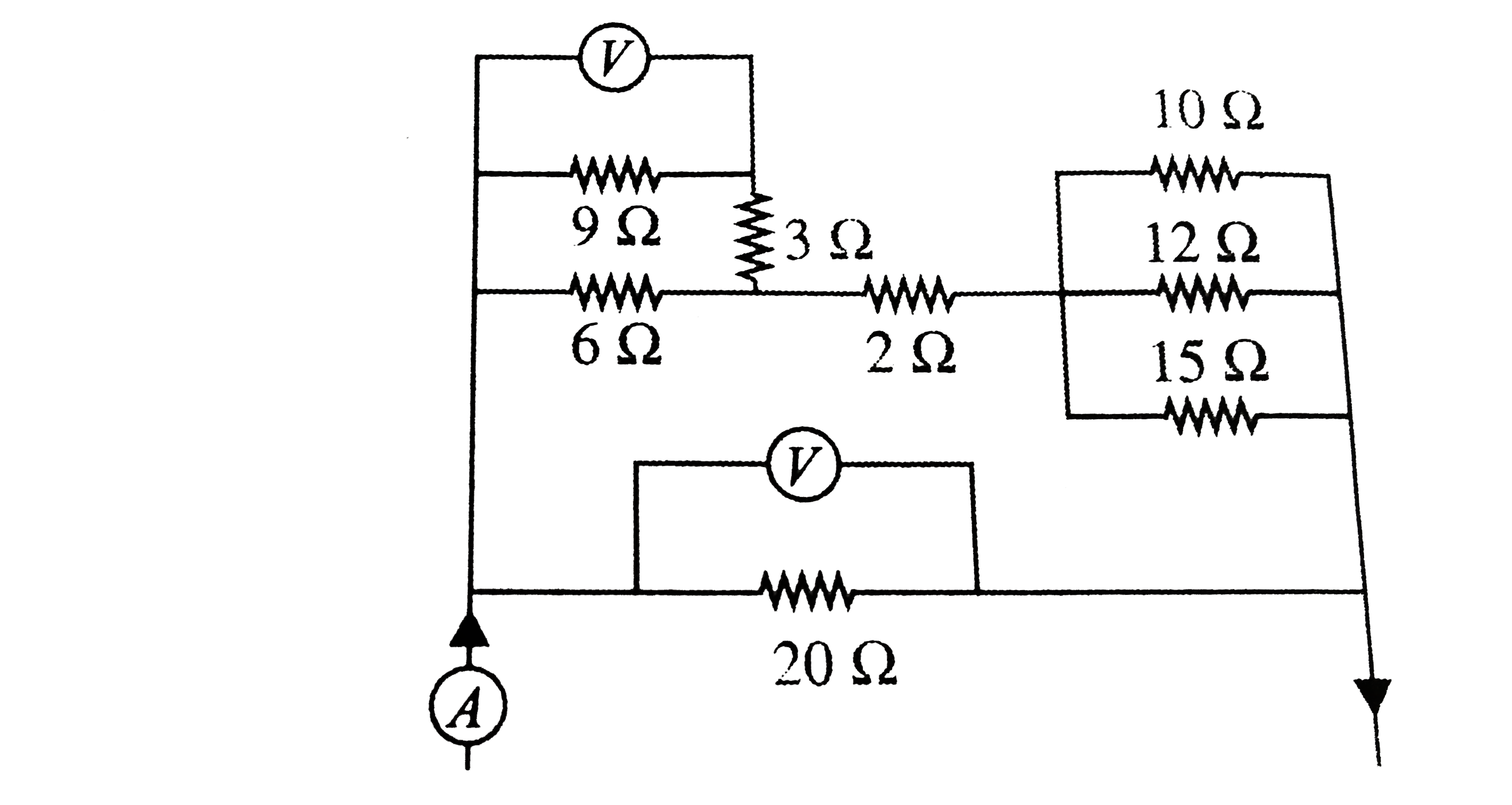
The current through `12Omega` resistance is
View SolutionShown two ideal voltmeters and an ammeter, which are connected across the various circuit elements. If the voltmeter connected across `9Omega` resistance reads 4.5 V, then answer the following problems.
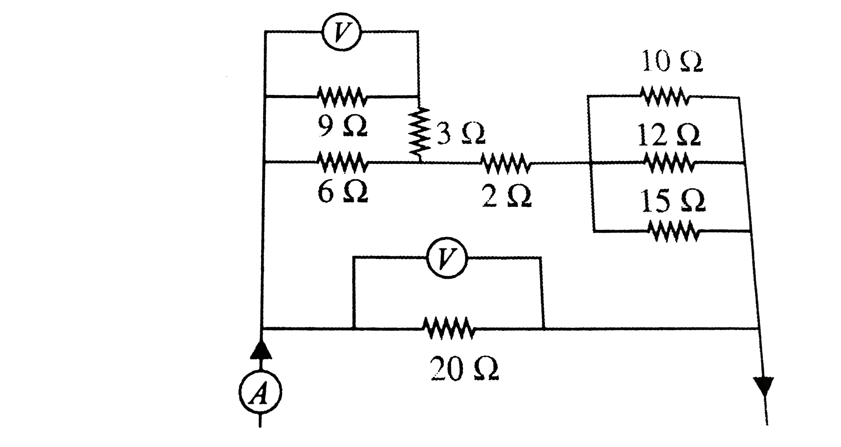
The reading of the voltmeter connected across `20Omega` resistance is
View SolutionShown two ideal voltmeters and an ammeter, which are connected across the various circuit elements. If the voltmeter connected across `9Omega` resistance reads 4.5 V, then answer the following problems.
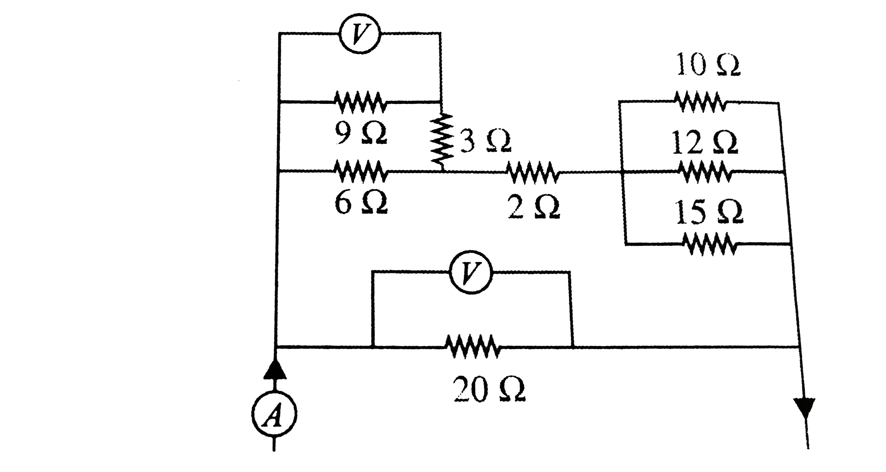
The reading of the ammeter is
View SolutionA network of resistance is constructed with `R_1 and R_2` as shown in fig. The potential at the points 1,2,3 …., N are `V_1, V_2,V_3,…,V_n,` respectively, each having a potential k times smaller then the previous one.

The ratio `R_1//R_2` is
View SolutionA network of resistance is constructed with `R_1 and R_2` as shown in fig. The potential at the points 1,2,3 …., N are `V_1, V_2,V_3,…,V_n,` respectively, each having a potential k times smaller then the previous one.

The ratio `R_2//R_3` is
View SolutionA network of resistance is constructed with `R_1 and R_2` as shown in fig. The potential at the points 1,2,3 …., N are `V_1, V_2,V_3,…,V_n,` respectively, each having a potential k times smaller then the previous one.

The current that passes through the resistance `R_2` nearest to the `V_0` is
View SolutionRelation between current in a conductor and time is shown in fig.
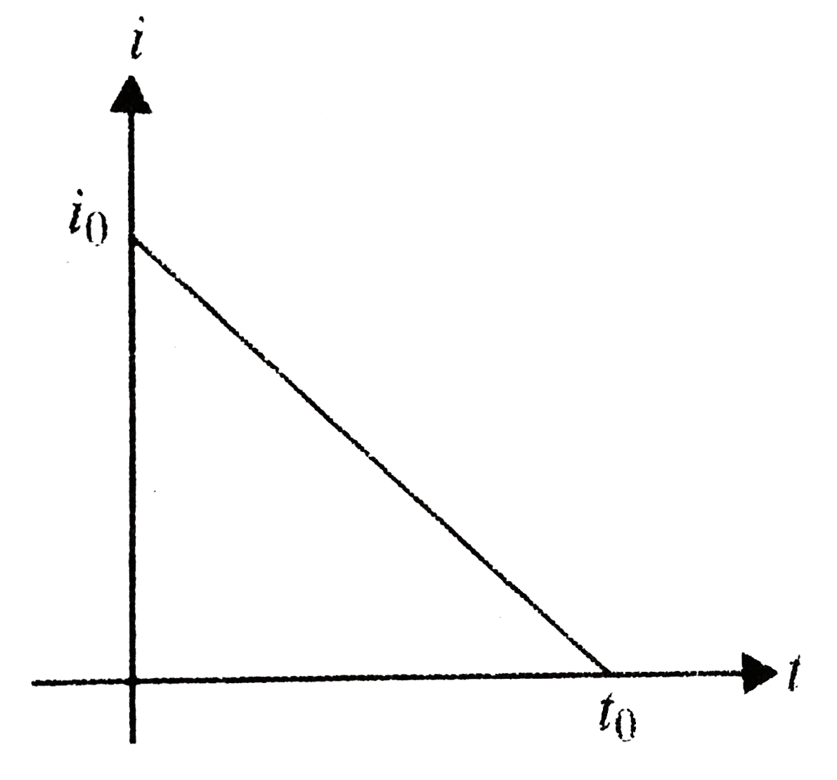
Total charge flowing through the conductor is
View SolutionRelation between current in a conductor and time is shown in fig.
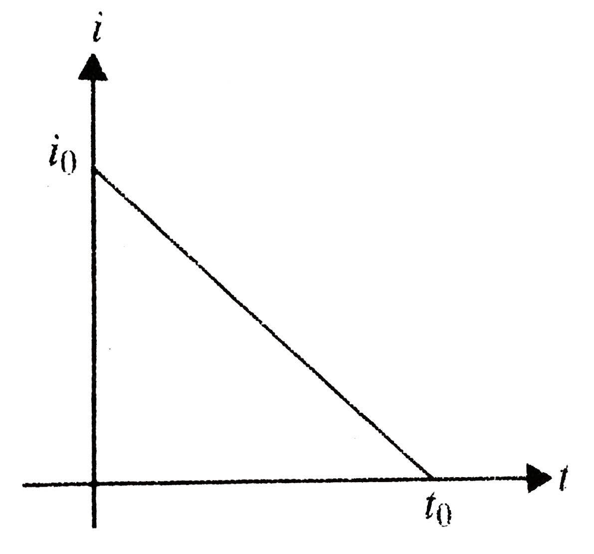
Write the expression of current in terms of time.
View SolutionRelation between current in a conductor and time is shown in fig.
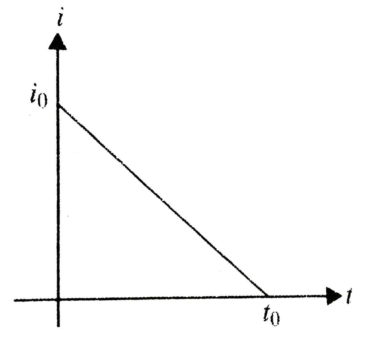
If the resistance of the conductor is R, then the total heat disspipated across resistance R is
View SolutionConsider the circuit shwon in fig. The circuit is in steady state.
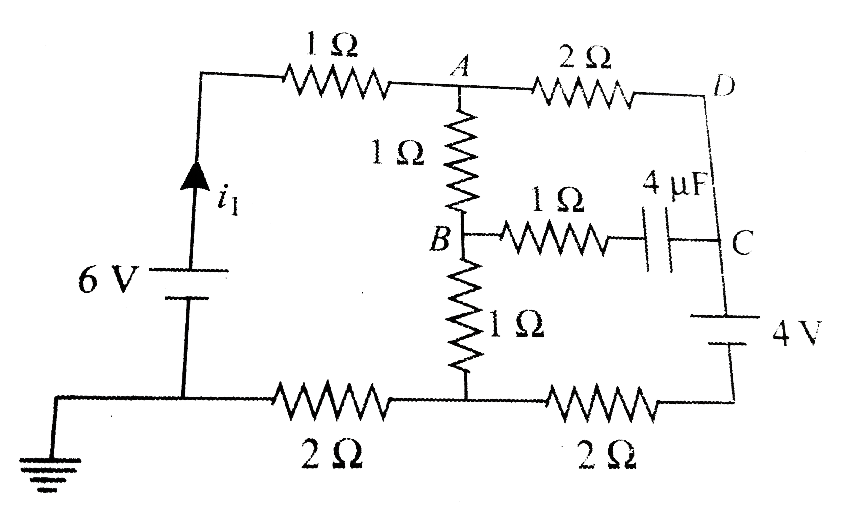
The value of `i_1` is
View SolutionConsider the circuit shwon in fig. The circuit is in steady state.
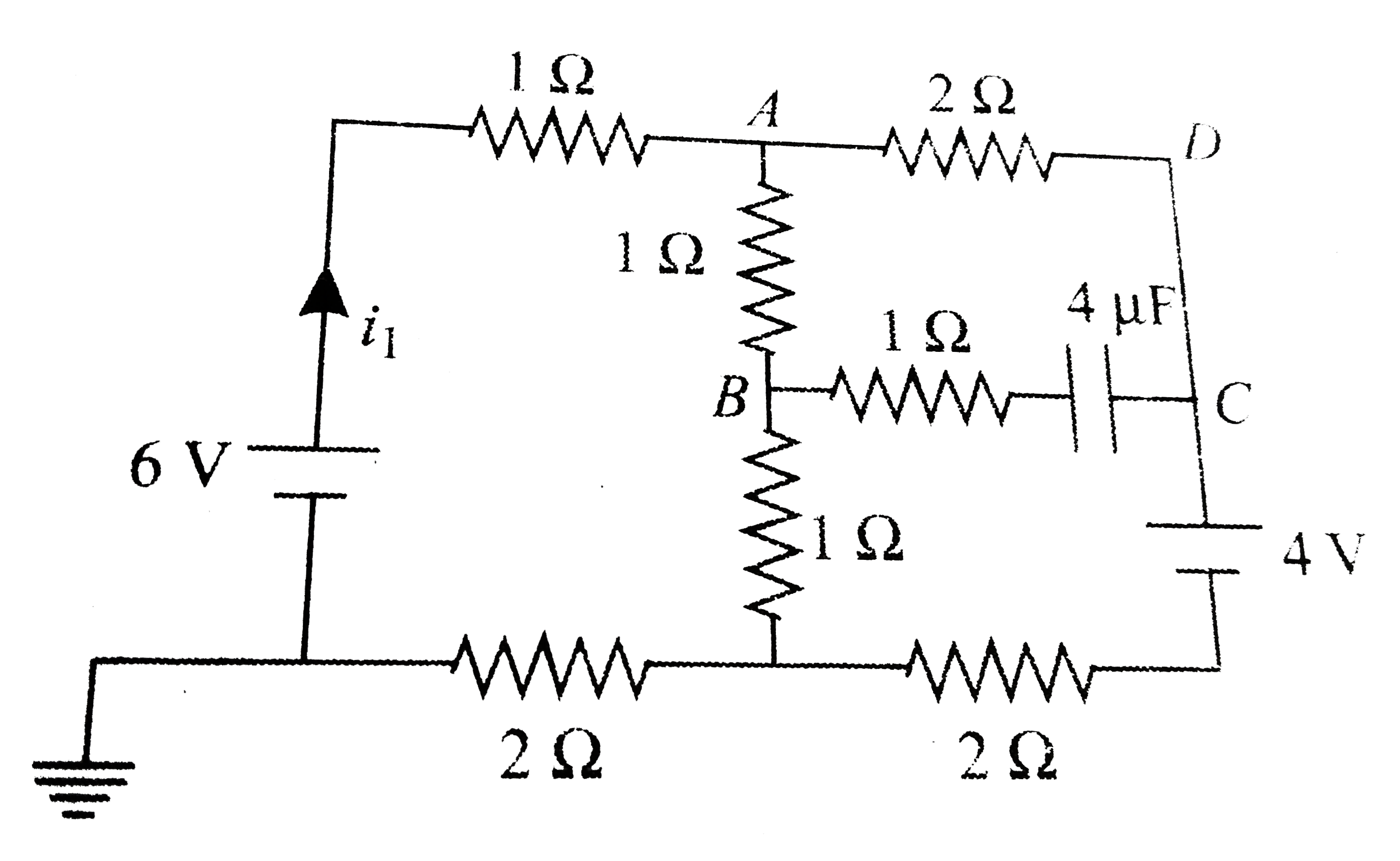
The potential of point B is
View SolutionConsider the circuit shwon in fig. The circuit is in steady state.
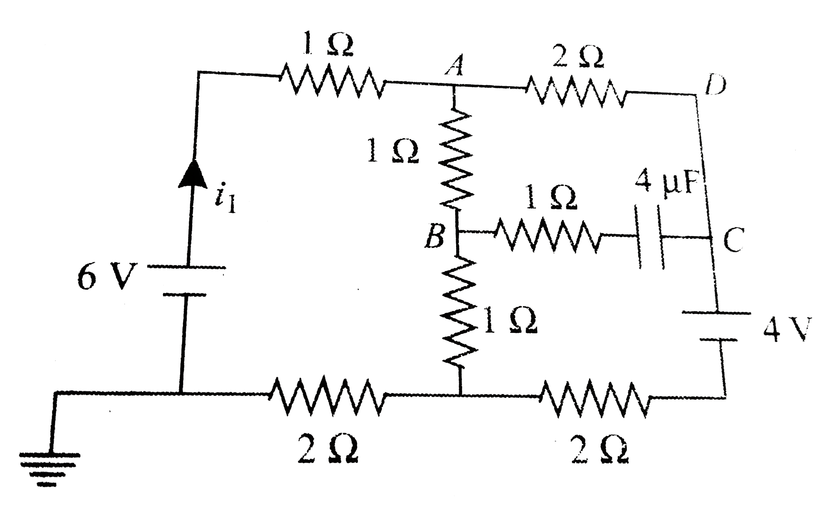
The charge in capacitor is
View SolutionIn the netwrok shown in fig. each resistance is R.
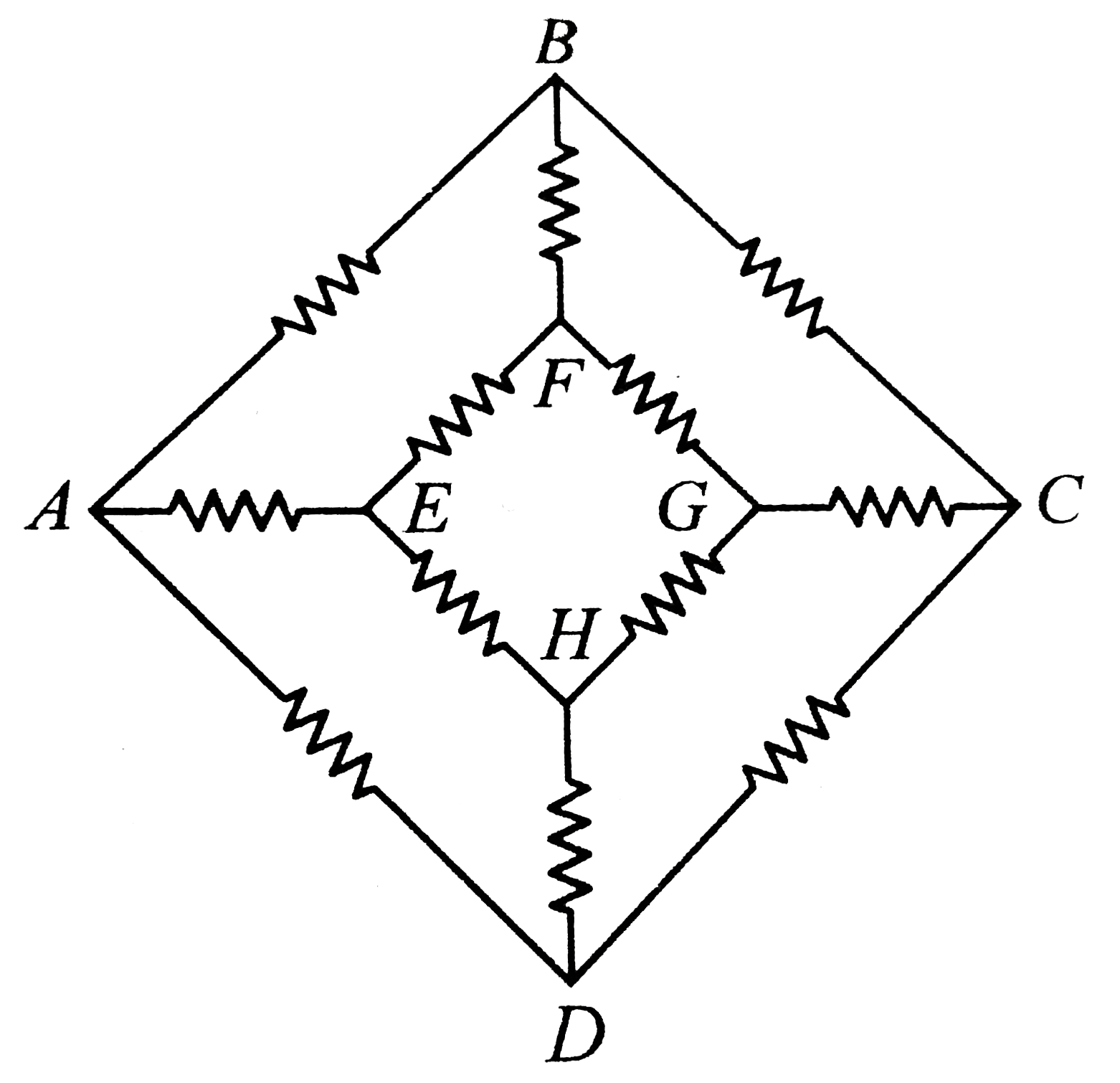
The equivalent resistance between A and B is
View SolutionIn the netwrok shown in fig. each resistance is R.
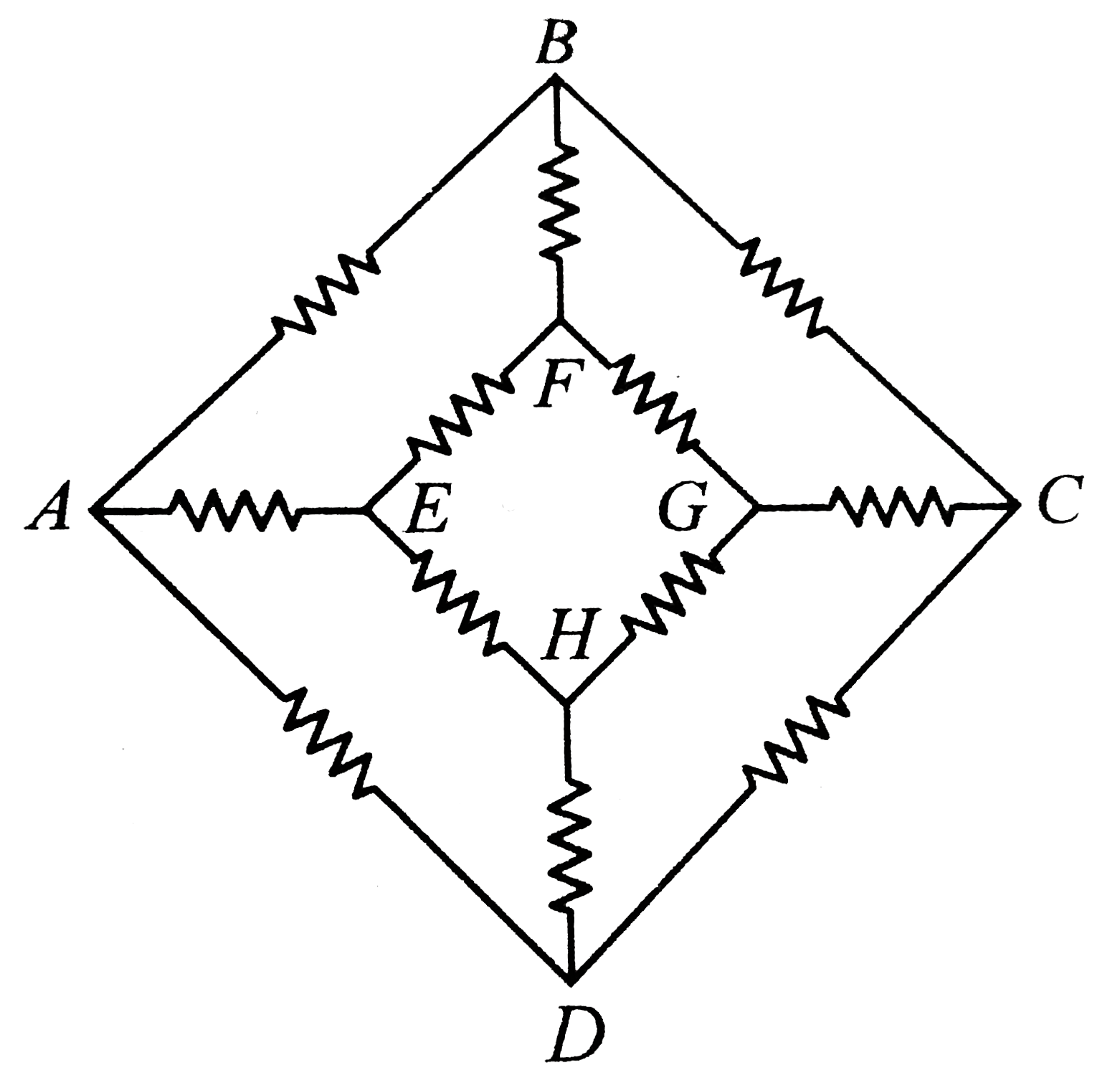
The equivalent resistance between A and G is
View SolutionIn the netwrok shown in fig. each resistance is R.
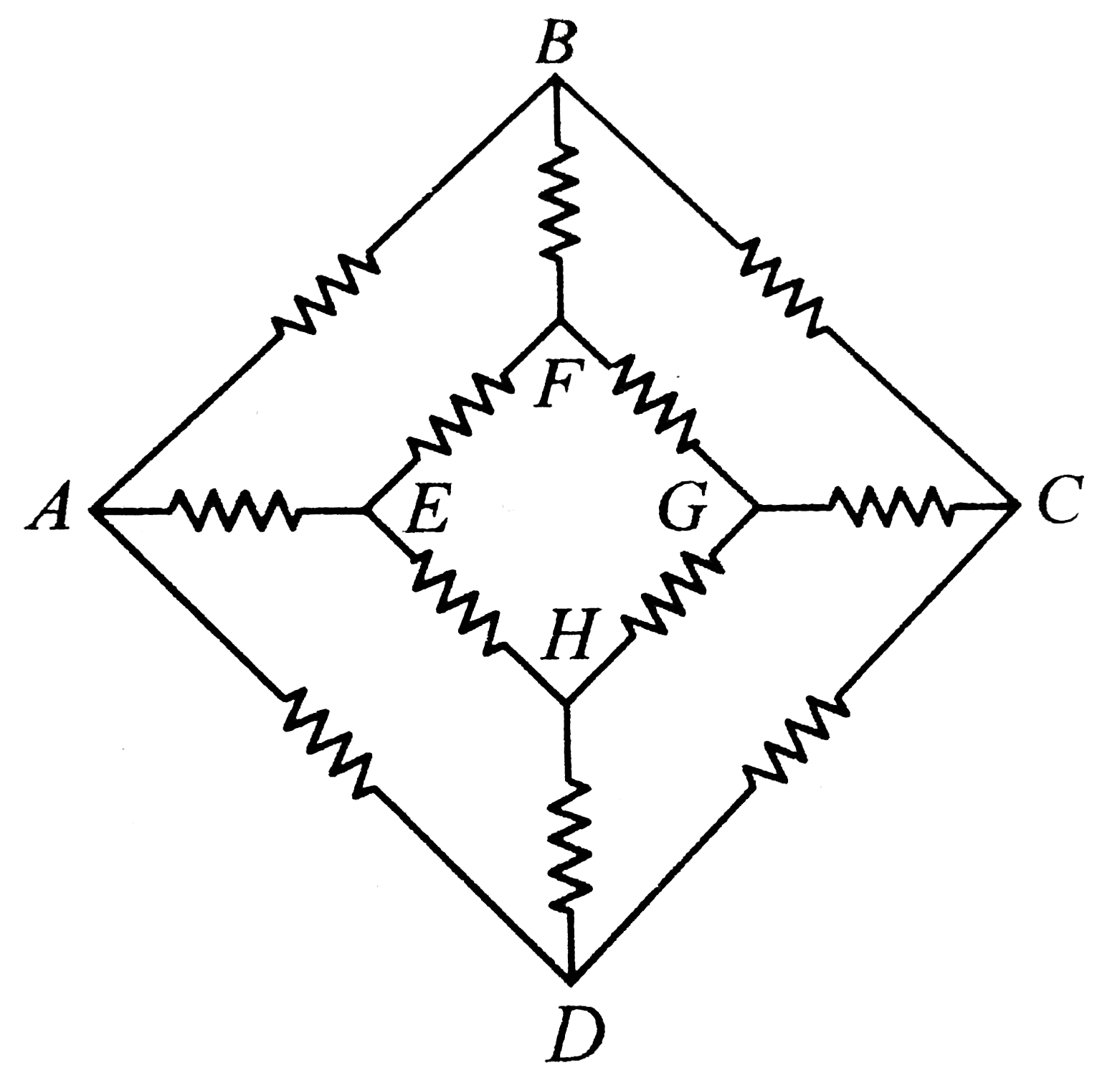
The equivalent resistance between A and C is
View SolutionA resistor circuit is constructed such that 12 resistor are arranged to form a cube as shown in fig. Each resistor has a resistance of `2Omega.` The potential difference of 30V is applied across two of the opposing points as shown
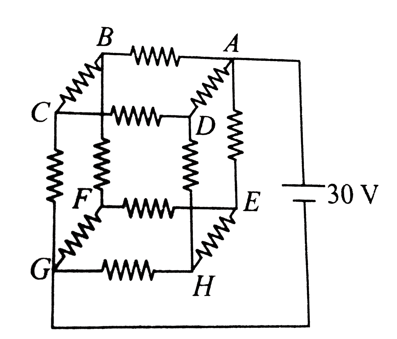
The points having the same potential are
i. B,D,E ,ii. C,F,H ,iii. C,E
View SolutionA resistor circuit is constructed such that 12 resistor are arranged to form a cube as shown in fig. Each resistor has a resistance of `2Omega.` The potential difference of 30V is applied across two of the opposing points as shown
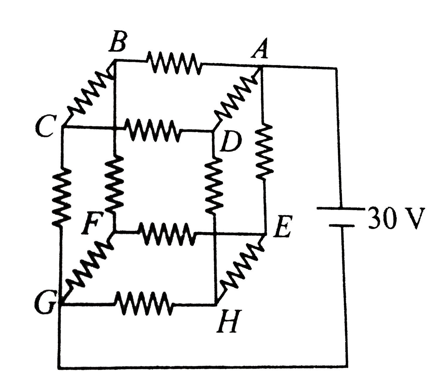
If we replace resistor between A and B and resistors between G and H by wires of zero resistance, then the points having the same potential are
i. D,E,C,F ,ii. A,B ,iii. G,H
View SolutionA resistor circuit is constructed such that 12 resistor are arranged to form a cube as shown in fig. Each resistor has a resistance of `2Omega.` The potential difference of 30V is applied across two of the opposing points as shown
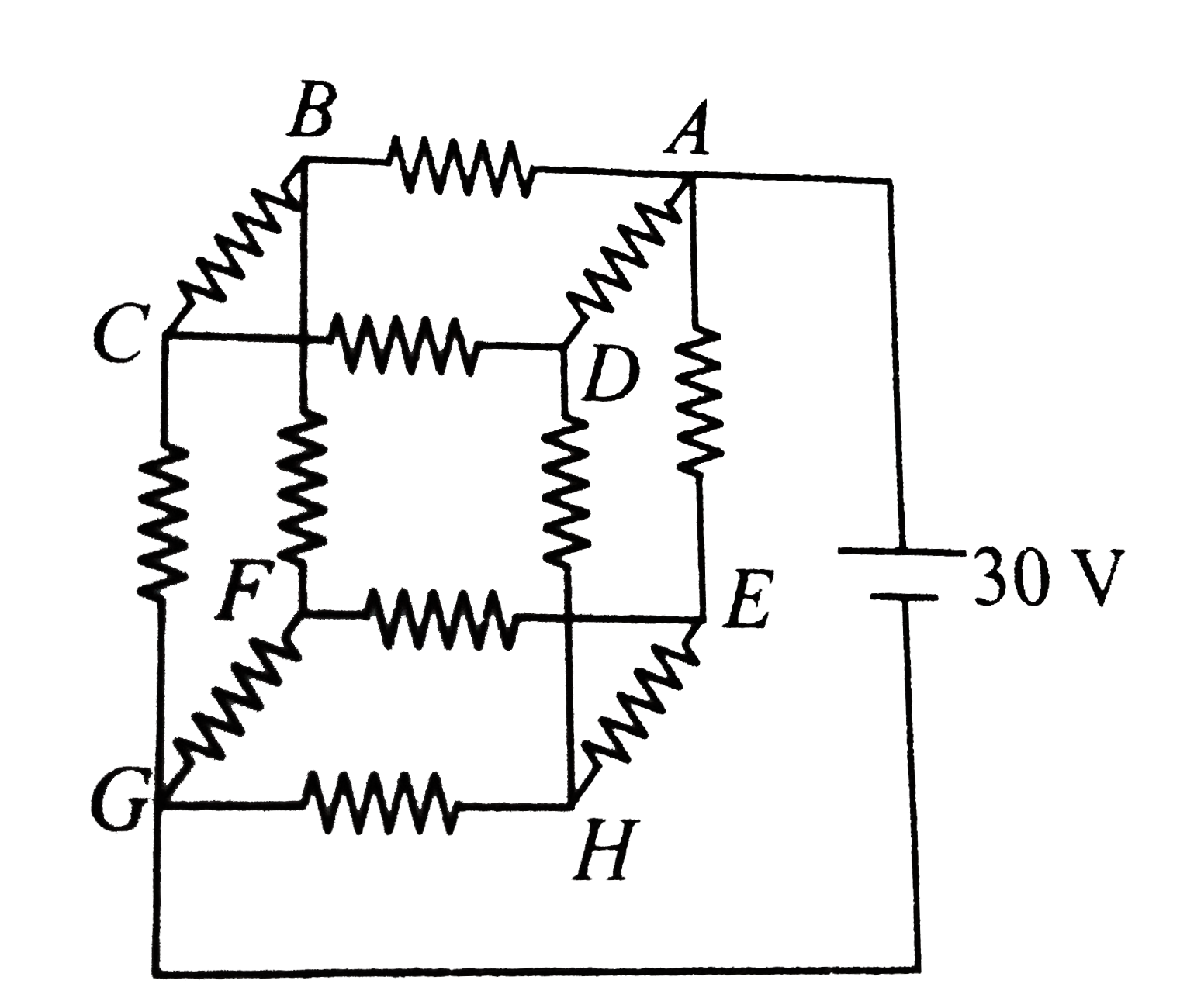
In question 20, the potential difference between the points C and G is
View SolutionConsider 12 resistor arranged symmetrically in shape of bipyraimd ABCDEF. Here ABCD is a square. Point E, point F, and centre of square are in the same straight line perpendicular to the planw of squar. The resistacne of each resistor is R.
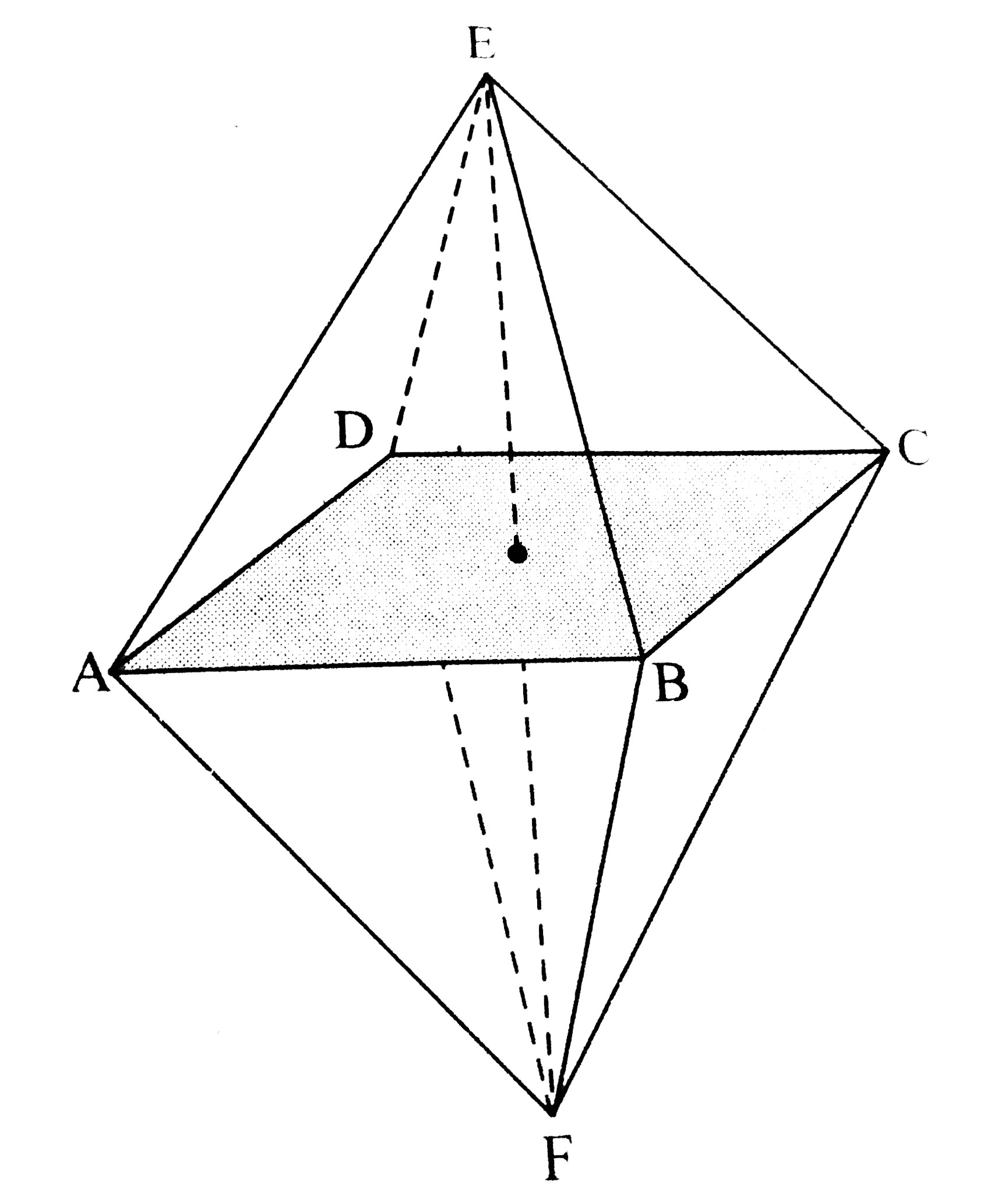
The effective resistance between E and F is
View SolutionConsider 12 resistor arranged symmetrically in shape of bipyraimd ABCDEF. Here ABCD is a square. Point E, point F, and centre of square are in the same straight line perpendicular to the planw of squar. The resistacne of each resistor is R.
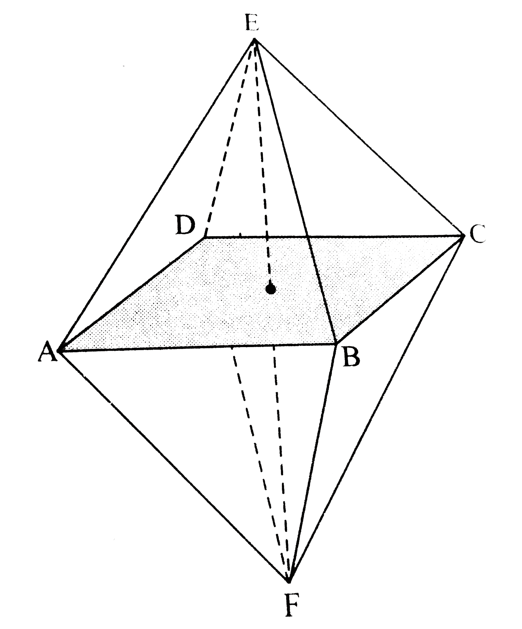
The effective resistance between A and C is
View SolutionConsider 12 resistor arranged symmetrically in shape of bipyraimd ABCDEF. Here ABCD is a square. Point E, point F, and centre of square are in the same straight line perpendicular to the planw of squar. The resistacne of each resistor is R.
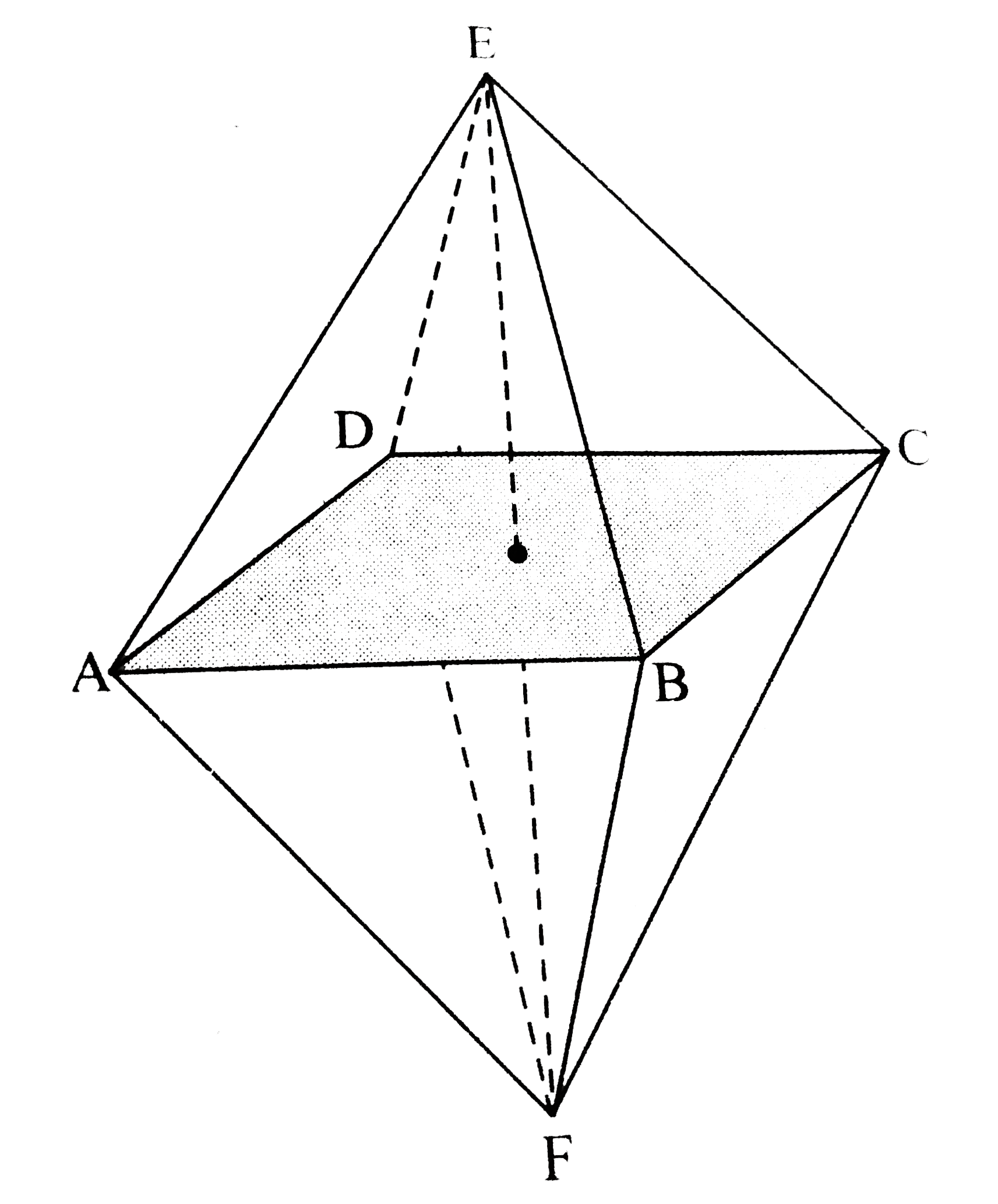
The effective resistance between A and B is
View Solutionshown a network of four resistance and three batteries
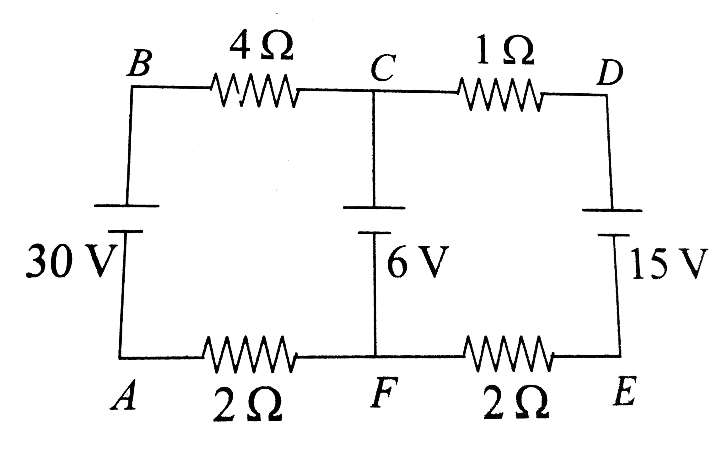
Choose the correct alternative.
View Solutionshown a network of four resistance and three batteries
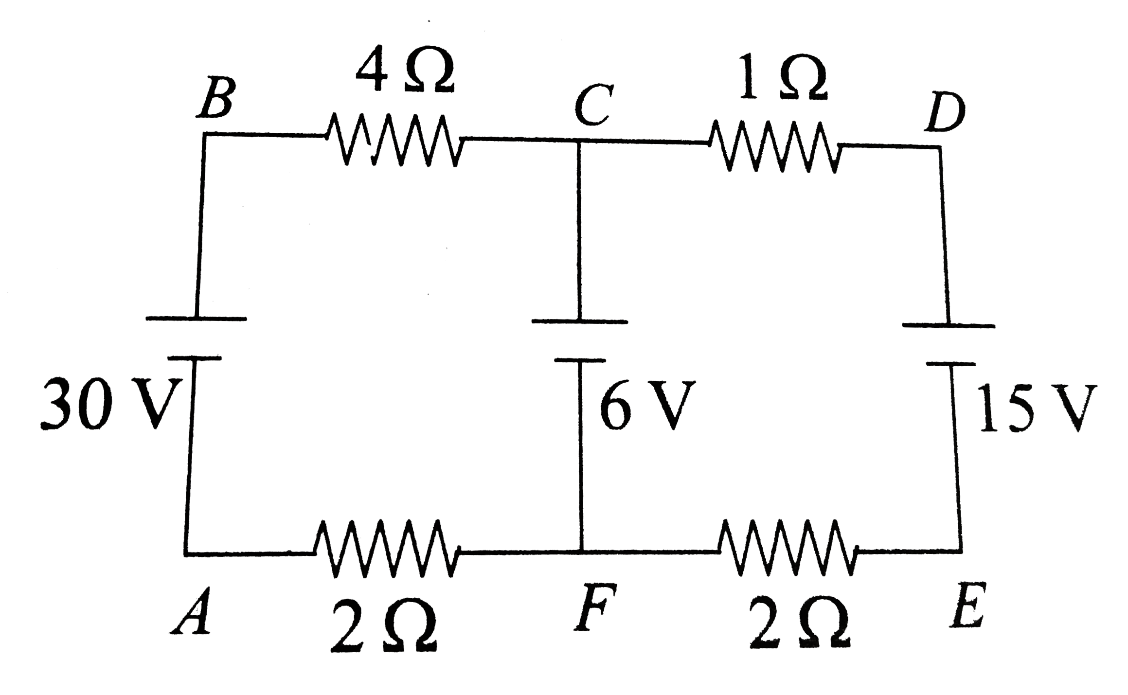
Mark the incorrect statement.
View Solutionshown a network of four resistance and three batteries
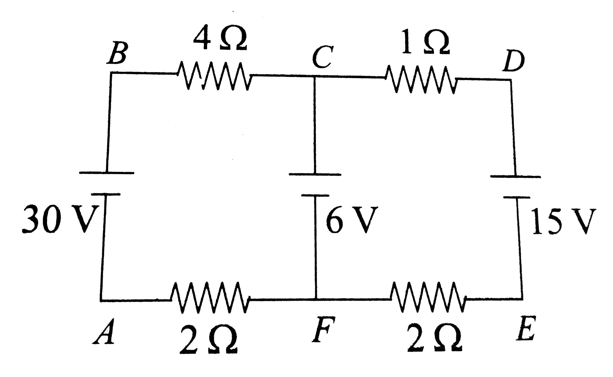
Which of the batteries is getting charged.
View SolutionIn the arrangement, 11 wires each of resistance `5Omega` are used as sides of cube. A potential difference of 70 V is maintained between corners A and B of cube.
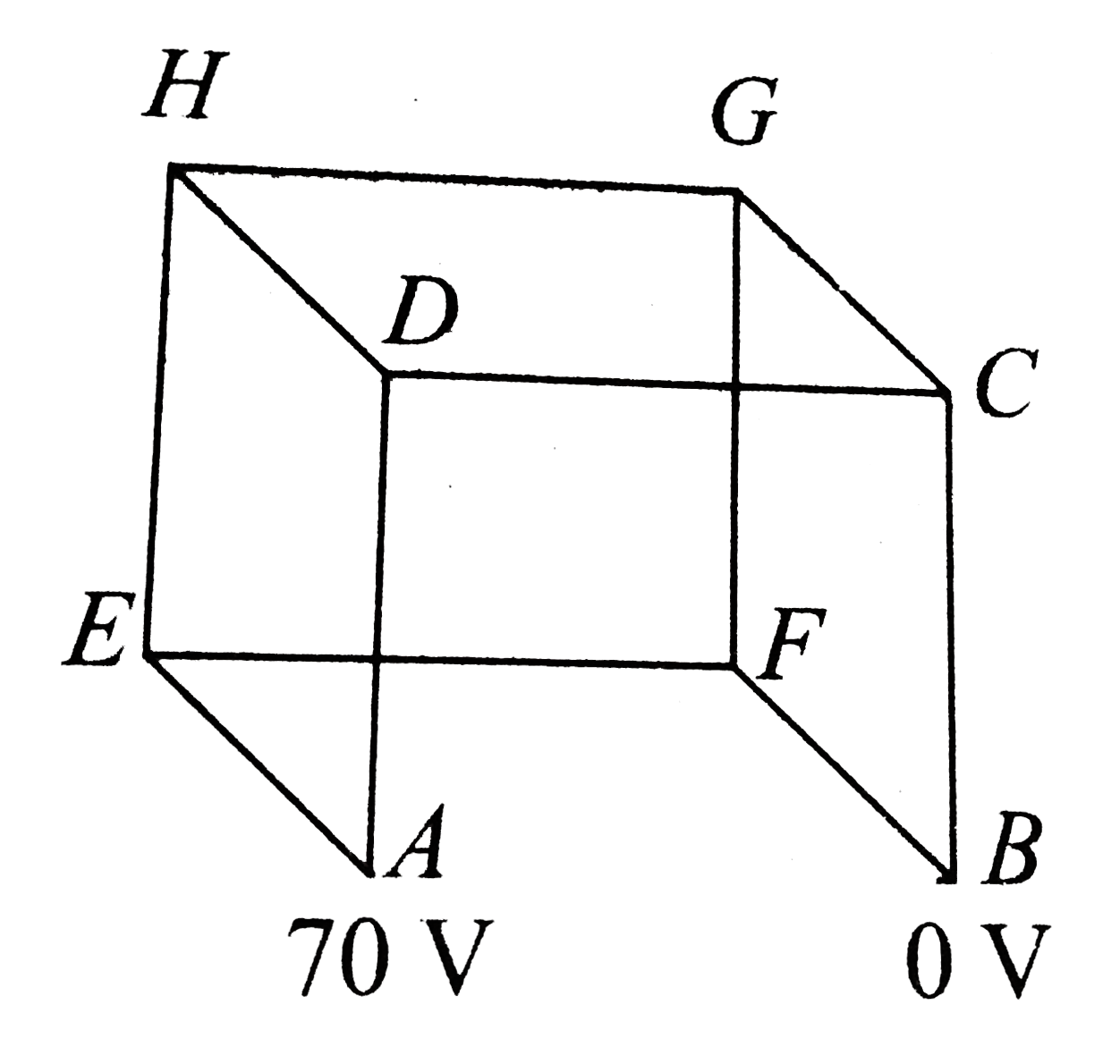
Current flowing in wire HG is
View SolutionIn the arrangement, 11 wires each of resistance `5Omega` are used as sides of cube. A potential difference of 70 V is maintained between corners A and B of cube.
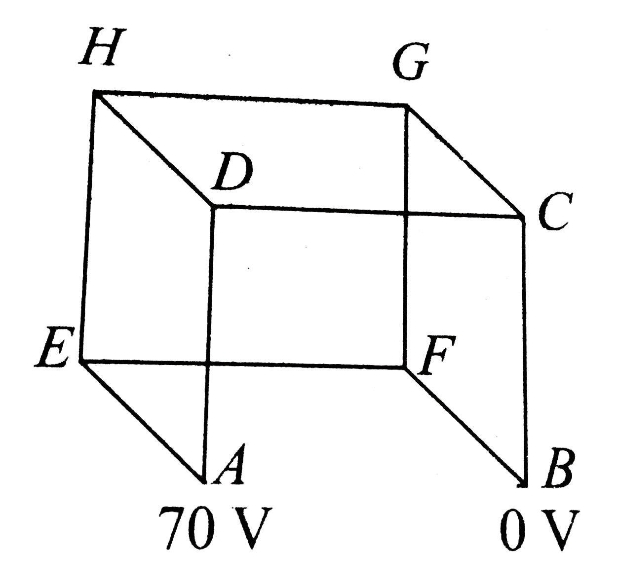
Current flowing in wire Ef is
View SolutionIn the arrangement, 11 wires each of resistance `5Omega` are used as sides of cube. A potential difference of 70 V is maintained between corners A and B of cube.
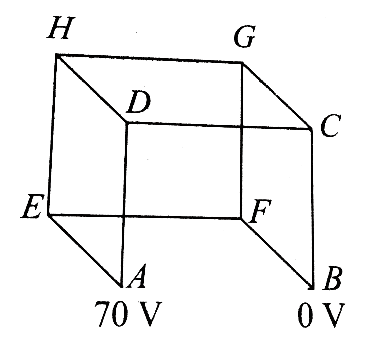
Potential of junciton G is
View SolutionConsider the circuit shown in fig.
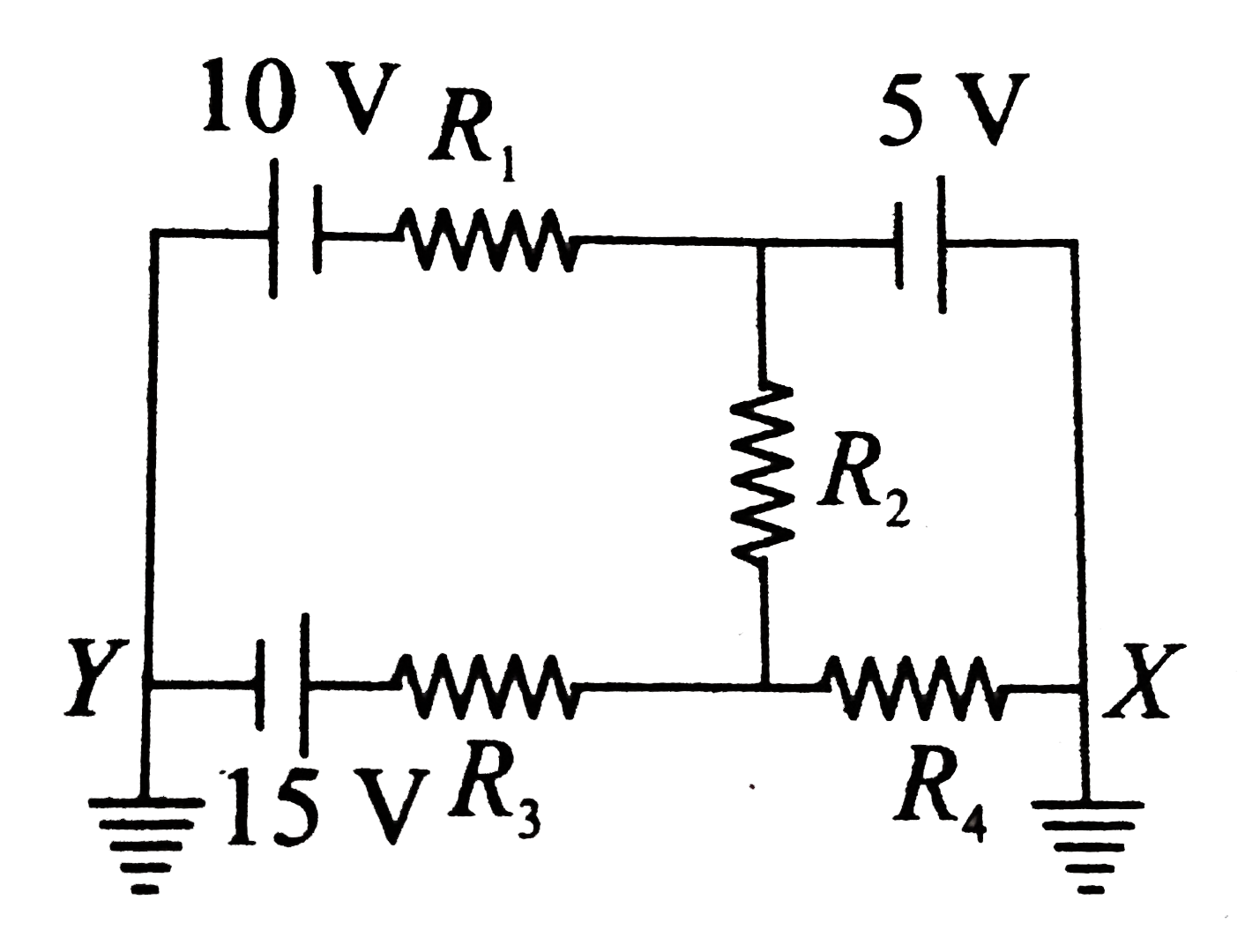
Current through `R_2` is zero if `R_4 = 2Omega and R_3 = 4 Omega` in this case
View SolutionConsider the circuit shown in fig.
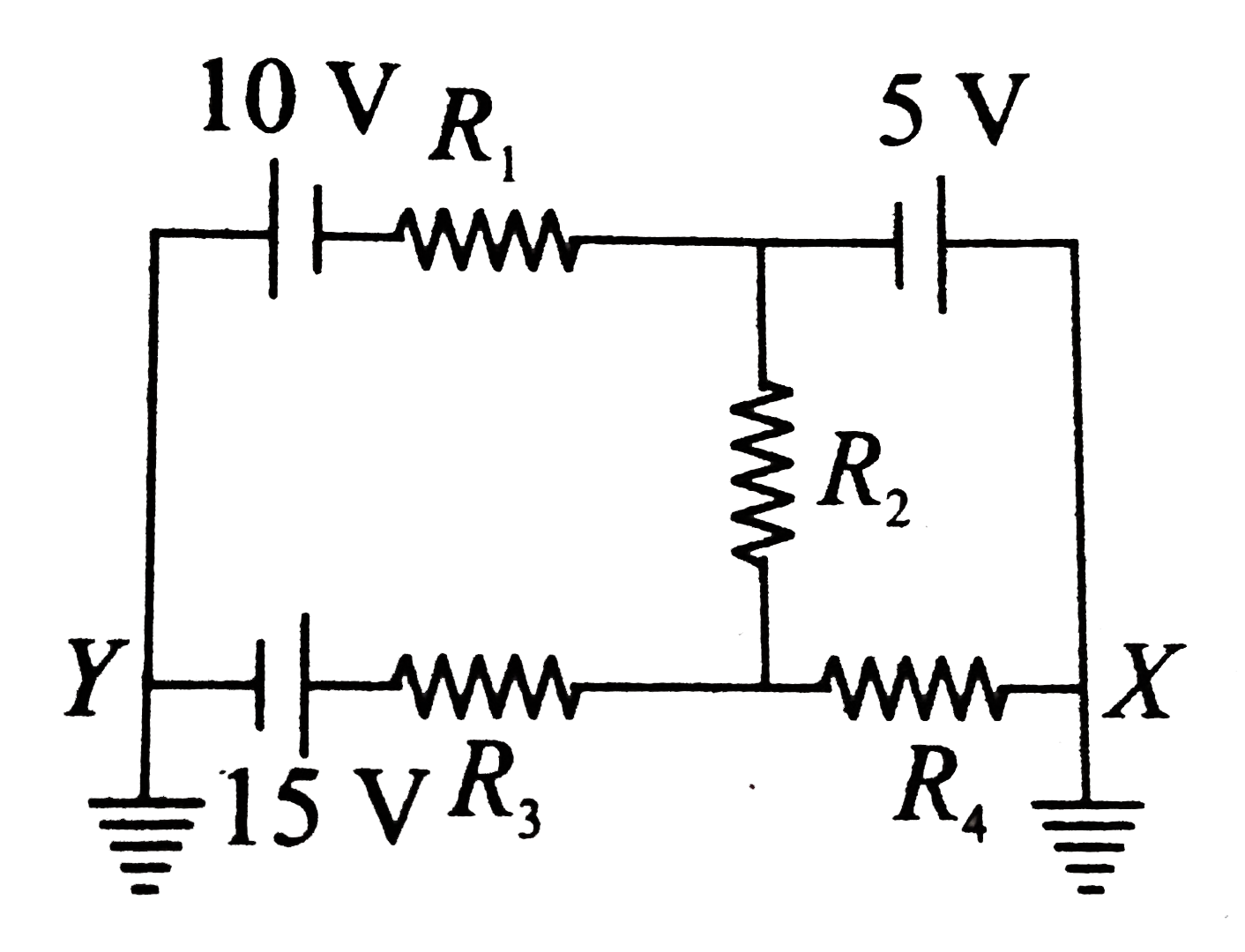
Assuming `R_1 = 2Omega,` current passing through resistance `R_1` is
View SolutionConsider the circuit shown in fig.
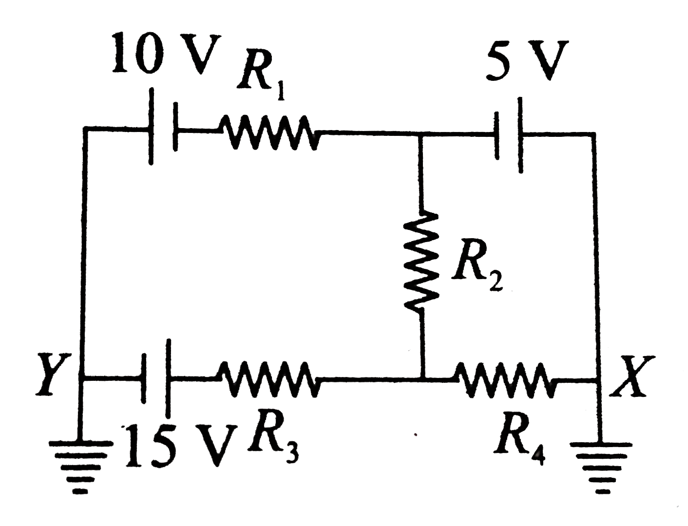
Assuming `R_1 =2Omega = R_4, R_3 = 4Omega,` current passing through the circuit if resistance `R_2` is removed is (remove ground connection at point X)
View SolutionThe following two questions refer to the circuit shown. Assume that the capacitors are initially uncharged.
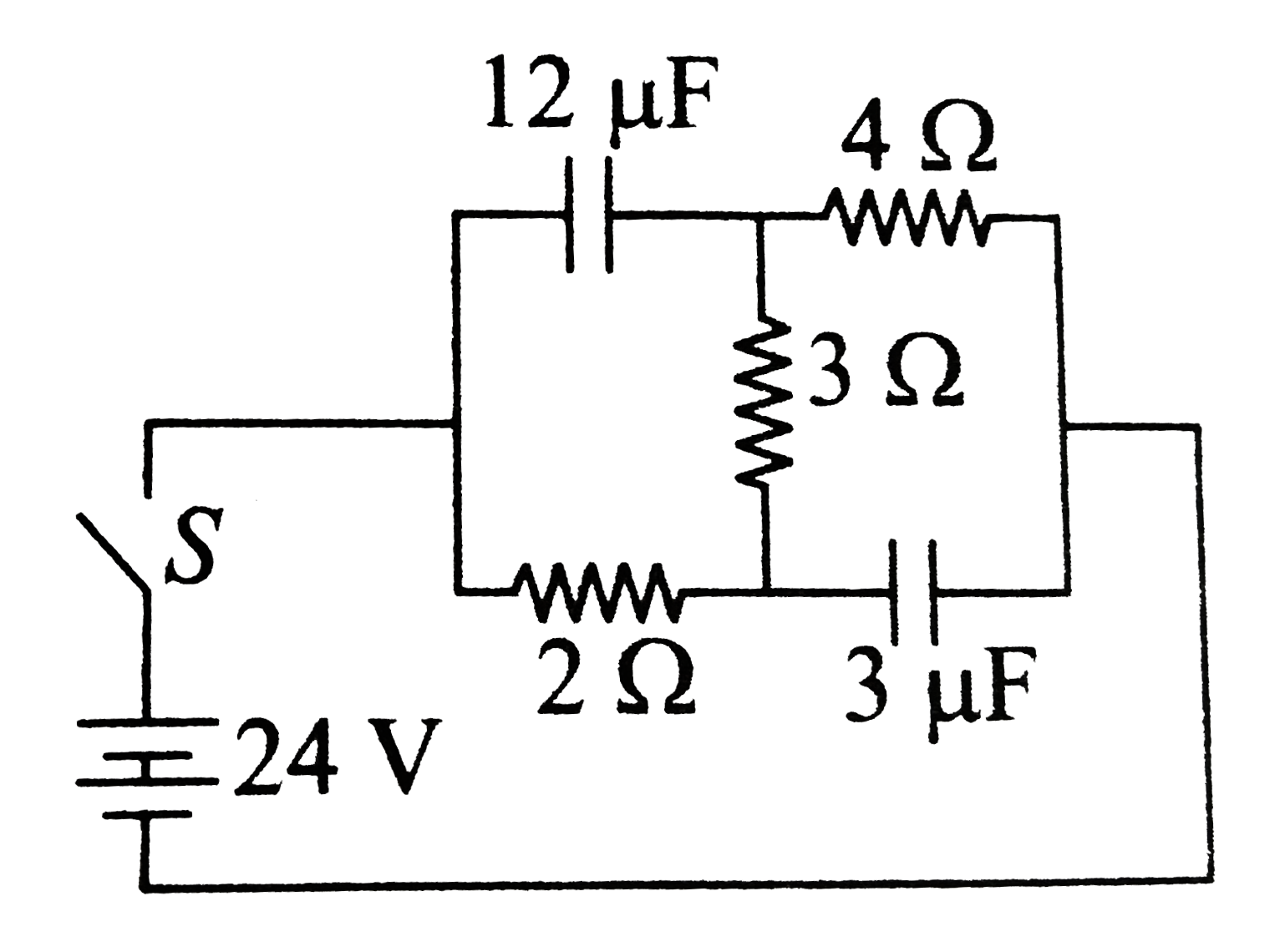
At time t = 0, the switch S in the circuit is closed. At that instant, what is the equivalent resistance of the circuit?
View SolutionThe following two questions refer to the circuit shown. Assume that the capacitors are initially uncharged.
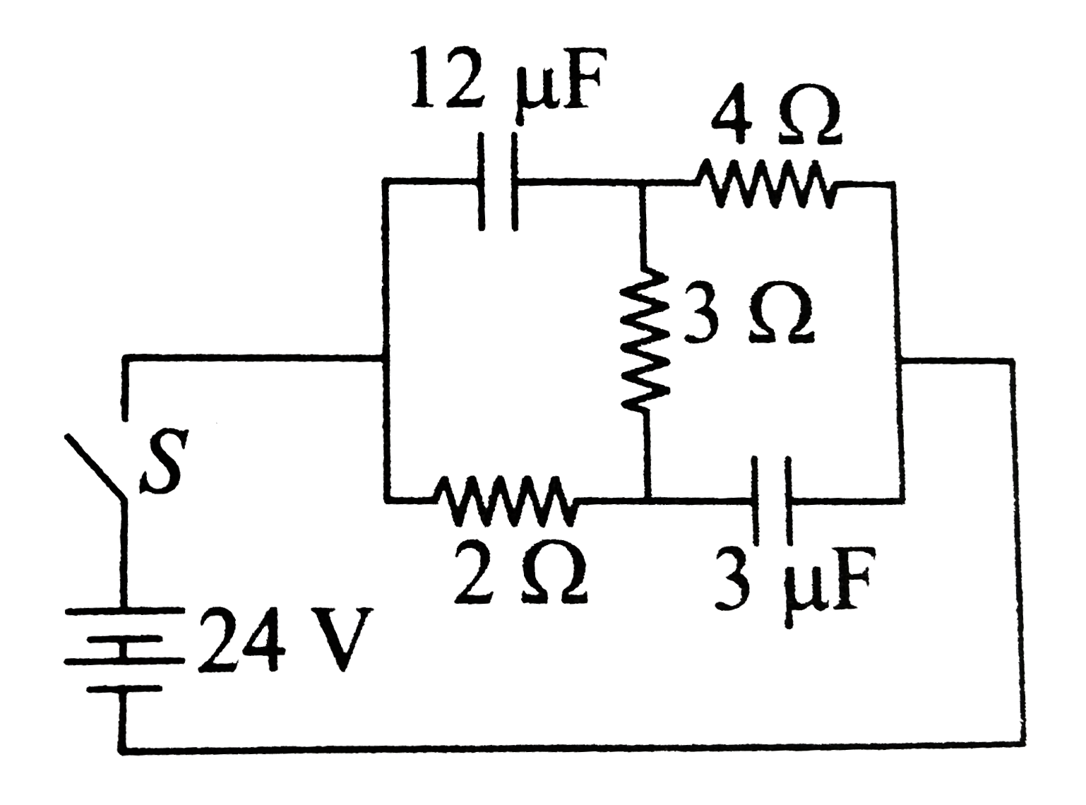
After the switch has been closed for a long time, how much charge is on the positive plate of the `3muF` capacitor?
View Solution
Comprehension questions and complete solutions for chapter ELECTRIC CURRENT AND CIRCUIT of CENGAGE PHYSICS (HINGLISH) of Class 12