Complete Solutions to Illustration of chapter ELECTRIC CURRENT AND CIRCUIT of Class 12 book with complete answers and questions
| Class 12 | PHYSICS |
| Chapter | ELECTRIC CURRENT AND CIRCUIT |
| CENGAGE PHYSICS | Illustration |
| Number Of Questions | 74 |
| Academic Year | 2023-24 |
A given wire is stretched to double its length. How will its resistance change ?
View SolutionThe wire is stretched to increase the length by 1%. Find the percentage change in the resistance.
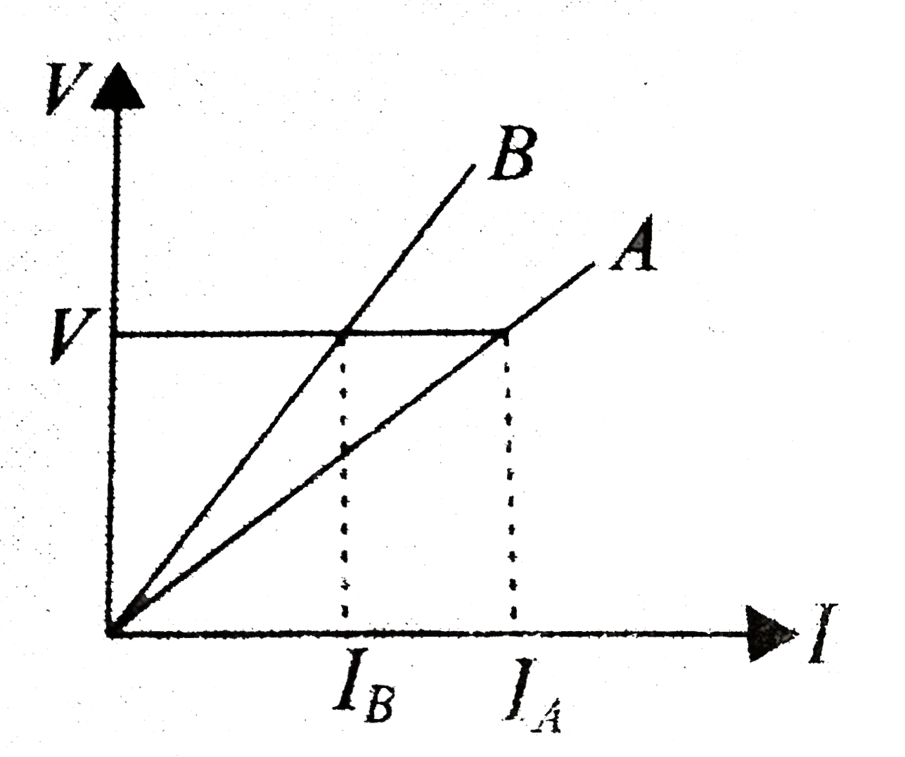
View SolutionThe voltage-current graphs for two resistor of the same material and the same radius with lengths, `L_1 and L_2` are shown in fig 5.2. if `L_1 gt L_2`, state with reason which of these graphs represents voltage- current change of `L_1.`
View SolutionIn a hydrogen discharge tube, the number of protons drifitin across a cross section per second is `1.0xx10^(18)`, while the number of electrons drifting in the opposite direction across the same cross section is `2.7xx 10^(18)` per second. Find the curernt flowing in the tube.
View SolutionYou need to produce a set of cylindrical copper wires 2.5 m long that will have a resistance of `0.125Omega` each. What will be the mass of each of these wires? (Density of copper is `8.9xx10^3 kgm^(-3)` and resistivity of copper is `1.72 xx10^(-8) Omegam).`
View SolutionConsider a wire of length l, area of cross section A, and resistivity `rho` with resistance `10 Omega`. Its length is increased by applying a force, and it becomes four times of its original value. Find the changed resistance of the wire.
View SolutionA wire of mass m length I, density d, and area of cross section A is stretched in such a way that is length increases by 10% of its original value, Expresss the changed resistance in percentage.
View SolutionA uniform copper wire of mass `2.23 xx10^(-3)` kg carries a current of 1 A when 1.7 V is applied across it. Calculate the length and the area of cross section, if the wire is uniformaly stretched to double its length, calculate the new resistance. Density of copper is `8.92xx10^3 kgm^(-3)` and resistivity is `1.7xx10^(-8) Omega m.`
View SolutionA copper wire has a square cross section of 6 mm on a side. The wire is 10 m long and carries a current of 3.6A. The density of free electrons id `8.5x10^(28)//m^3.`Find the magnitude of (a) the current density in the wire , (b) the electric field in the wire. (c ) How much time is required for an electron to travel the length of the wire? `("rh, electrical resistivity, is" 1.72 xx10^(-8) Omegam.)`
View SolutionConsider a wire of length 0.1 m with an area fo cross section `1 mm^2` connected to 5V. Find the current flowing through the metallic wire where `mu = 5xx10^(-6) m^2`
`V_1 s^(-1), e = 1.6xx10^(-19) C, and n = 8xx10^(28) m^(-3).`
View Solution(a) Estimate the average drift speed of conductin electrons in a copper wire of cross sectional area `1.0xx10^(-7) m^2` carrying a current of 1.5 A. Assume that each copper atom contributes roughly one conduction electron. The density of copper is `9.0xx10^3 kgm^(-3)` and its atomic mass is `63.5 u.` (b) Compare the drift speed obtained with the speed of propagation of electric field along the conductor, which causes the drift motion.
View SolutionFind the approximate total distance traveled by an electron in the time interval in which its displacement in one meter along the wire.
View SolutionFind the total linear momentum of the electrons in a conductor of length `I = 1000m` carrying a current I = 70A.
View SolutionHow much time will be taken by an electron to move distance I = 1km in a copper wire of cross section `A = 1mm^2` if it carries a current I = 4.5A?`
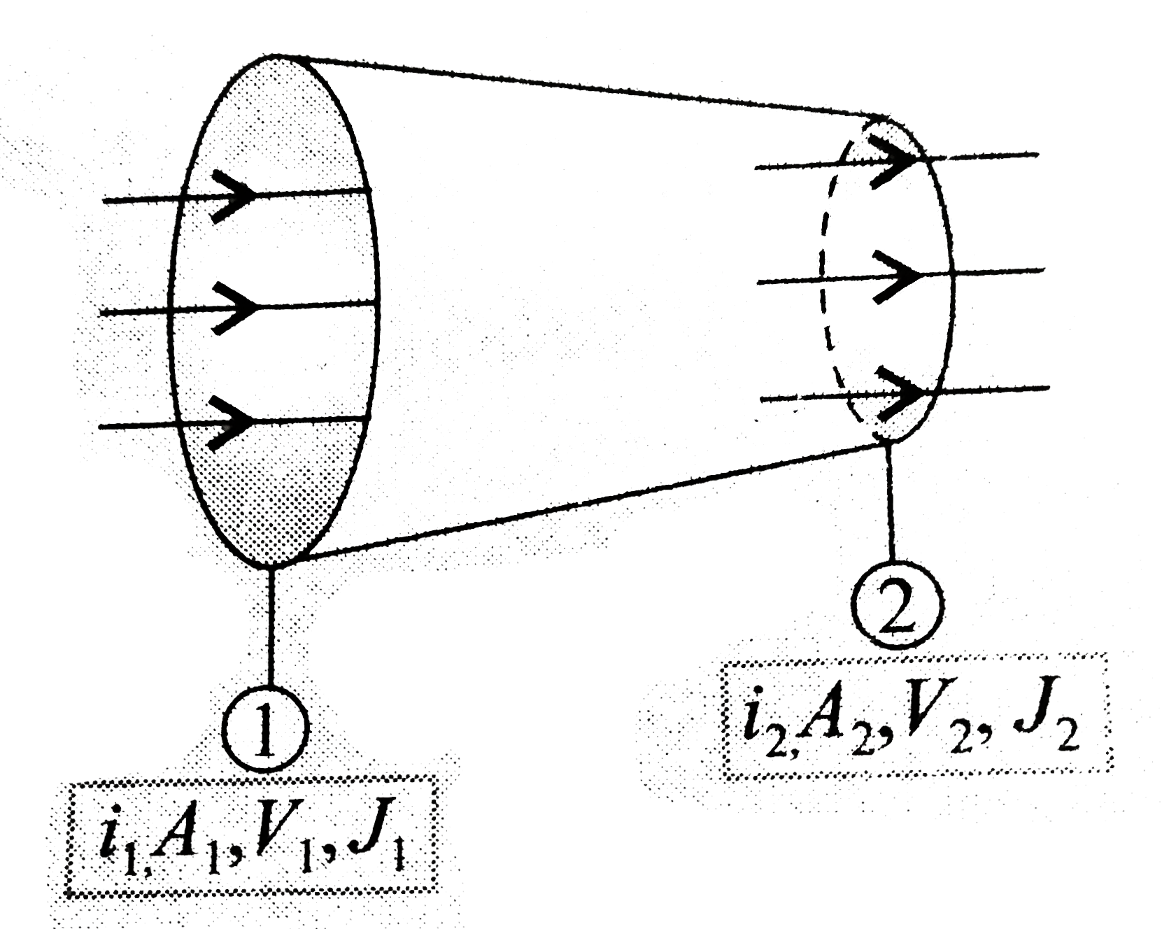
View SolutionCurrent is flowing from a conductor si nonuniform cross sectional area. If `A_1 gt A_2,` then find relation between
a. `i_1 and i_2`
b. `j_1 and j_2`
c. `(v_d)_1 and (v_d)_2`
(drift velocity) where I is current, j is current density, and V is drift velocity.
View SolutionA copper wire fo cross-sectional area `3.00xx10^(-6) m^2` carries a current 10.0A.
a. Find the drift speed of the electrons in the wire. Assume that each copper atom contributes one free electron to the body of material.
b. Find the average time between collisions for electrons in the copper at `20^@C.` The density of copper si `8.95 gcm^(-1)`, molar mass of copper is `63.5 gmol^(-1)`, Avogadro number is `6.02x10^(23)` electrons per mol and resistivity of copper is 1.7 xx10^(-8) Omegam.`
View SolutionConsider a conductor of length 40 cm where a potential difference of 10V is maintained between the ends of the conductor. Find the mobility of the electrons provided the drift velocity of the electrons is `5xx10^(-6) ms^(-1)`
View SolutionA copper coil has resistance of `20.0 Omega at 0^@C` and a resistance of `26.4 Omega at 80^@C`. Find the temperature coefficient of resistance of copper.
View SolutionA metallic wier has a resistance of `120 Omega at 20^@C.` Find the temperature at which the resistance of same metallic wire rises ot `240 Omega` where the teperature coefficient of the wire is `2xx10^(-40) C^(-1).`
View SolutionA resistance R of therimal coefficient of resistivity `alpha` is connected in parallel with a resistance 3R. Having thermal coeffiecinet of resistivity `2alpha` Find the value of `alpha_(eff)`
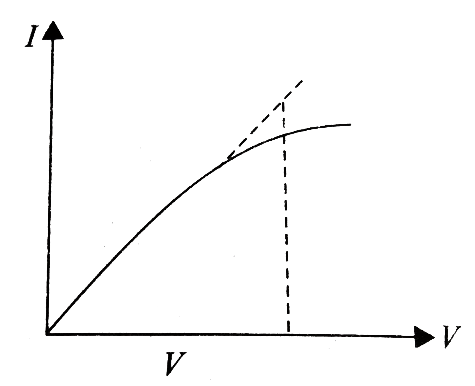
View SolutionThe I-V characteristics of a resistor is observed to deviate from a straight line for higher value of current as shown in fin 5.17 why?
View SolutionA car has a fresh storage battery of emt `12 V` and internal resistance `5.0 xx 10^(-2) Omega`. If the starter moter the battery when the starter is on?
(b) After long use, the internal resistance of the storange battery increase to `500 Omega`. What maximum current can be drawn from the battery? Assume the emt of the battery to remain unchanged.
(c) If the discharged battery is changed by an external emf source, is the terminal voltage of the battery during changing greater of less than is emf `12 V`?
View SolutionThe V - I graphs for two resistors and their series combination are shown in Fig 5.23. Which one of these graphs represents the series combination of the two resistors? Given reason for your answer.
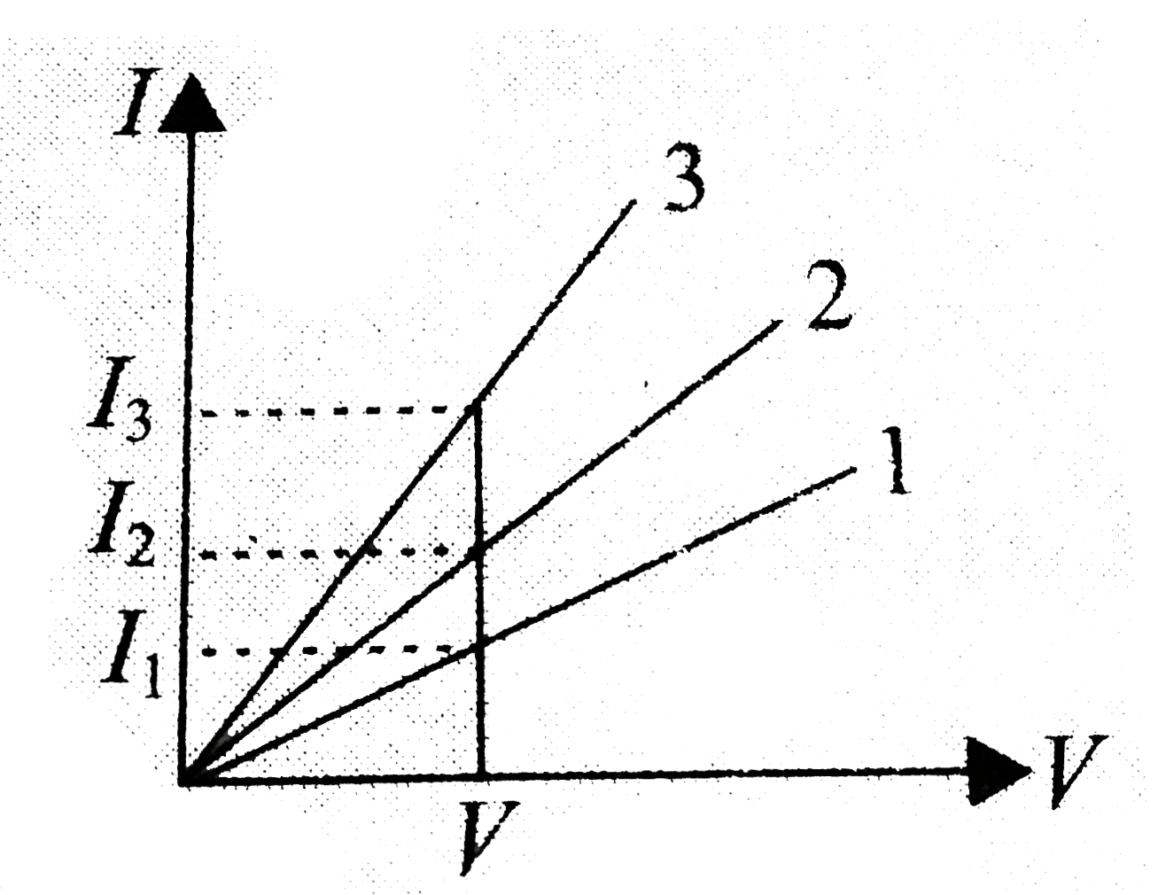
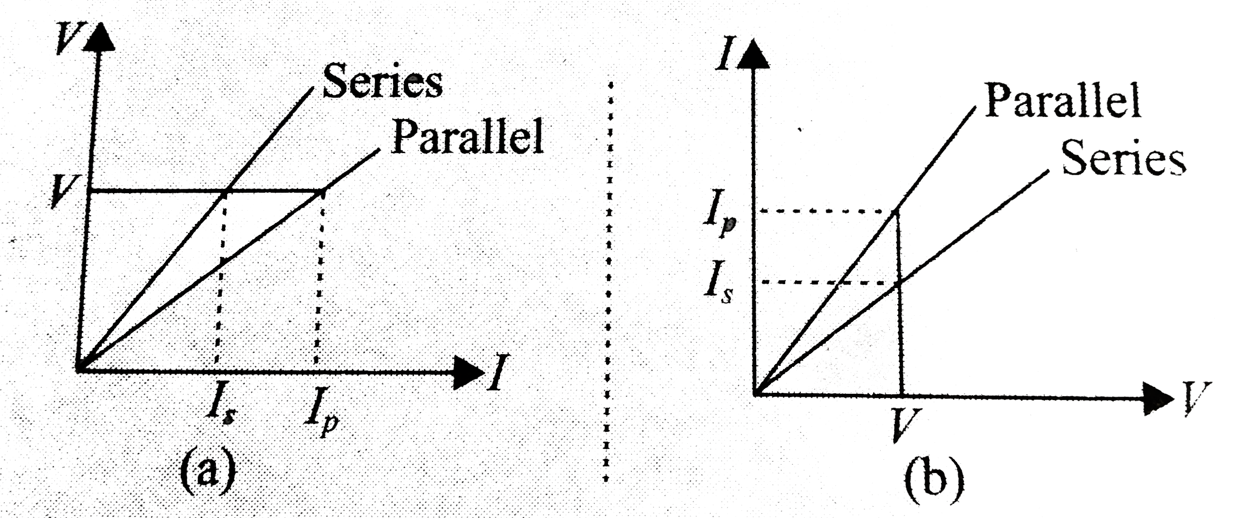
View SolutionTwo students perform experiments on series and parallel combinations of two given resistors `R_1 and R_1` and plot the following V -1 graphs [Fig. 5.24.]. Which of the graphs is/are correctly labeled in terms of the words 'series' and 'parallel'? Justify your answer.
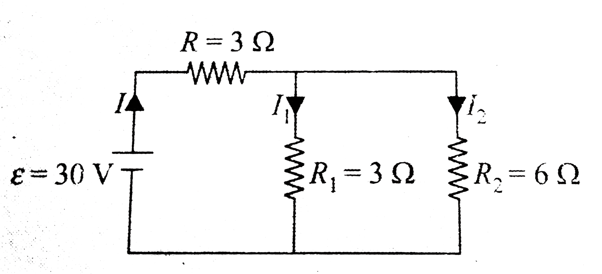
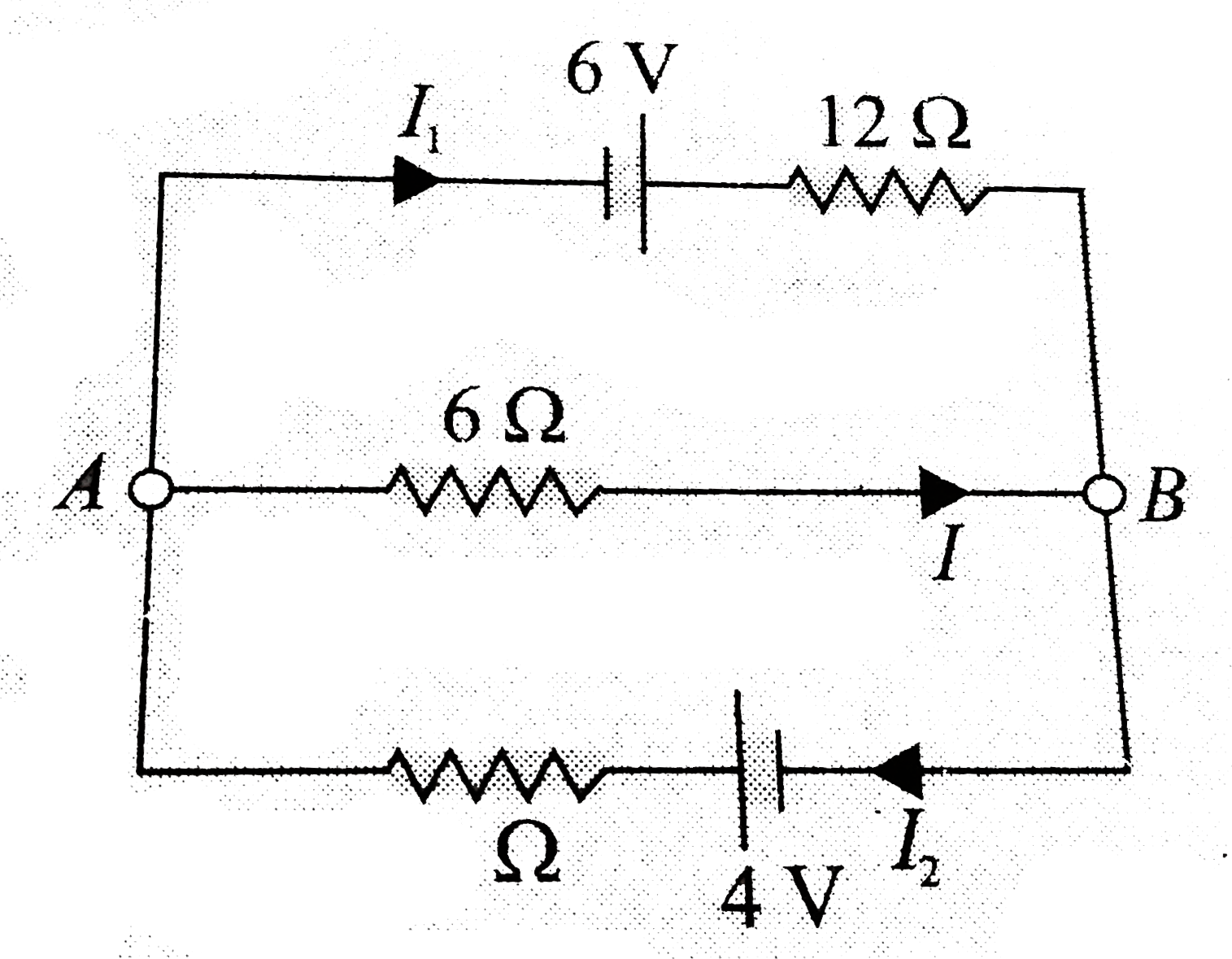
View SolutionIn the circuit given, find the currents `I`, `I_1` and `I_2` in the circuit.
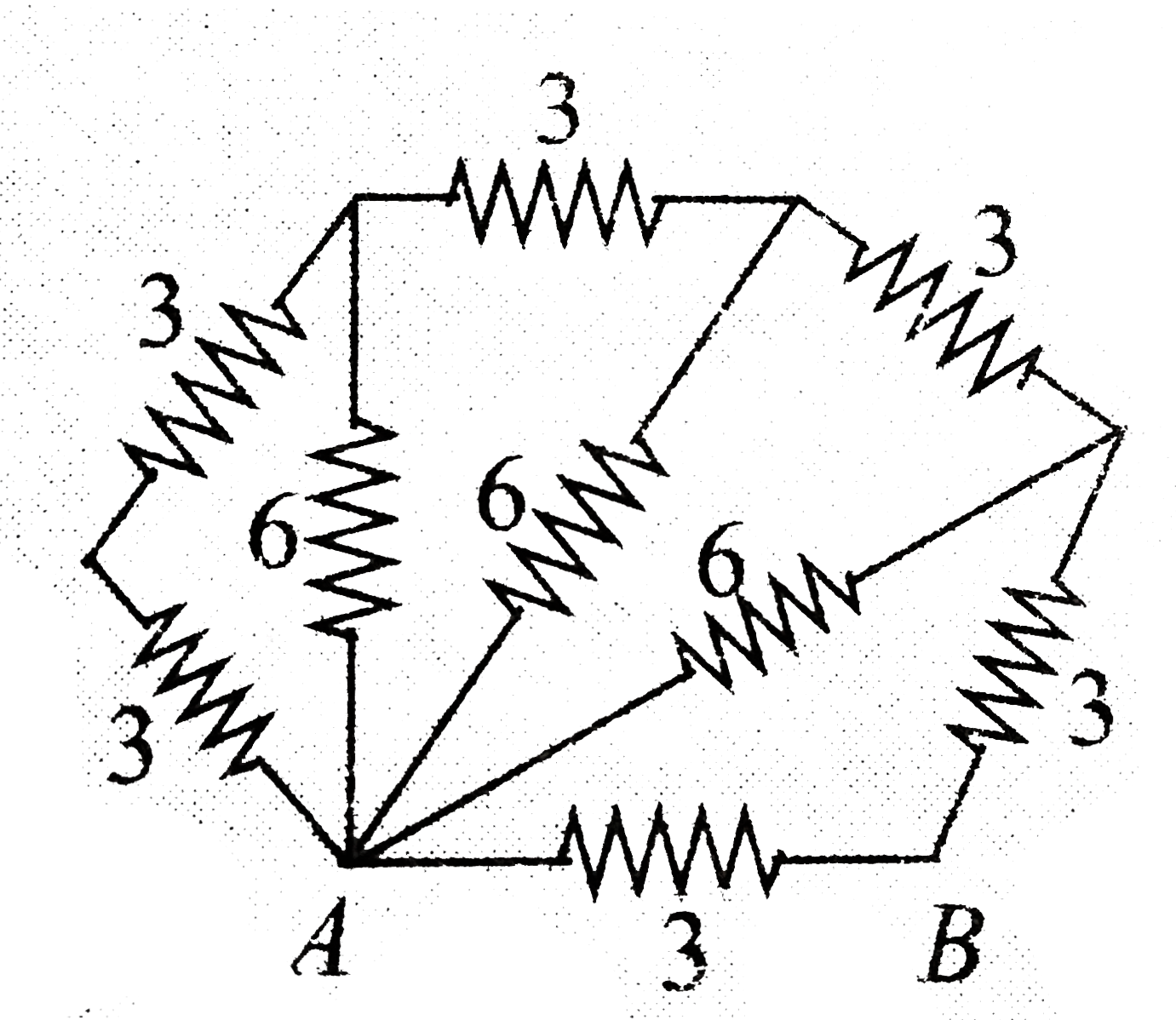
View SolutionAll resistances in fig. 5.34 are in ohm. Find the effective resistance (in `Omega`) between points A and B.
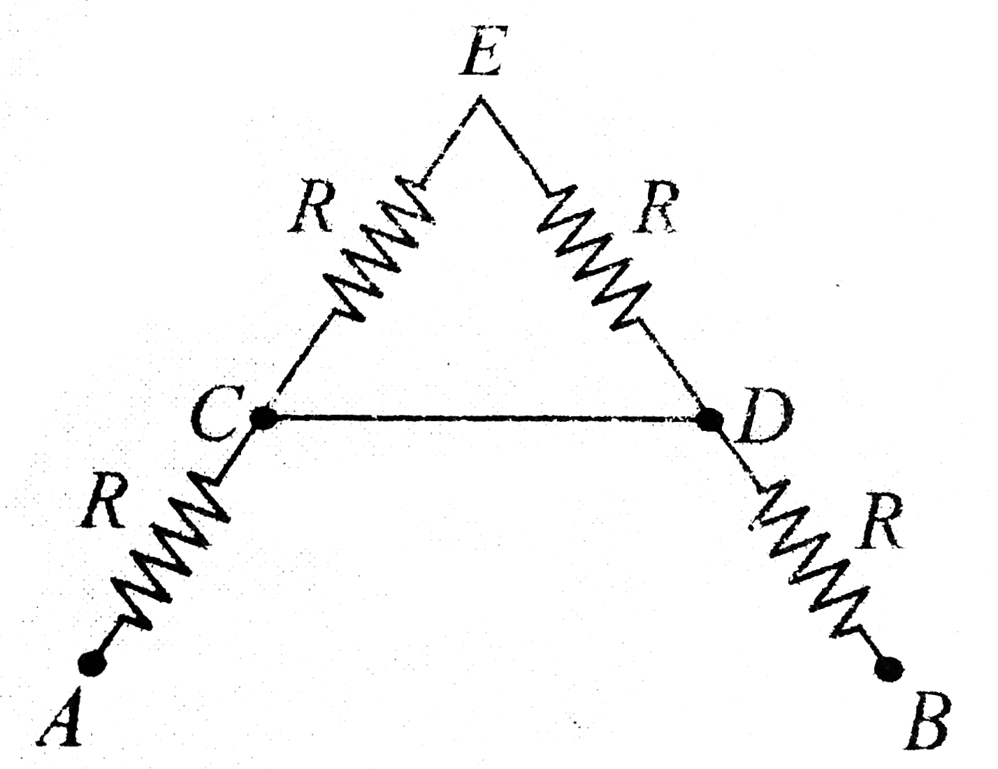
View SolutionFour identical resistances each having value R are arranged as shown in Figure. Find the equivalent resistance between A and B.
View SolutionFind the `R_(AB)` in the given network.

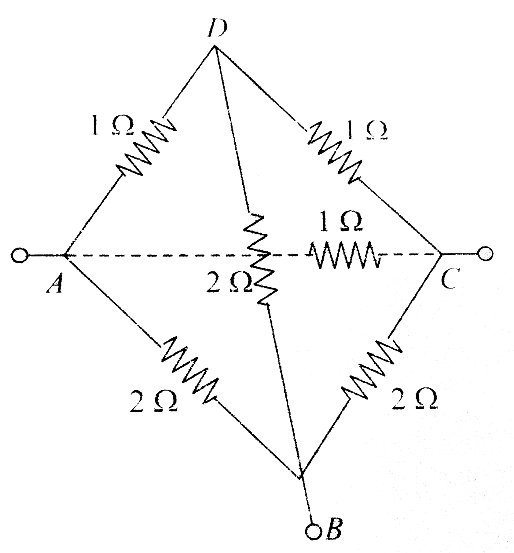
View SolutionSix resistor are arranged along the edges of a pyramid as shown in Fig. 5.43. The values of resistances are mentioned with resistances in the figure. Find the effective between A and B.
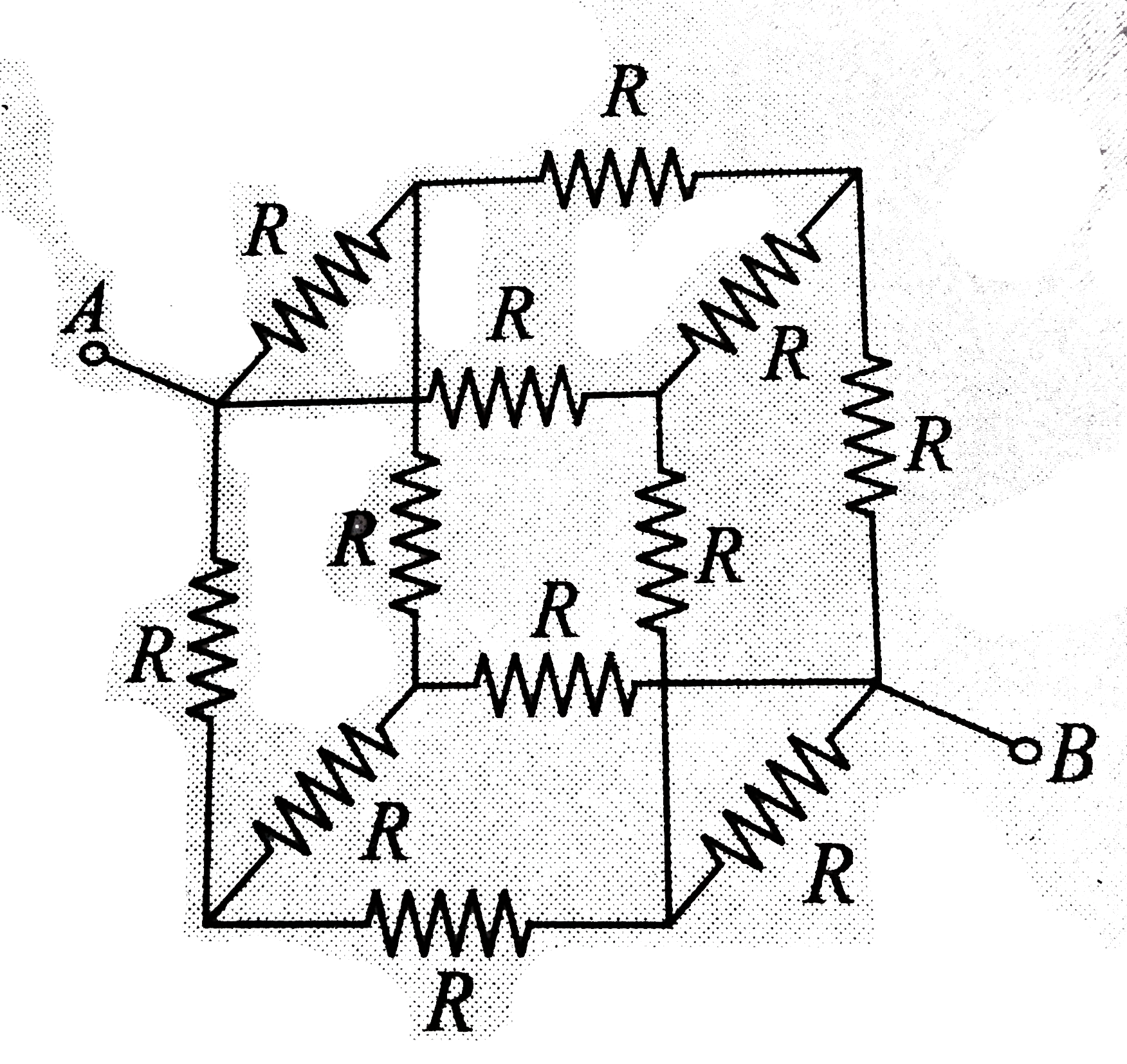
View SolutionTwelve identical resistances arranged on all edges of a cube. The resistors are all the same. Then find the equivalent resistance between the edges A and B as shown in.
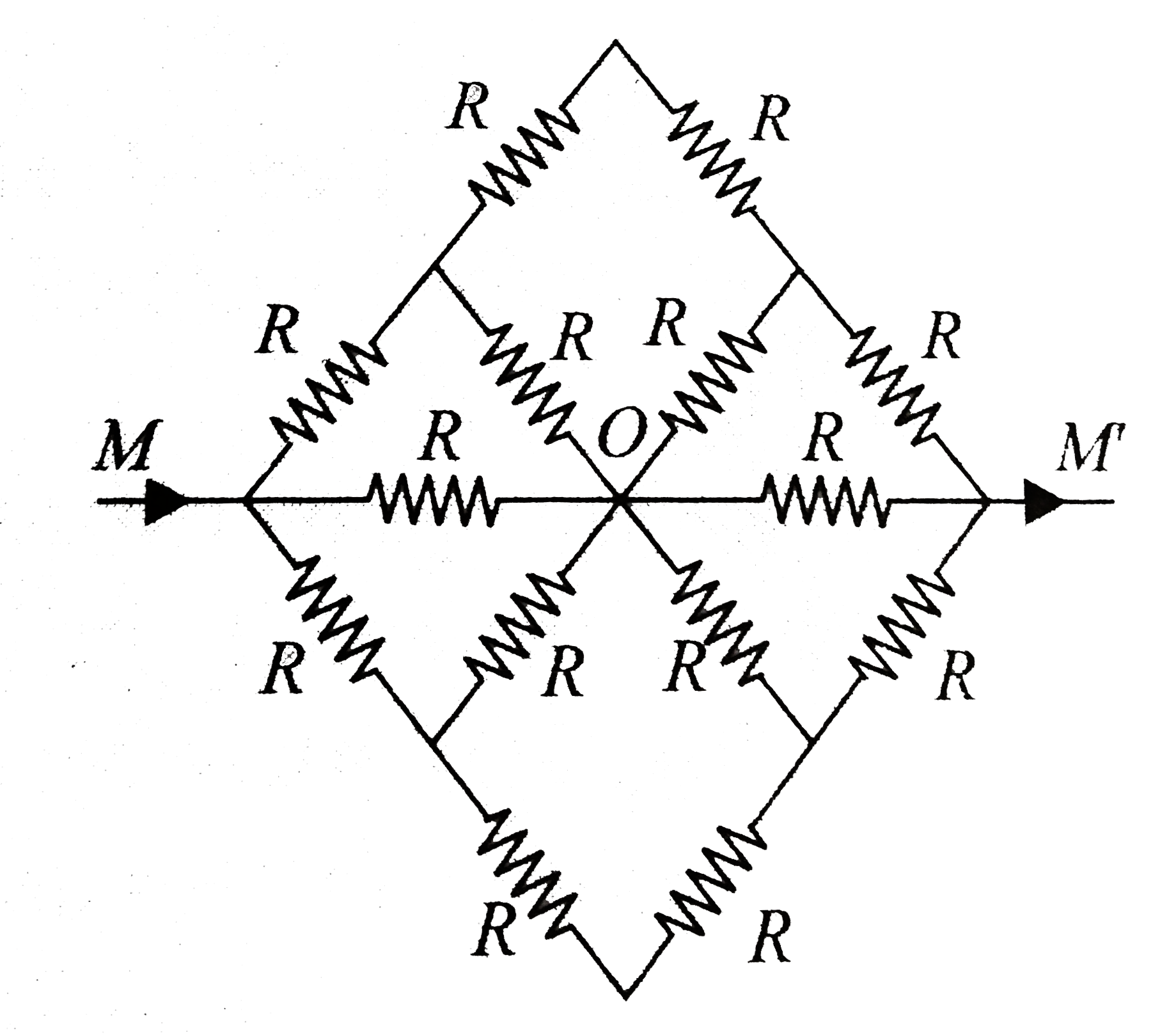
View Solutionln the network shown in Fig. 5.49. find the equivalent resistance across the points M and M'.
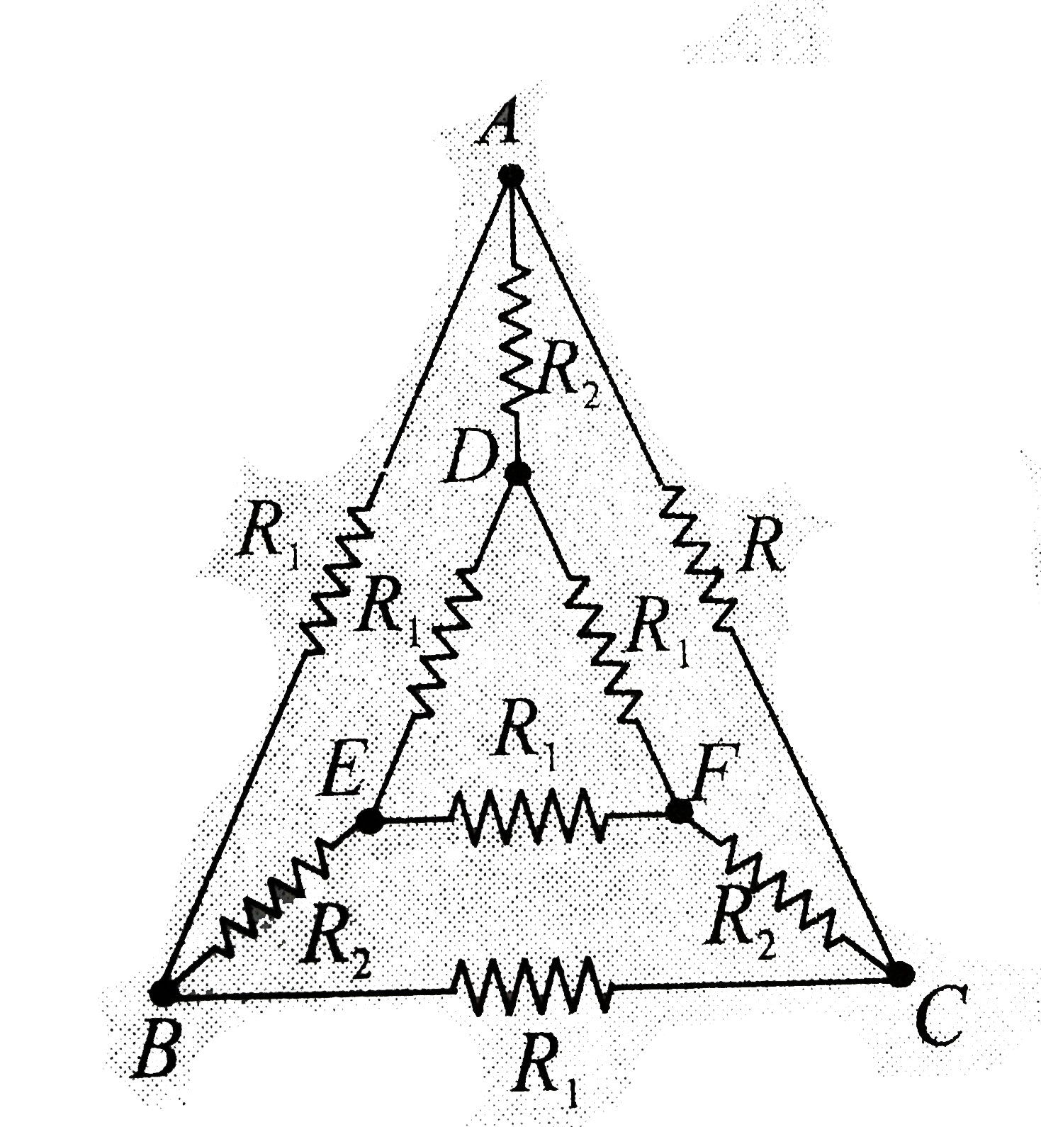
View SolutionIn Fig.5.52, the resistances are connected as shown. Given `R_1 = 10 OmegaR_2 = 20 Omega.` Determine the equivalent resistance between points (i) A and D and (ii) B and C
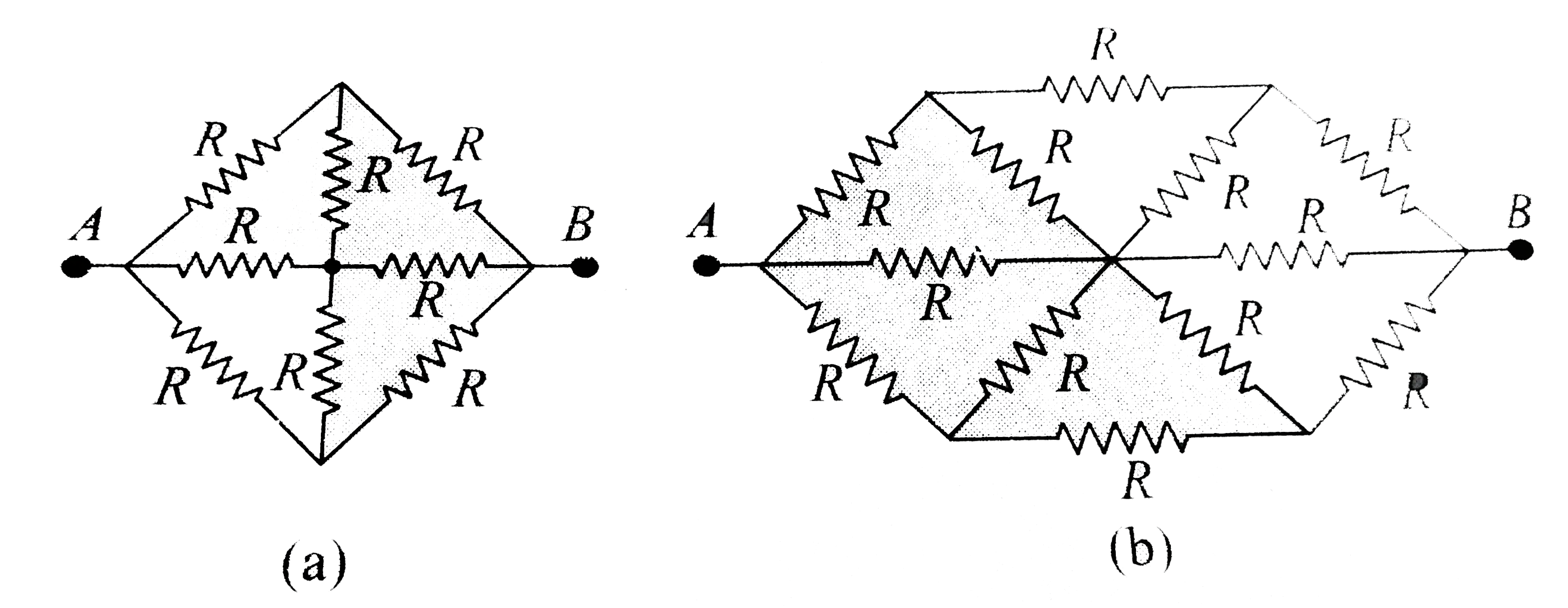
View SolutionIn the given circuits calculate the resstance between points A and B.
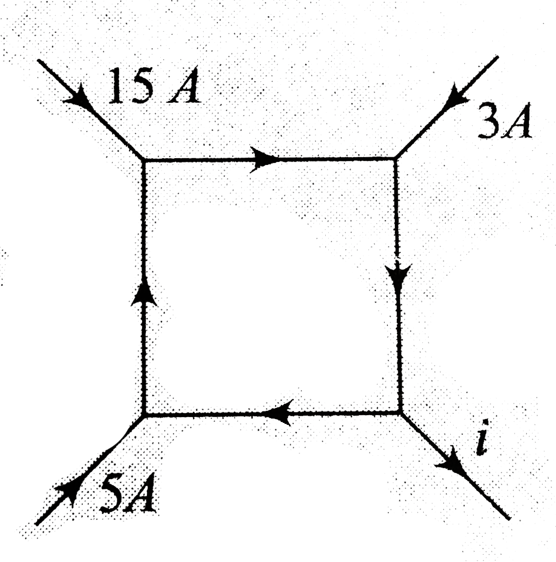
View SolutionShows a network of currents. The magnitude of the current is shown here. Find the current. i.
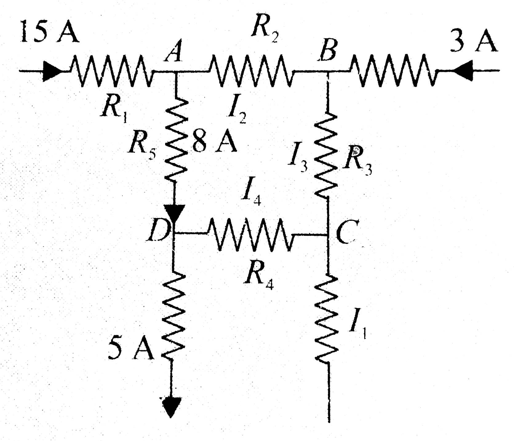
View SolutionCalculate the values of currents `I_1, I_2, I_3, and I_4` in the section of networks shown in Fig 5.64
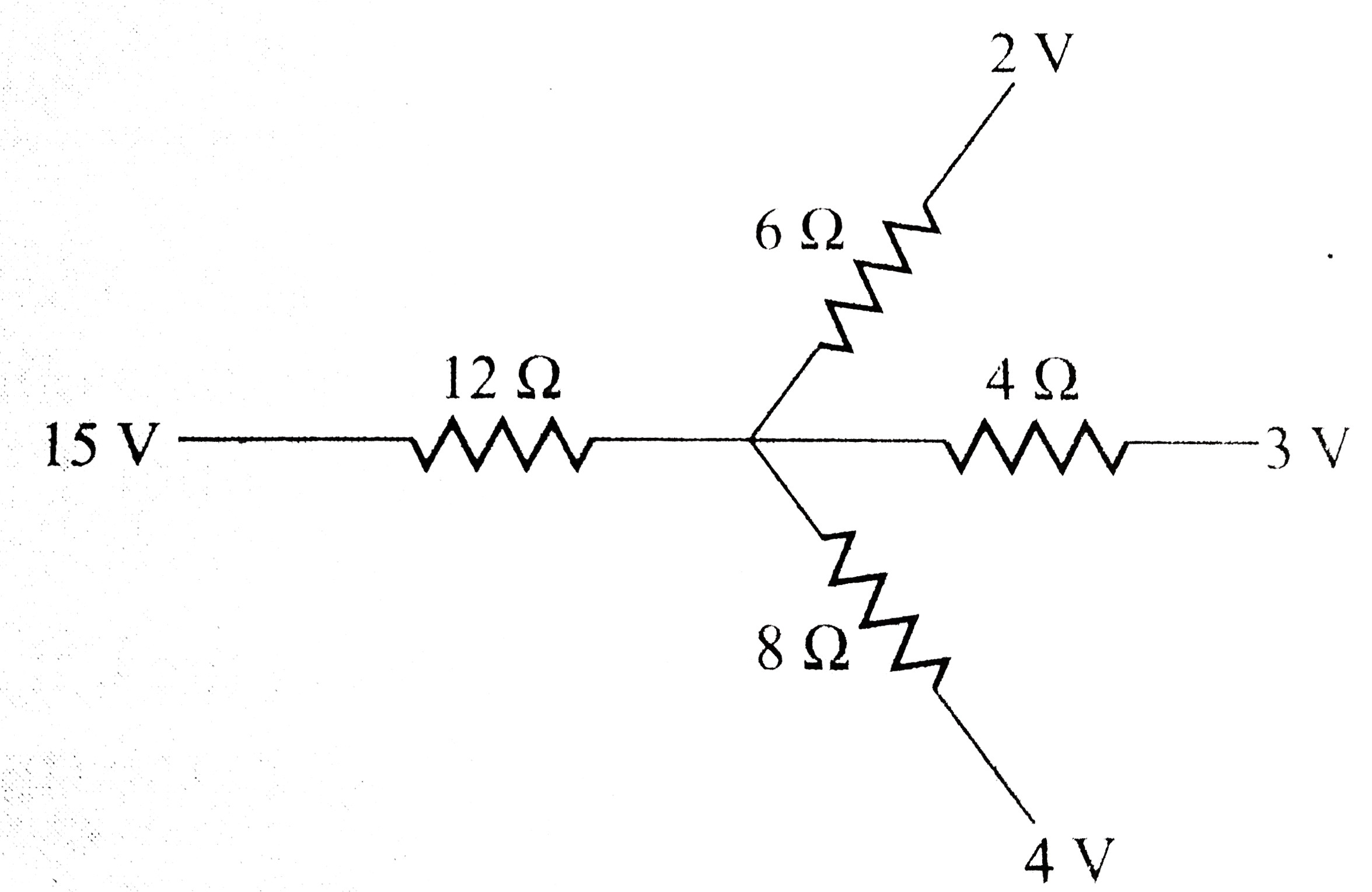
View Solutionshows three resistances are
connected with switch S initially the switch is open. When
the switch S is closed find the current passed through it.
View SolutionFind the current through `12 Omega` resistor in
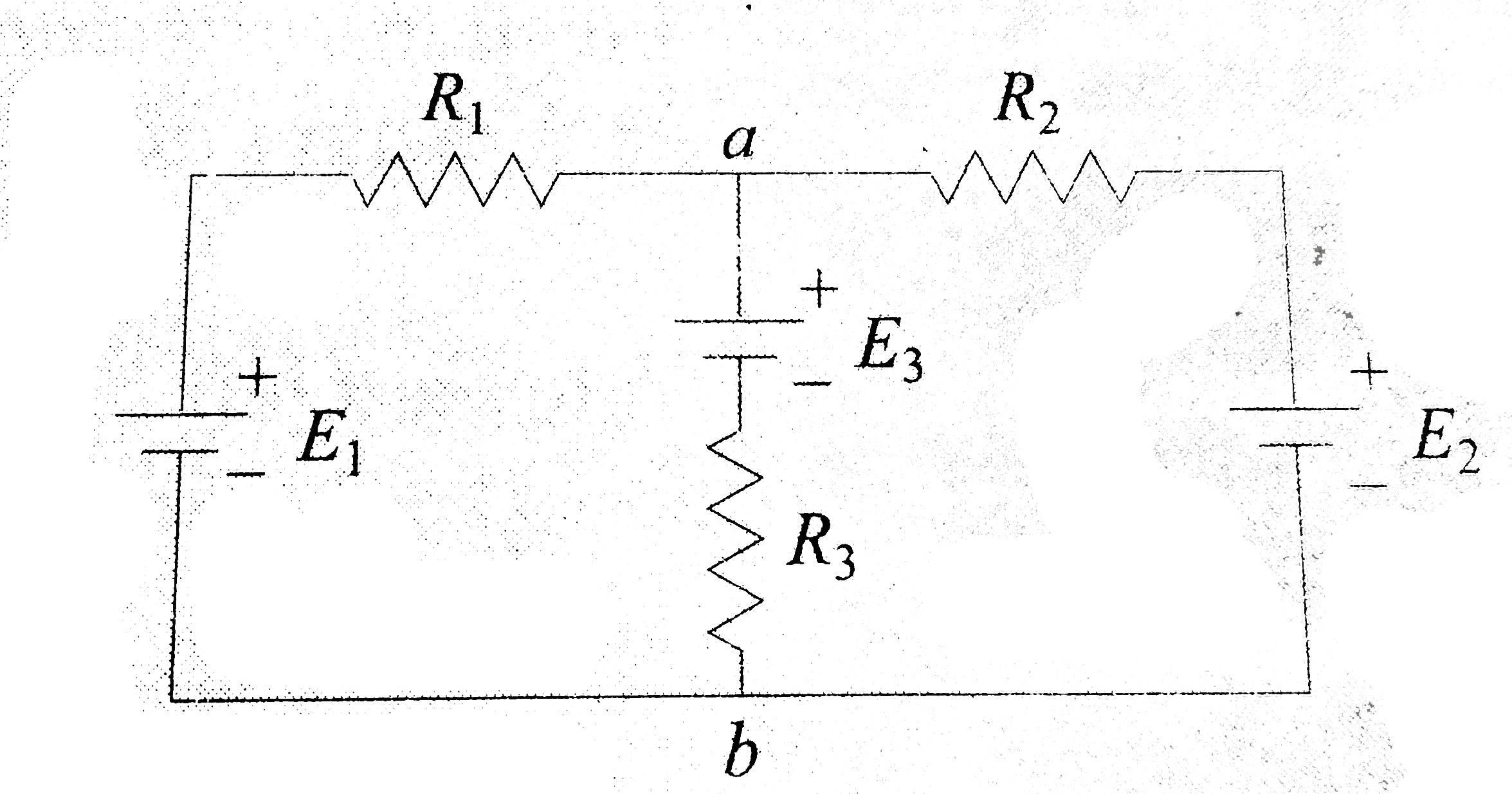
View SolutionCalculate the current through each resistance in the given circuit. Also calculate the potential difference between the points a and b.
`E_1 = 6V, E_2 = 8V, E_3 =10V`,
`R_1 =5 Omega`,` R_2 =10 Omega, R_3 =4Omega`
Assume that all the cless have no internal resistance.
View SolutionIn the circuit shown, find the current through the branch BD.
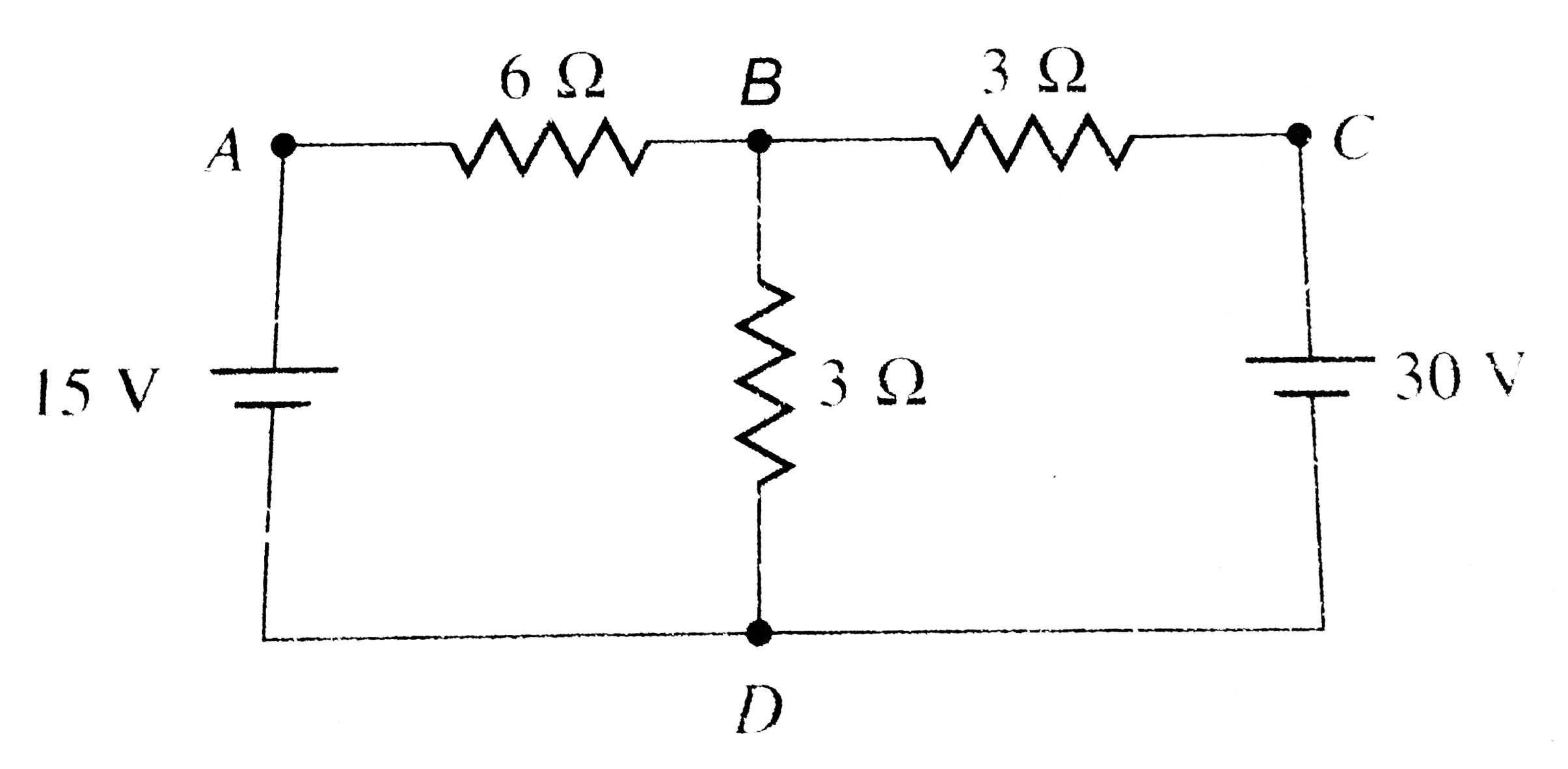
View SolutionIn the circuit shown in Fig. 5.79, determine the voltage drop between A and D.
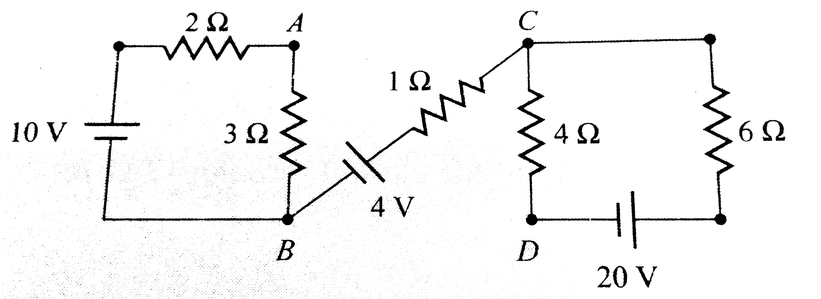
View SolutionFind the current in each part of the circuit.
View SolutionIn the circuit shown in E, F, G, and H are cells of emf 2,1,3 and 1 V, respectively. The resistances `2Omega, 1Omega, 3Omega and 1Omega` are their respectivle internal resistances.
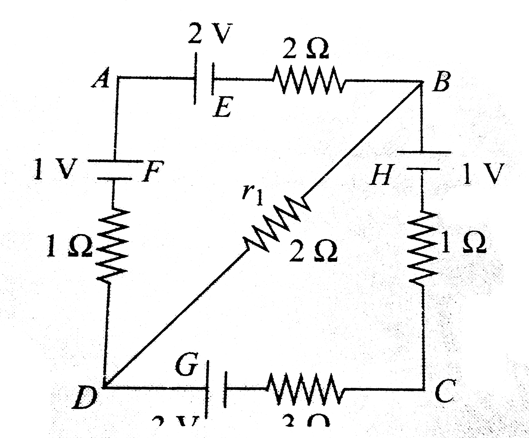
i. Find the potential difference between B and D.
(ii) Calculate the potential differences across the terminals of each of the cells G and H.
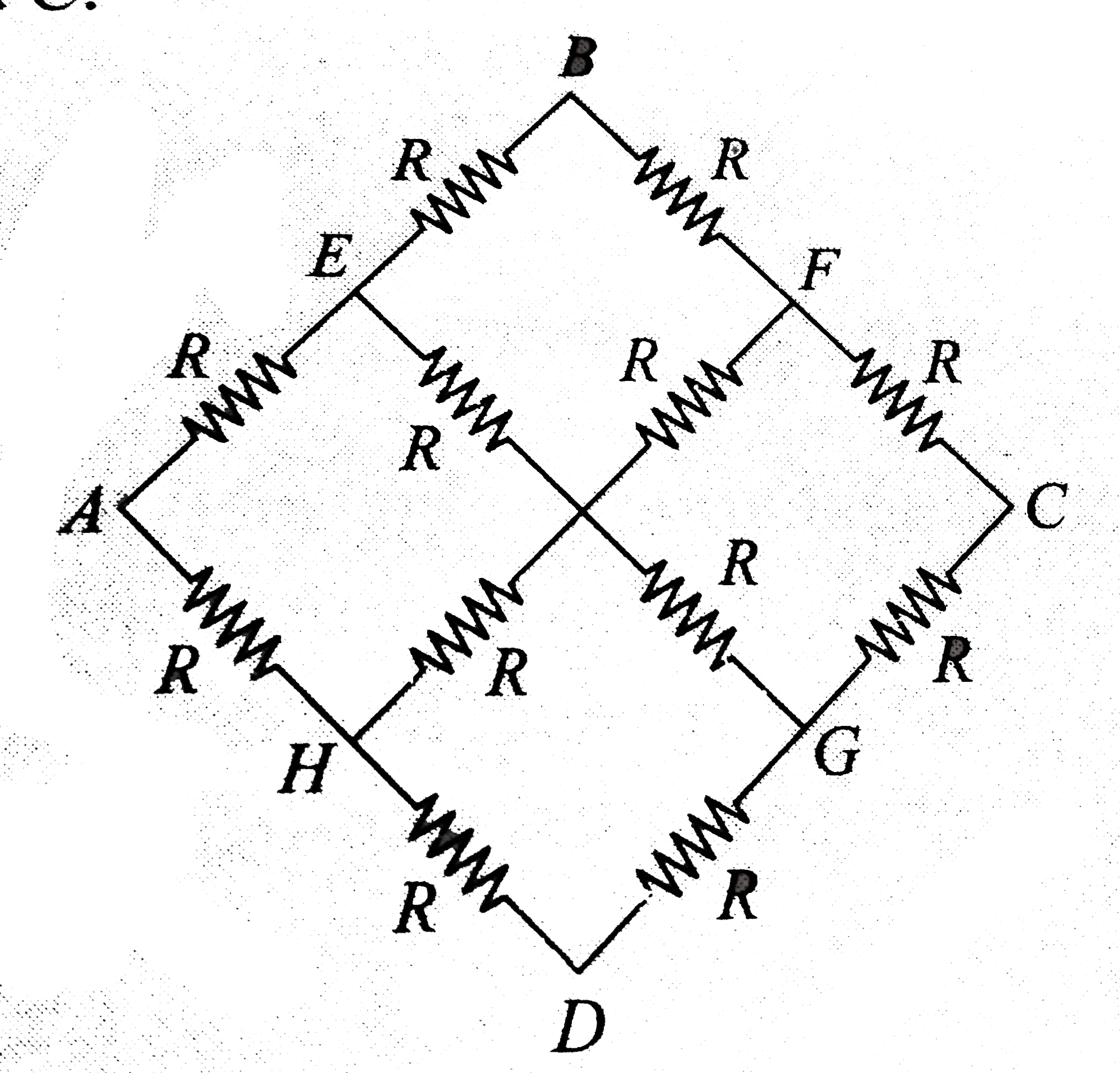
View SolutionIn the following network of 12 identical resistances, calculate the equivalent resistance between points A and C
View SolutionWhat will be the change in the resistance of a circuit between A and B, consisting of five identical resistances, if two similar resistances are added as shown by the dashed line in

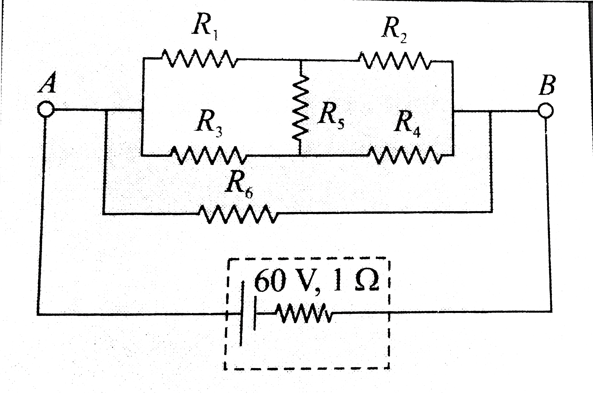
View SolutionResistances `R_1, R_2, R_3, R_4, R_5, and R_6` are connected with a 6V battery with internal resistacne `1Omega` as shown in fig 5.90. Find (a) equivalent resistance and (b) current in each resistacne.
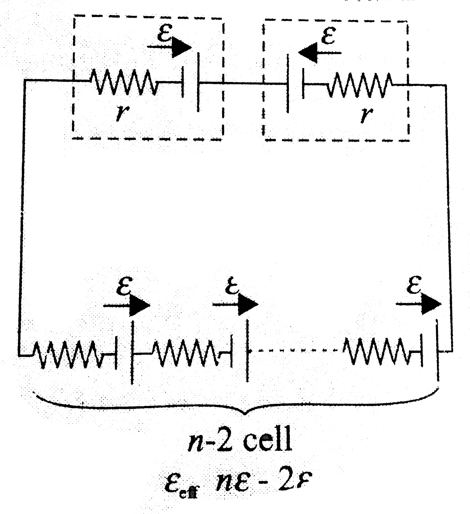
View Solutionn identical cells each of emf 6 V , connected in series with an external resistor of `5Omega`, carry a current of `10A`. If two cells are connected wrongly in series with the same external resistor, the current flowing through the cells will be 8A. Find the value of n and r the internal resistance of each cell.
View Solutionn identical cells, each of emf E and internal resistance r, are joined in series to form a closed circuit. Find the potential difference across any one cell.
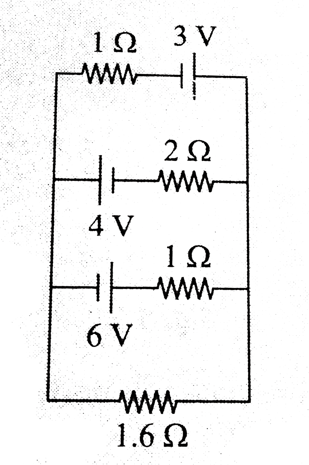
View SolutionThree cells of emf 3V, 4V, and 6V are connected in parallel, If their internal resistances are `1 Omega`, `2 Omega` and `1 Omega` find the `epsilon_(eff), r_(eff)`, and the current in the external load R = 1.6 `Omega` .
View SolutionIn the circuit shown,
i. `V_A - V_B = ……..
(ii) I_1 = …….
(iii) I_2 ……..
iv. I = ……..
View SolutionIn a mixed grouping of identical cells, five rows are connected in parallel and each row contains 10 cells. This combination sends a current I through an external resistance of `20Omega.` if the emf and internal resistance of each cell is 1.5 V and `1 Omega,` respectively then find the value of I.
View Solution100 cells each of emf 5V and internal resistance `1 Omega` are to be arranged to produce maximum current in a `25 Omega` resistance. Each row contains equal number of cells. Find the number of rows.
View SolutionThe resistance and batteries are connected as shown in. The potentials at points B,C,D, and E are assigned as shown. Find the potential at point A.


View SolutionGiven below find the current in the wire BD.
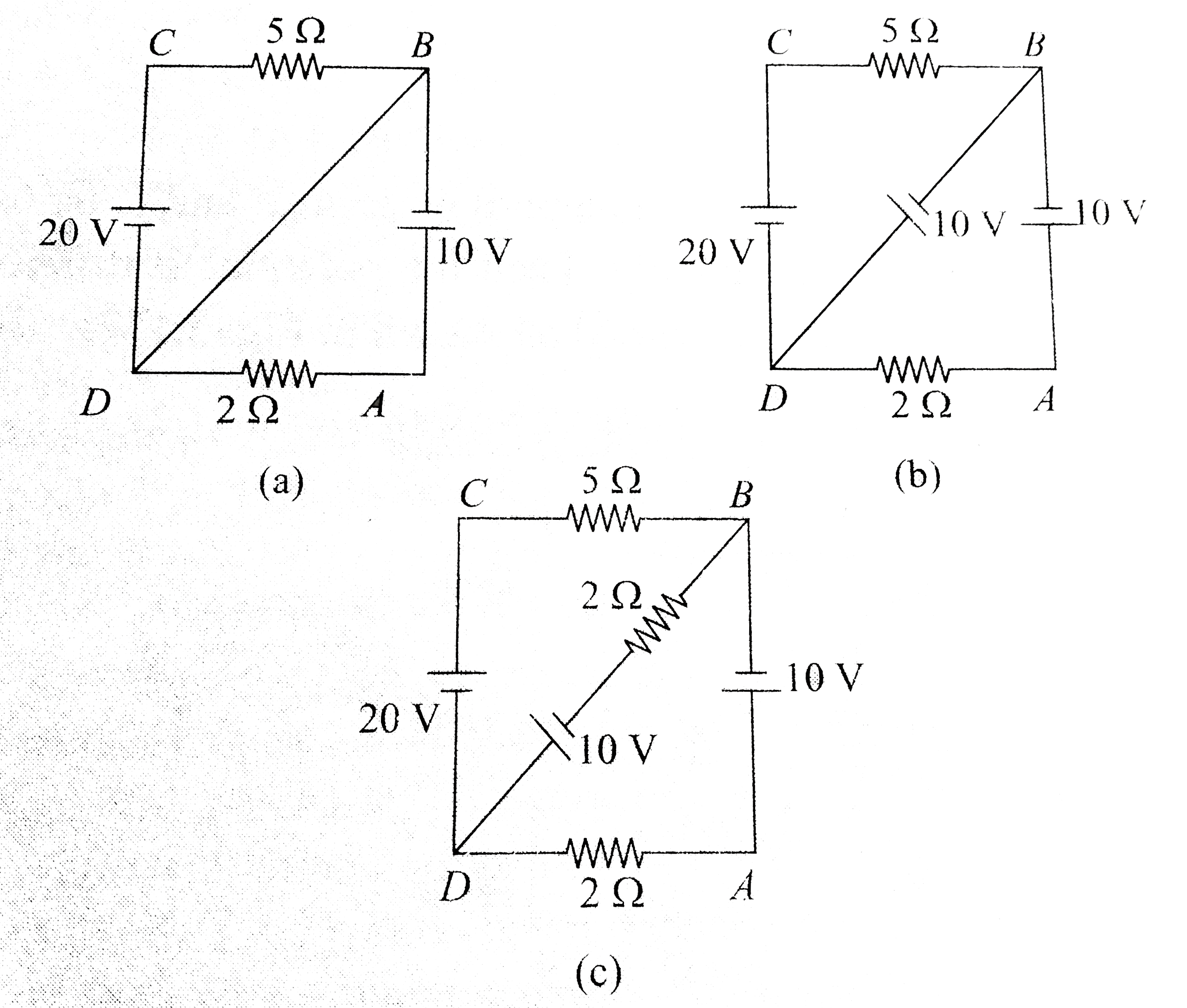
View SolutionFind the current in each wire.
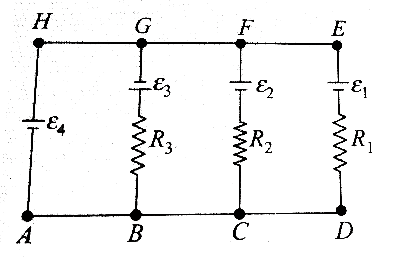
`epsilon_1 = 50V, epsilon_2 = 40V`
`epsilon_3 =30 V, epsilon_4 = 10V`
`R_1 = 2Omega, R_2 = 2Omega`
`R_3 = 1Omega`
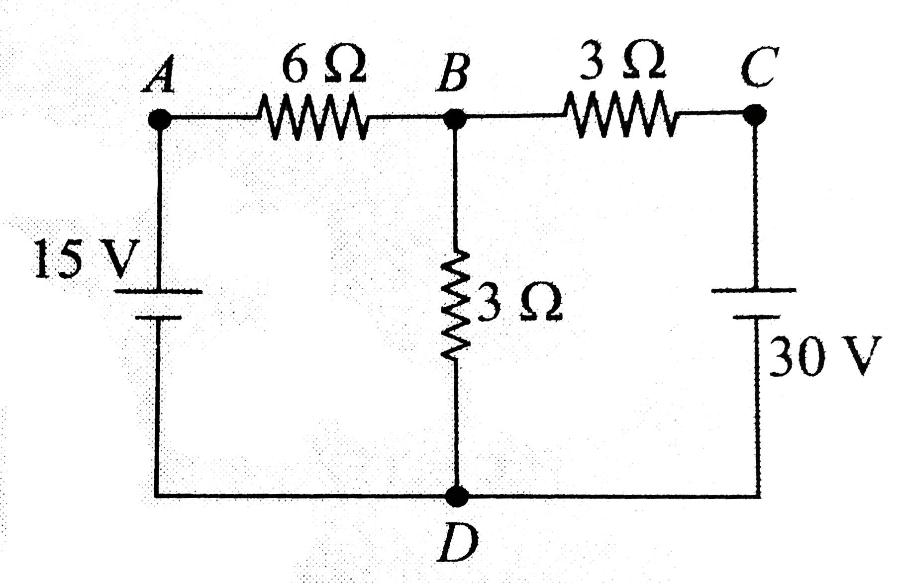
View SolutionIn the circuit shown in fig. find the current through the branch BD.
View SolutionTweleve indentical resistor are arranged on all edfges of a cube. Then find the equivalent resistance between the corners 1 and 6 as shwon in fig 5.126(us nodal method)
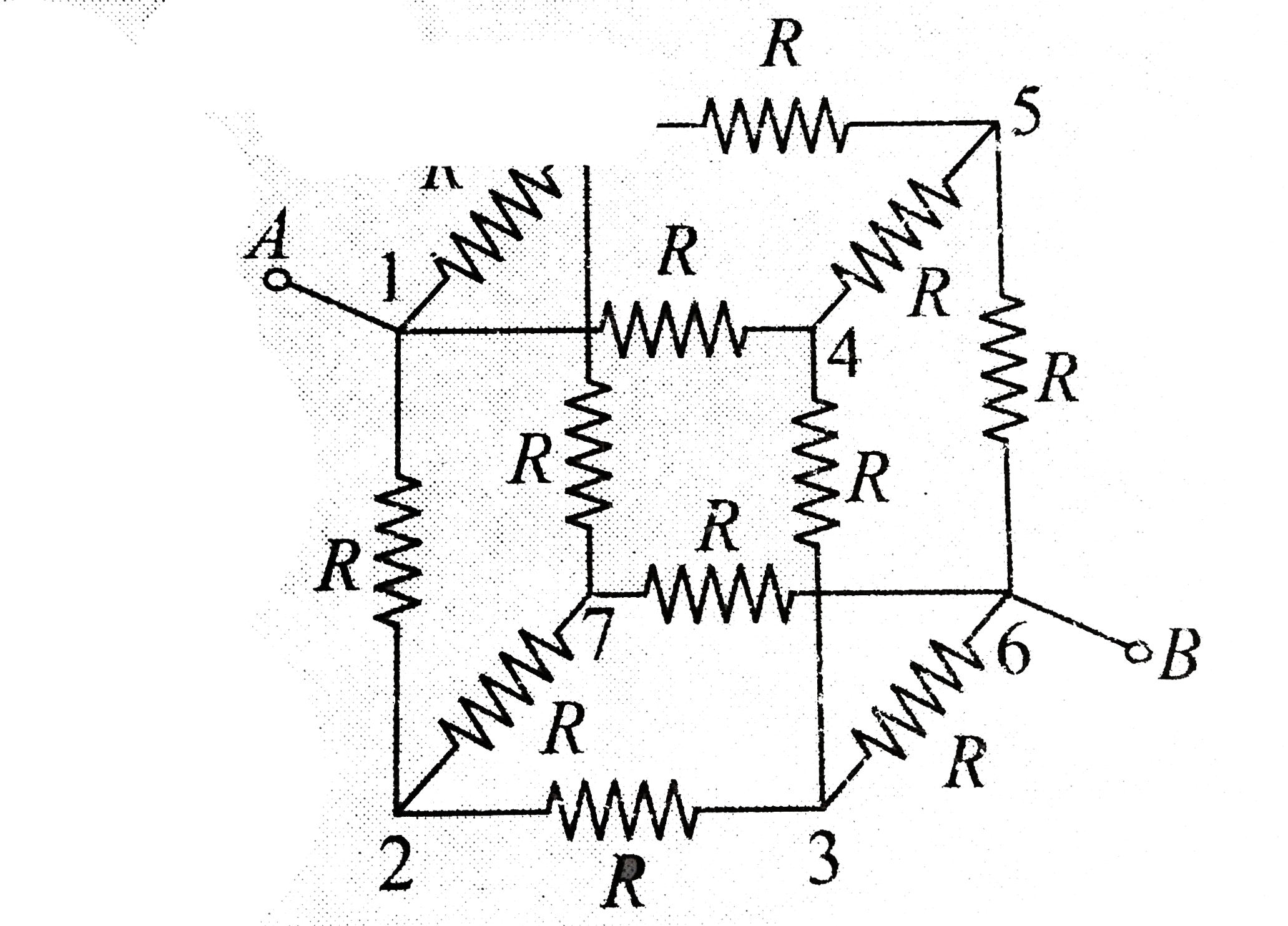
View SolutionIn previous illustration, find the equivalent resistance of the network between 1 and 2.
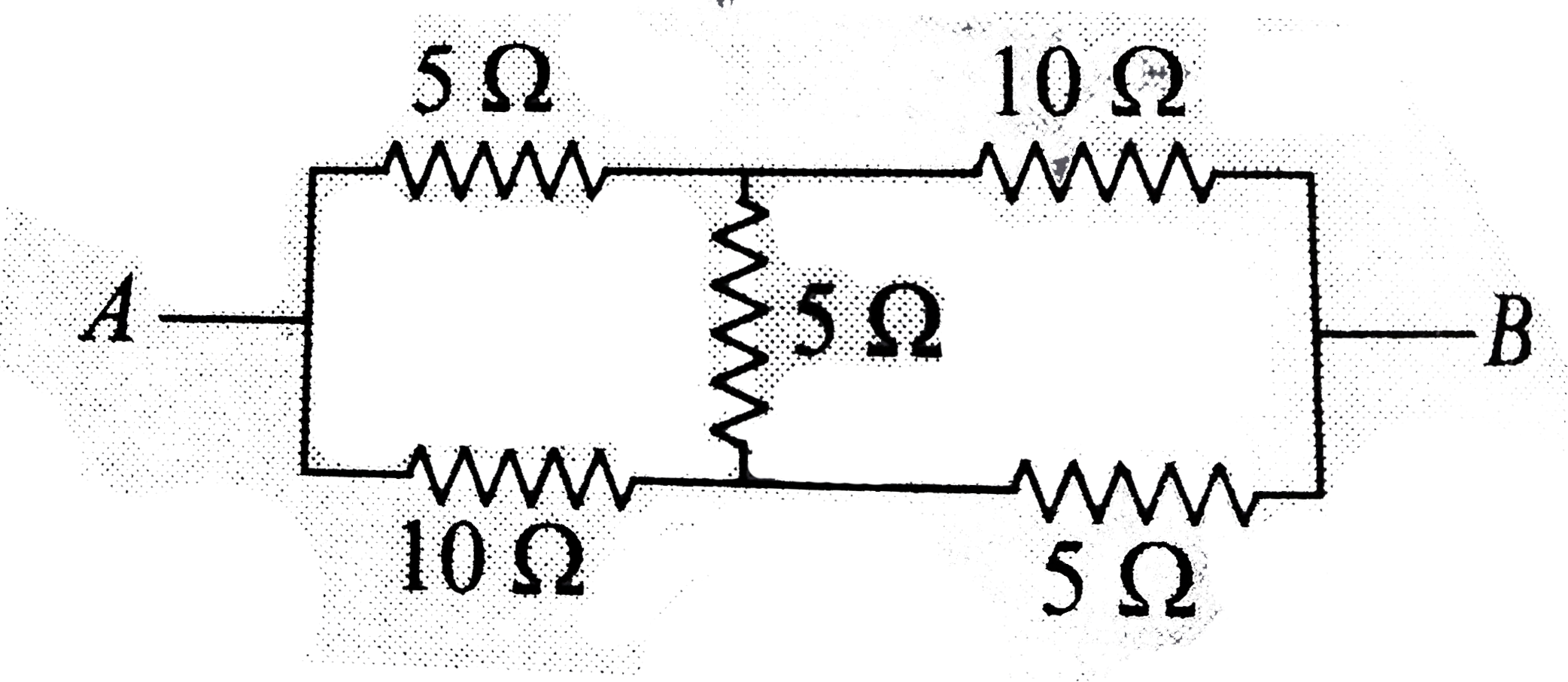
View Solutionfind the equivalent resistance between A and B.
View SolutionA resistor with resistance `10MOmega` is connected in series with a capacitot of capcitance `1.0muF` and a battery with emf 12.0V, Before the switch is closed at time t= 0 the capacitor is uncharged.
a. What is the time constant?
b. What fraction of the final charge is on the plates at tiem t = 46s?
c. kWhat fraction of the inital current remians at t =46?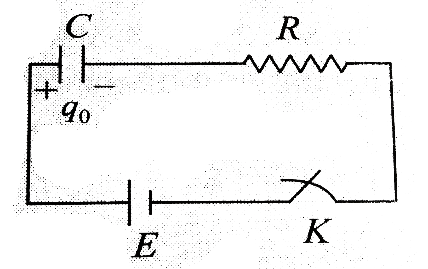
View SolutionAn uncharged capacitor is connected to a 15 V battery through a resistance of `10Omega.` It is found that in a time fo `2mus,` potential difference across the capacitor. Take in (1.5) = 0.4.
View SolutionConsider the circuit shown in fig 5.168. Find out the steady - state current in the `4Omega` resistor. Assume the internal resistance of 8 V battery to be negligible.
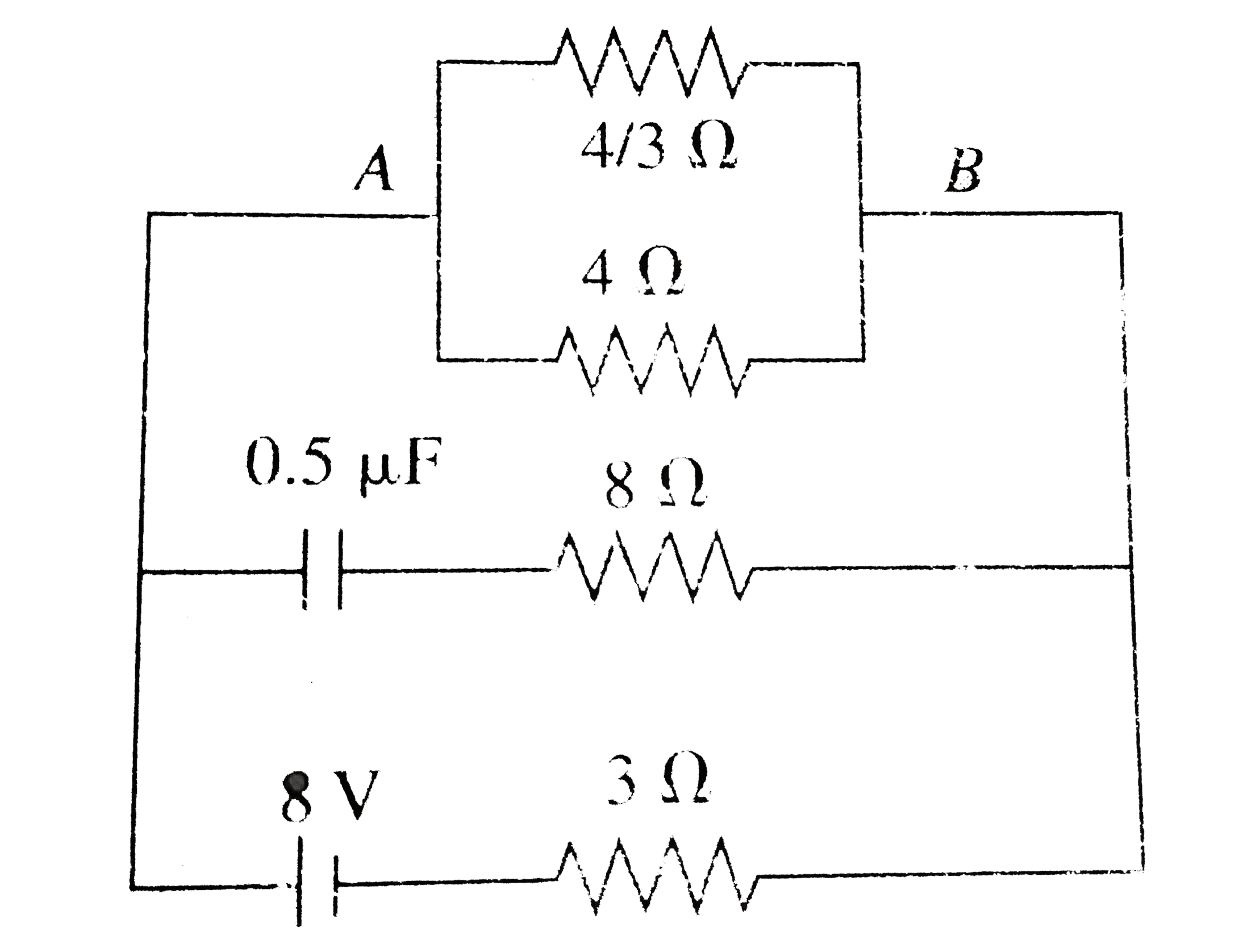
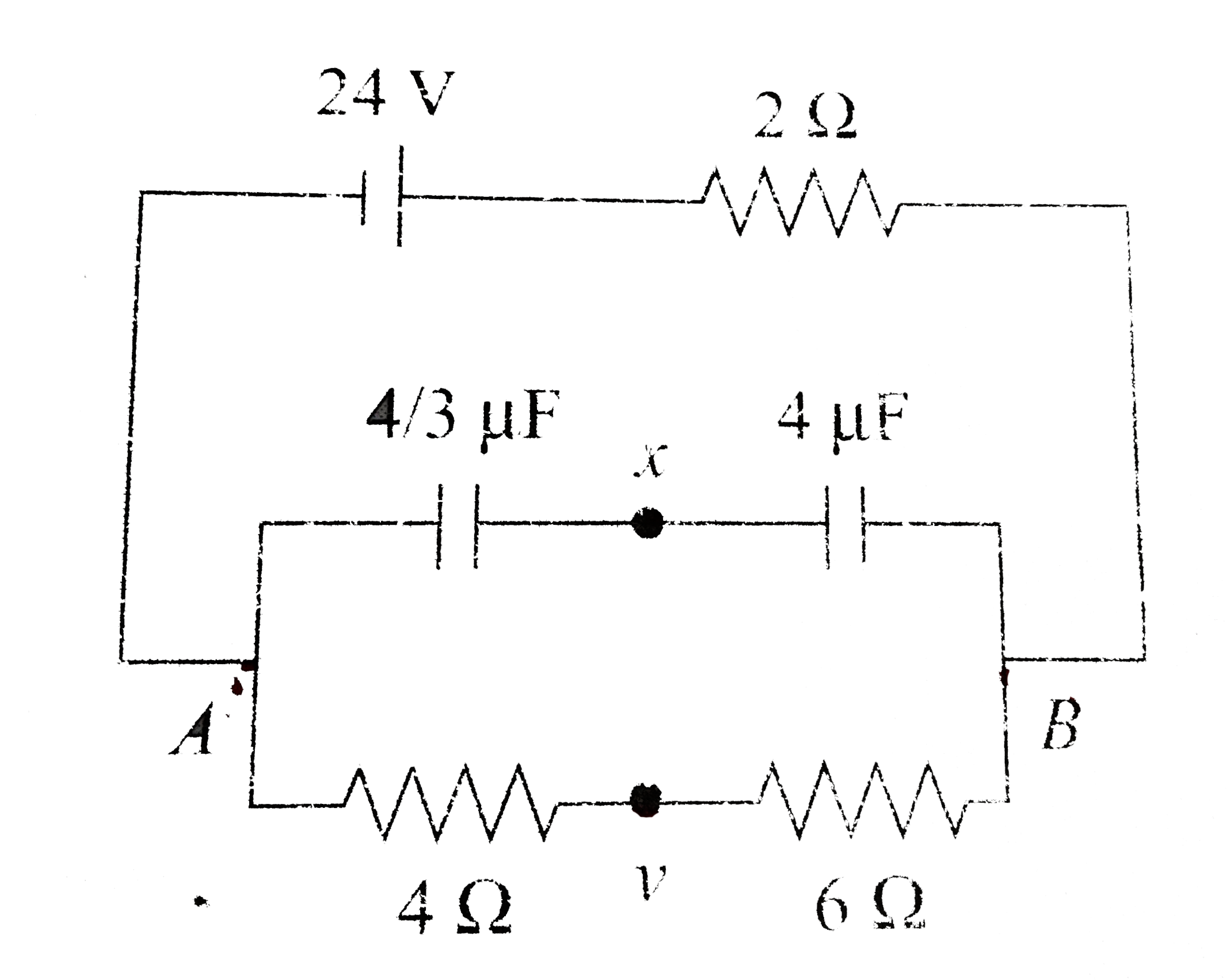
View SolutionFind out the potential difference between the points x and y in fing 5.169.
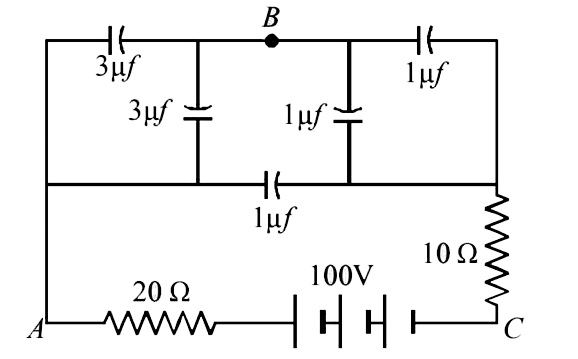
View SolutionIn the diagram shown find the potential difference between the points A and B and between the points B and C in the steady state.
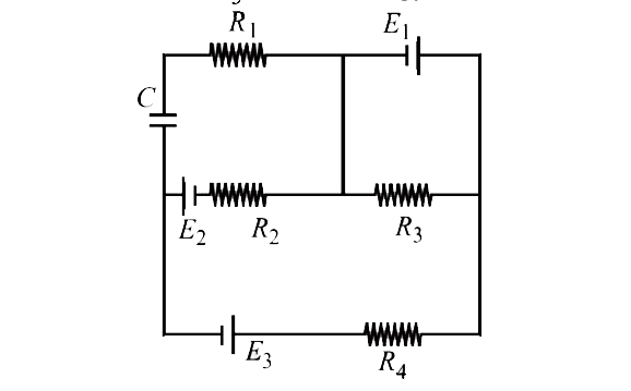
View SolutionIn the given circuit
`E_1 = 3E_2 = 2E_3 =` 6 volts `R_1 = 2R_4 = 6Omega`
`R_3 = 2R_2 = 4Omega` `C = 5 muf.`
Find the current in R and the energy stored in the capacitor.
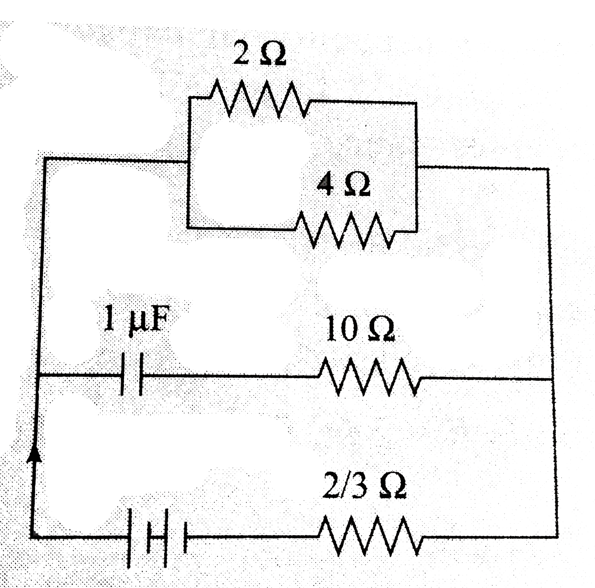
View SolutionConsider the circuit shown in fig 5.174 where a battery of emf 4V and a capacitor of capacitance 1 `muF` is connected to a combination of resistacnes. Find out the stedy-state current in the battery.
View SolutionA capacitor of capacitance `10muF` is connected to a resistance `2Omega` and a battery of emf 5V of negligible interanl resistance. After `20mus` of comleting the circuit find.
a. power delivered by the battery
b. power dissipated as heat
c. rate of energy stored in the capacitor
View SolutionA resistor and a capacitor are connected as shown in fig. 5.178. The capacitor is originally given a charge of `5.0muC` and then discharged by closing the swtich at t =0.
a. At what tiem will be charge be equal to `0.50muC`?
b. What in the current at this time?
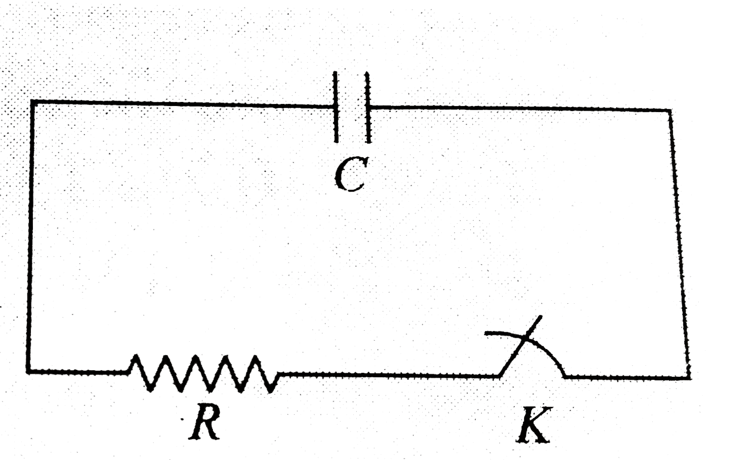
View SolutionA capacitor charged to `50 V` is discharged by connecting the two plates at `t=0`.If the potential difference across the plates drops to 1.0 V at t=10 ms,what will be the potential difference at t=20 ms?
View SolutionA `5.0(mu)F` capacitor having a charge of `(20 (mu)C)`is discharged through a wire aof resistance `(5.0 Omega)`. Find the heat dissipated in the wire between 25 to `50 (mu)s after the connections are made.
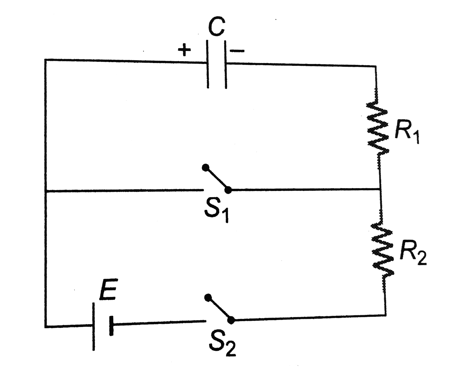
View SolutionThe capacitor shown in figure has been charged to a potential difference of `V` volt, so that it carries a charge `CV` with both the switches `S_1 and S_2` remaining open. Switch `S_1` is closed at `t = 0`. At `t= R_1C` switch `S_1` is opened and `S_2` is closed. Find the charge on the capacitor at `t= 2R-1C + R_2C`.
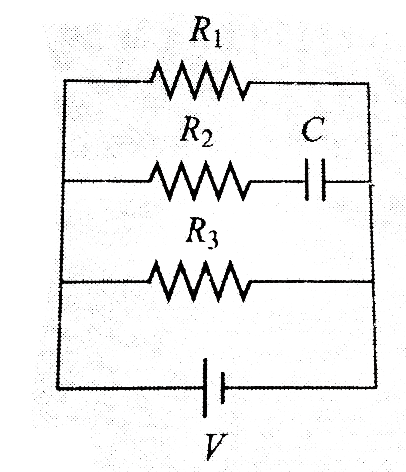
View SolutionCalculate the current in bracnhes containing `R_1, R_2 and R_3` in the circuit shown in
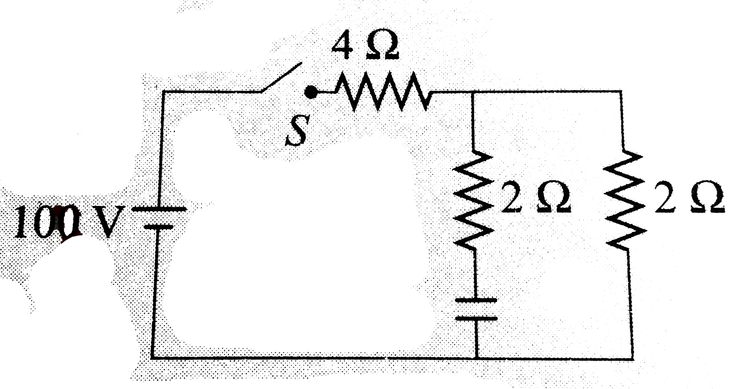
View SolutionCalculate the current flowing through the capacitor branch in the circuit shown in Fig. 5.187, initially and finally,
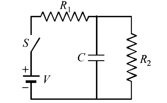
View SolutionIn the given circuit, the switch S is closed at time t = 0 . The charge Q on the capacitor at any instant t is given by `Q(t) = Q(1-e^(-alphat))`. Find the value of `Q_0` and `alpha` in terms of given parameters as shown in the circuit.
 .
.
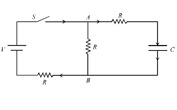
View SolutionIn the circuit shown in Figure, the battery is an ideal one, with emf V. The capacitor is initially uncharged. The switch S is closed at time t = 0 .
(a) Find the charge Q on the capacitor at time t.
(b) Find the current in AB at time t. What is its liniting value as `t rarr oo`:
 .
.
View Solution
Illustration questions and complete solutions for chapter ELECTRIC CURRENT AND CIRCUIT of CENGAGE PHYSICS (HINGLISH) of Class 12