Complete Solutions to Single Correct of chapter ELECTRIC CURRENT AND CIRCUIT of Class 12 book with complete answers and questions
| Class 12 | PHYSICS |
| Chapter | ELECTRIC CURRENT AND CIRCUIT |
| CENGAGE PHYSICS | Single Correct |
| Number Of Questions | 72 |
| Academic Year | 2023-24 |
Equivalent resistance between A and B in Fig. is
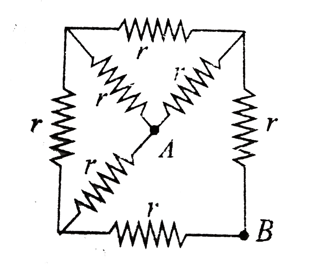
View SolutionEach of the resistor shown in fig. has resistance R. Find the equivalent resistance between A and B
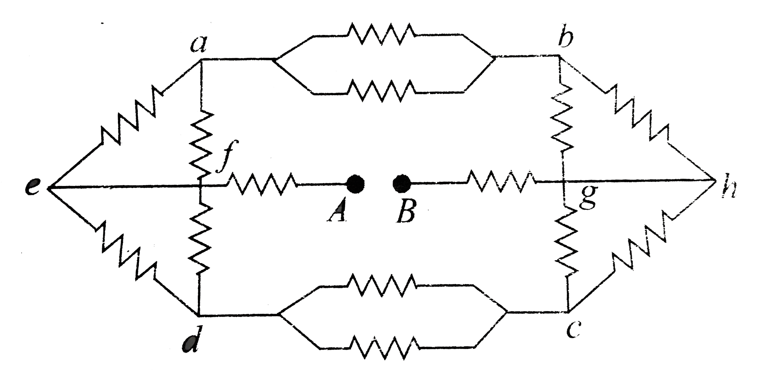
View Solutionfind the equivalent resistance between A and E(resistance of each resistor is R.
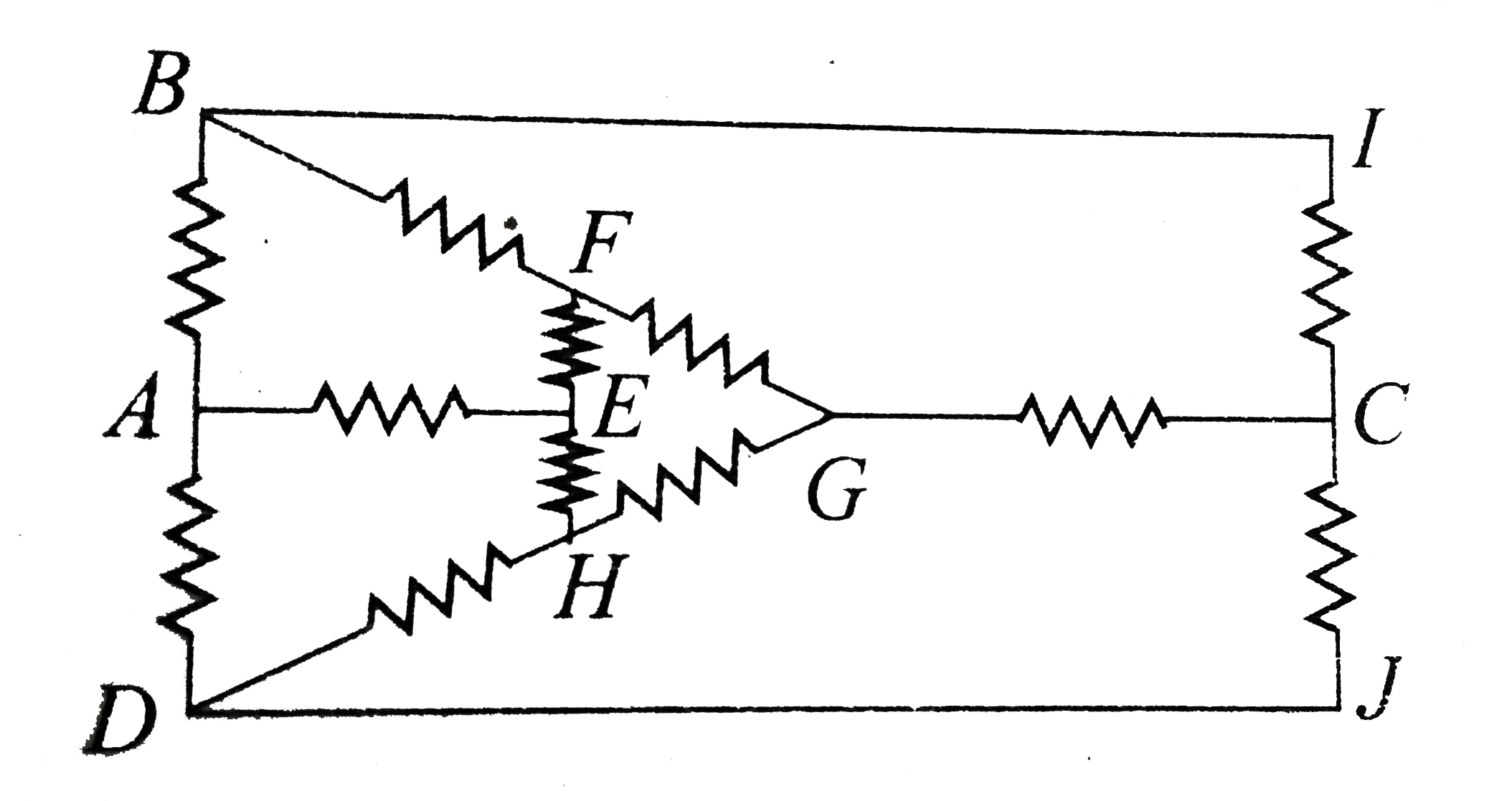
View SolutionThe circuit shown has resistor of equal resistance R. Find the equivalent resistance between A and B, when the key is closed.
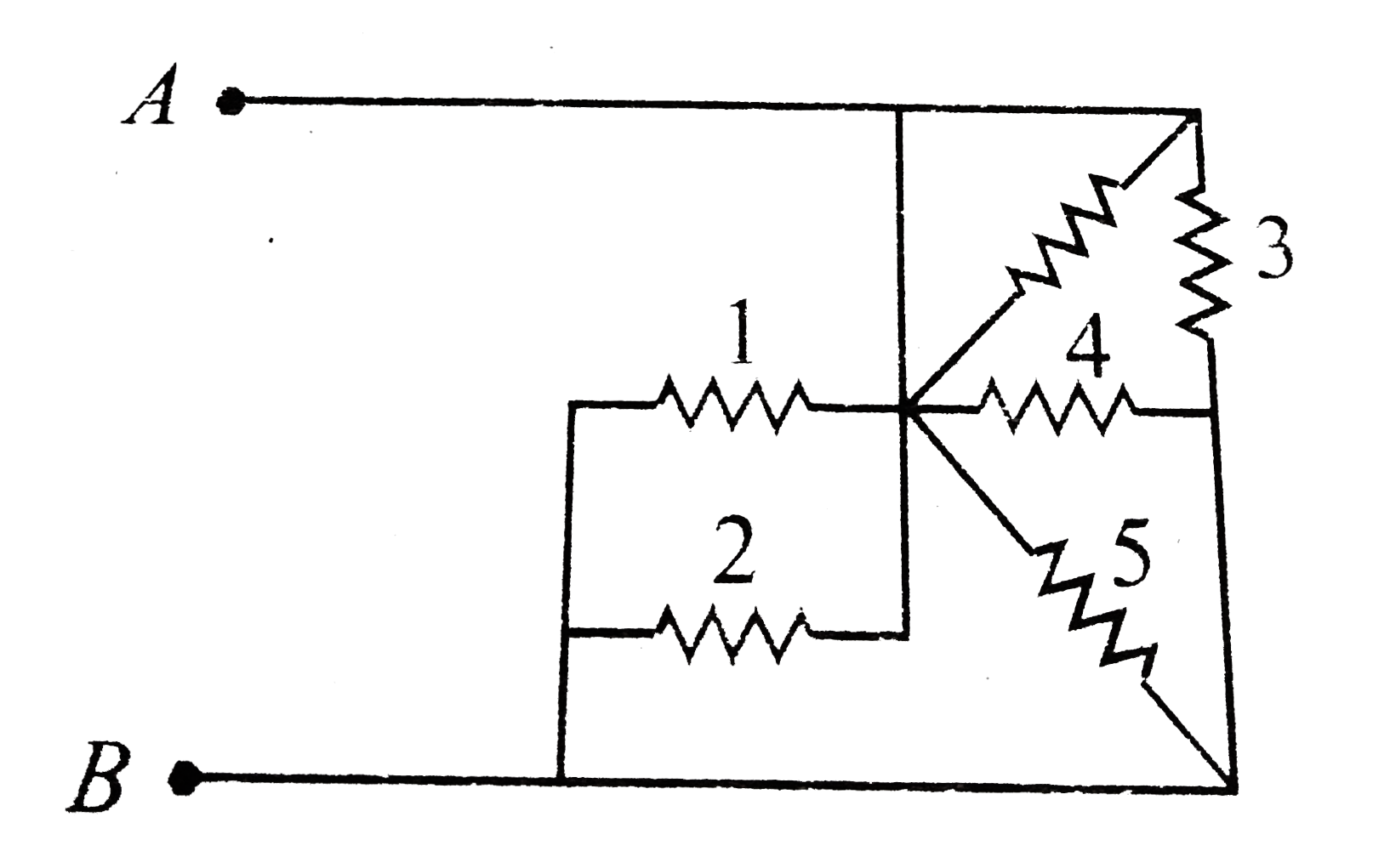
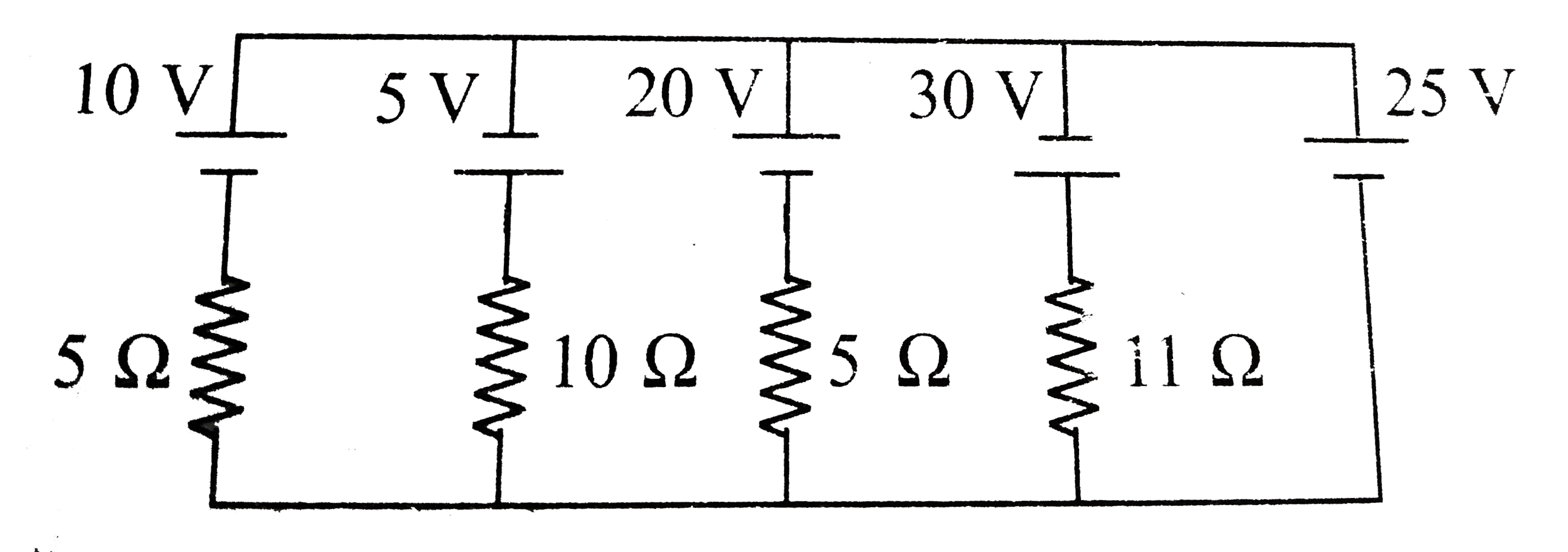
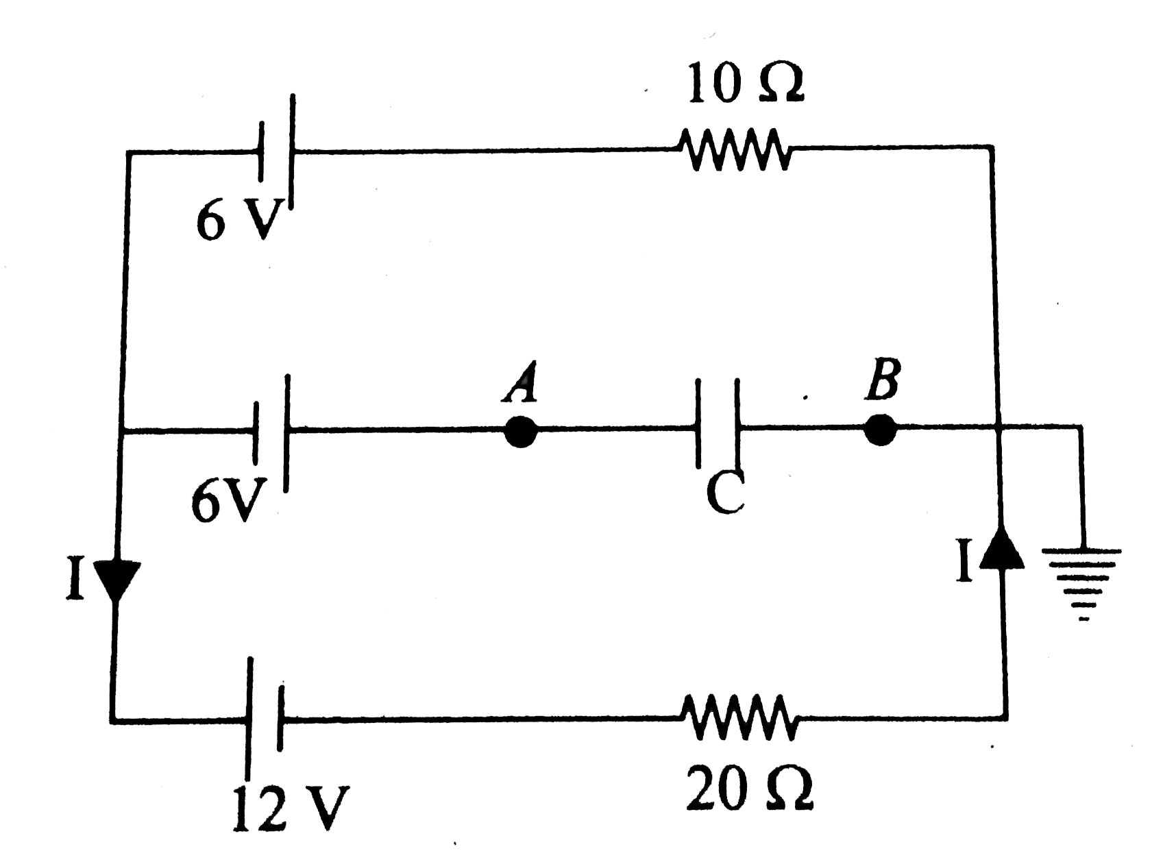
View SolutionIn the circuit shown, current through 25V cell is
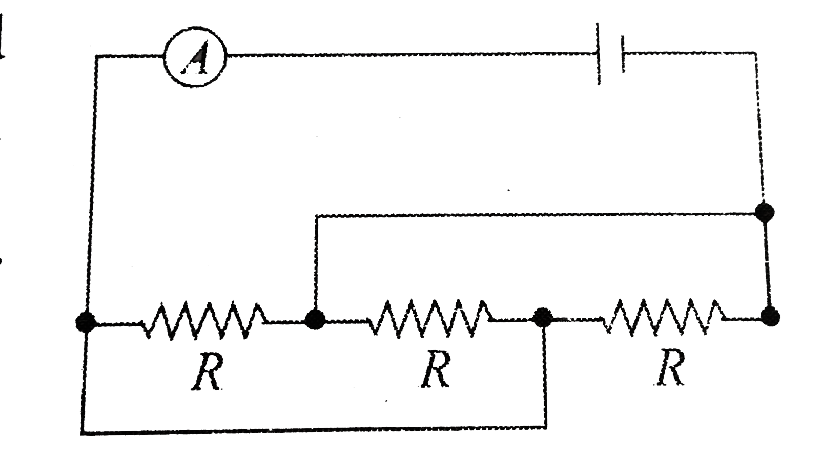
View SolutionFigure represents a load consisting of three identical resistances connected to an electric enrgy source of emf 12 V and internal resistance `0.6Omega.` The ammeter reads 2A. The magnitude of each resistance is
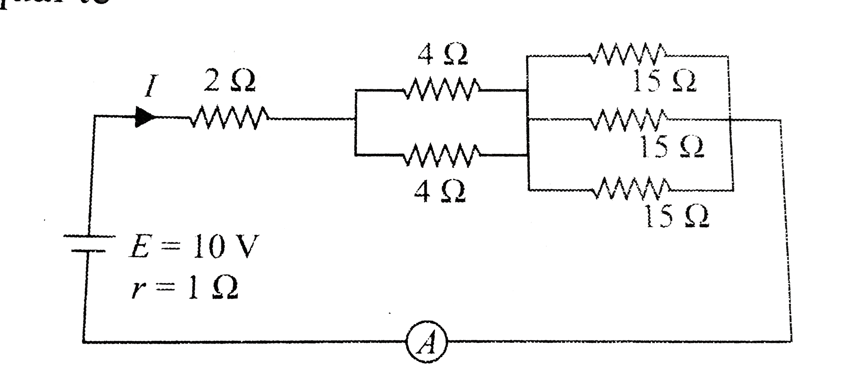
View SolutionIn the circuit shown in fig. the current I has a value equal to
View SolutionFigure 5.260 shows two square, X and Y cut from a sheet of metal of uniform thickness t. X and Y have sides of length L and 2L, respectively.

The resistances `R_x and R_y` of the squares are measured between the opposite faces shaded in fig. What is the value of `R_x//R_y?`
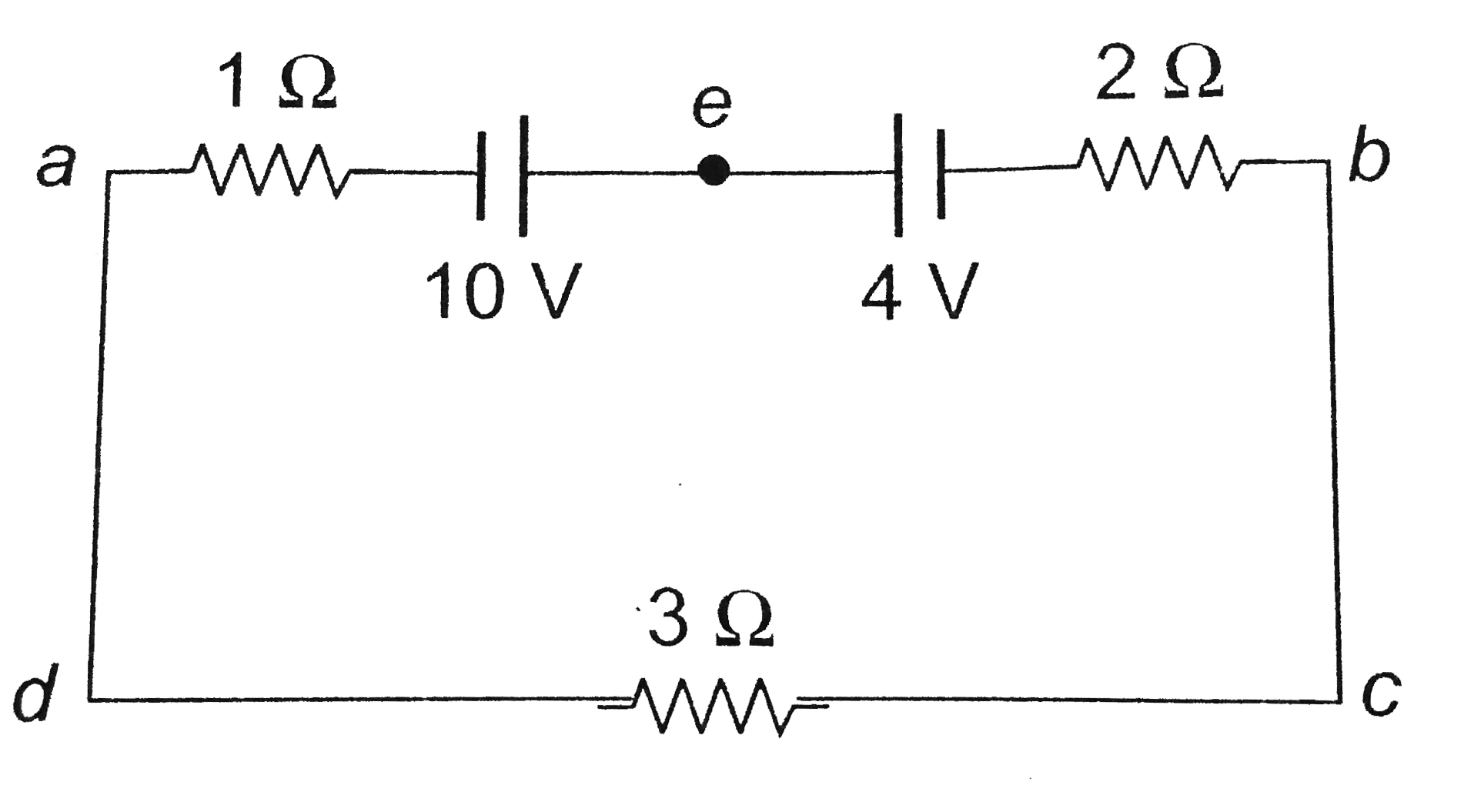
View SolutionThe magnitude and direction of the current in the circuit shown will be
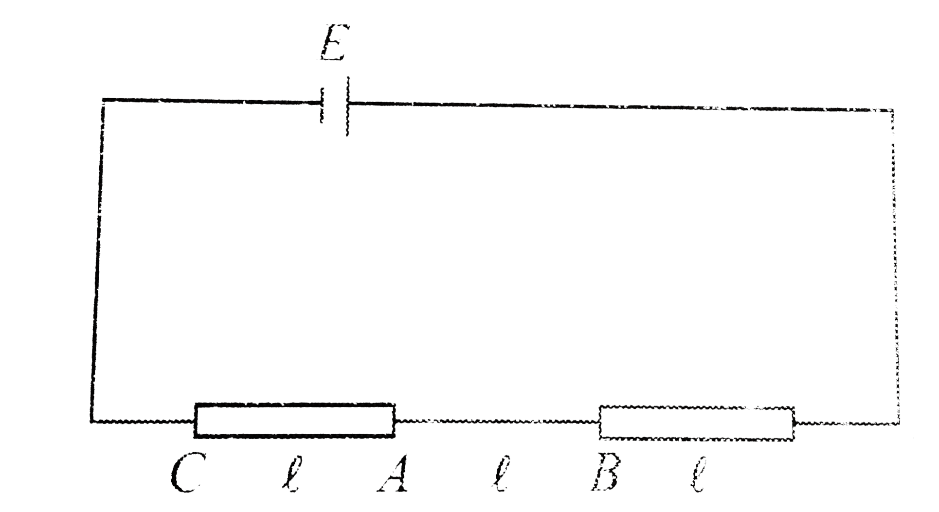
View SolutionA cell ofemf E volt with no internal resistance is connected to a wire whose cross section chages. The wire has three sections of equal length. The middle section has a redius a, whereas the radius of the outer two sections is 2a. The raito of the potential differece across section AB to the potential differecne across section CA is
View SolutionThe plot represents the flow of current through a wire at three different times. The ratio of charges flowing through the wire at different times is

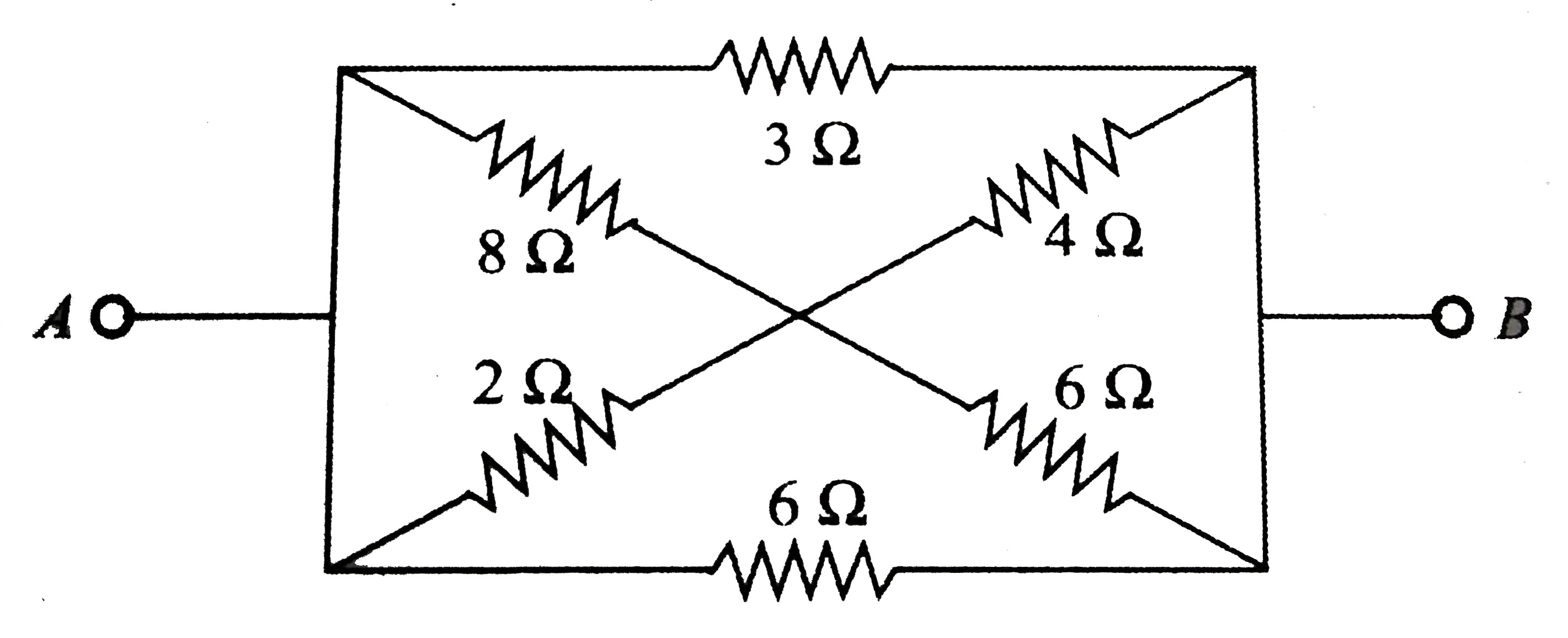
View SolutionThe equivalent resistance between A and B in the network in fig.,
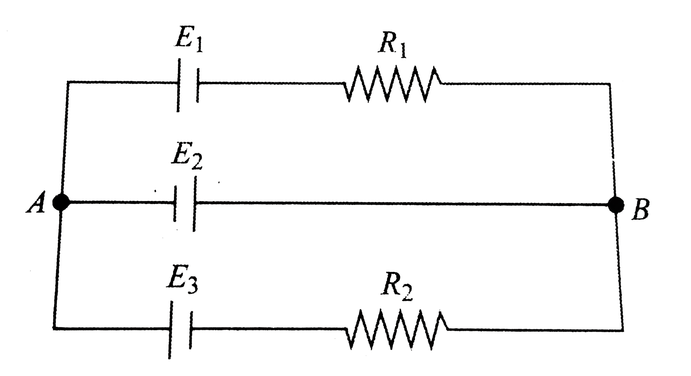
View SolutionIn the circuit shown in fig. 5.265, `E_1 = E_2 = E_3 = 2V` and `R_1 = R_2 = 4Omega.` The current flowing between points A and B through battery `E_2` is
View SolutionResistance of a resistor at temperature `t^@C is R_t =R_0 (1+alphat + betat^2)`, where `R_0` is the resistance at `0^@C`. The temperature coefficient of resistance at temperature `t^@C` is
View SolutionThe masses of the three wires of copper are in the ratio 1 : 3 : 5. And their lengths are in the ratio 5 : 3 : 1. the ratio of their electrical resistance is
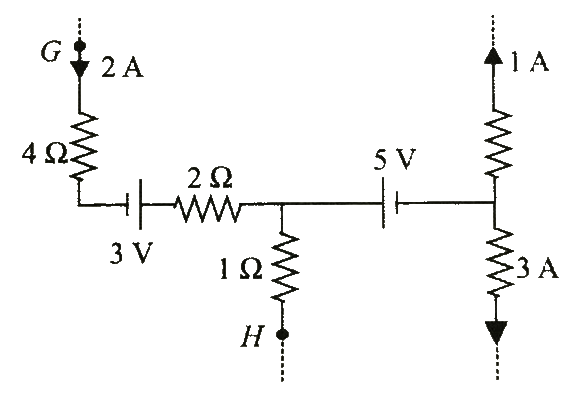
View SolutionIn the part of a circuit shown in fig. 5.266, the potential difference `(V_G - V_H)` between points G and H will be
View SolutionIn fig , after closing switch S, what is the change in curent flowing through A? the battery is ideal.
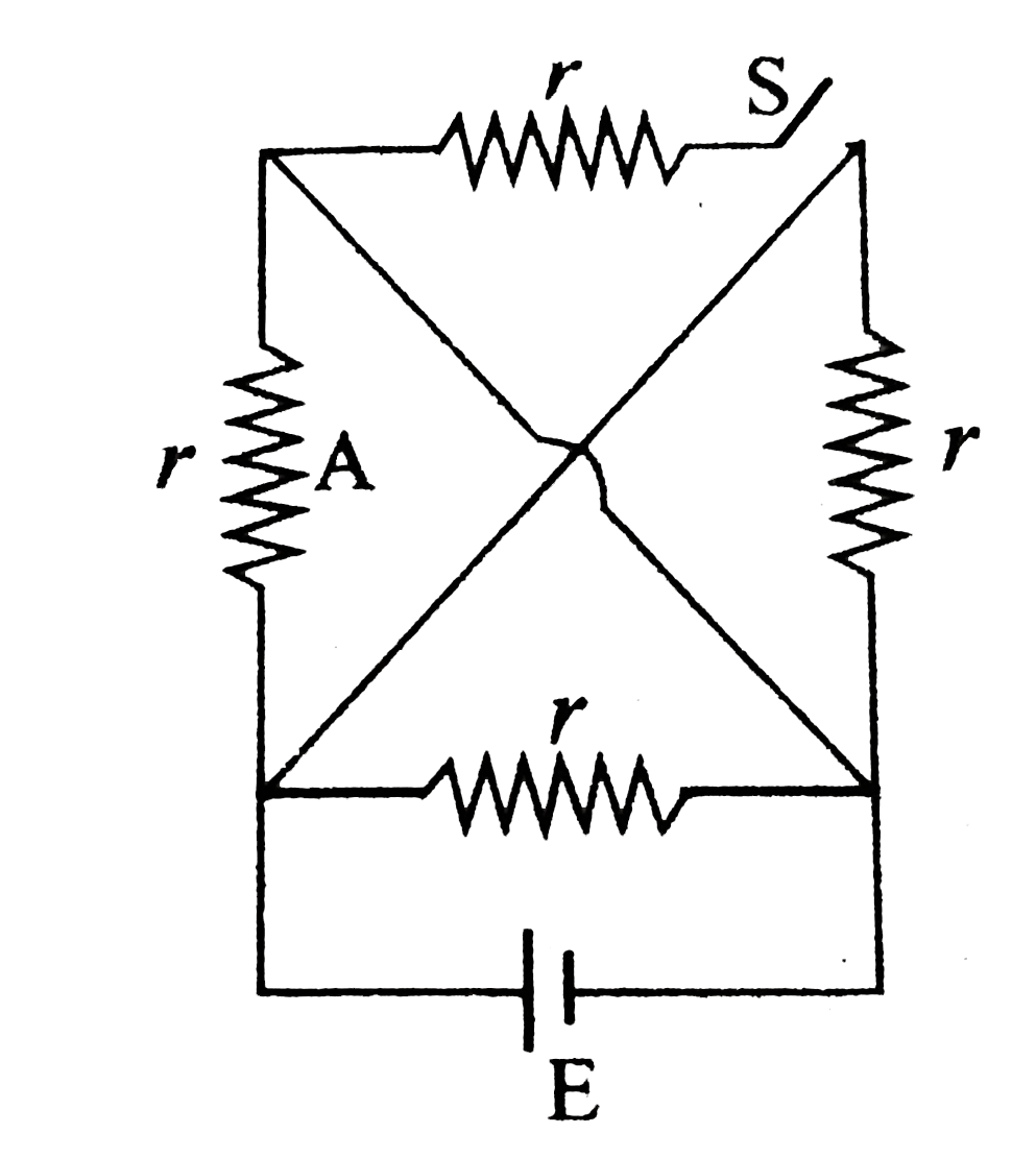
View SolutionIn the above question, what would have been the change in current in A if battery were some internal resistance.
View SolutionThe emf of a cell is `epsilon` and its internal resistance is r. its termnals are cannected to a resistance R. The potential difference between the terminals is `1.6V for R = 4 Omega, and 1.8 V for R = 9 Omega. Then,
View SolutionN identical calls are cannected to from a battery. When the terminals of the battery are joined directly. When the terminals of the battery are joined directly (short - ciruited), current I flows in the circuit. To obtain the maximum value of I,
View Solutionn identical cells, each of emf `epsilon` and internal resistance r, are joined in series to form a closed circuit. One cell A is joined with reversed polarity. The potential difference across any one cell is
View Solutionn identical cells, each of emf `epsilon` and internal resistance r, are joined in series to from a closed circuit. One cell A is joined with reversed polarity. The potential difference across each cell, except A, is
View SolutionA potential divider is used to given outputs of 2V and 3V form a 5V source, as shown in fig.
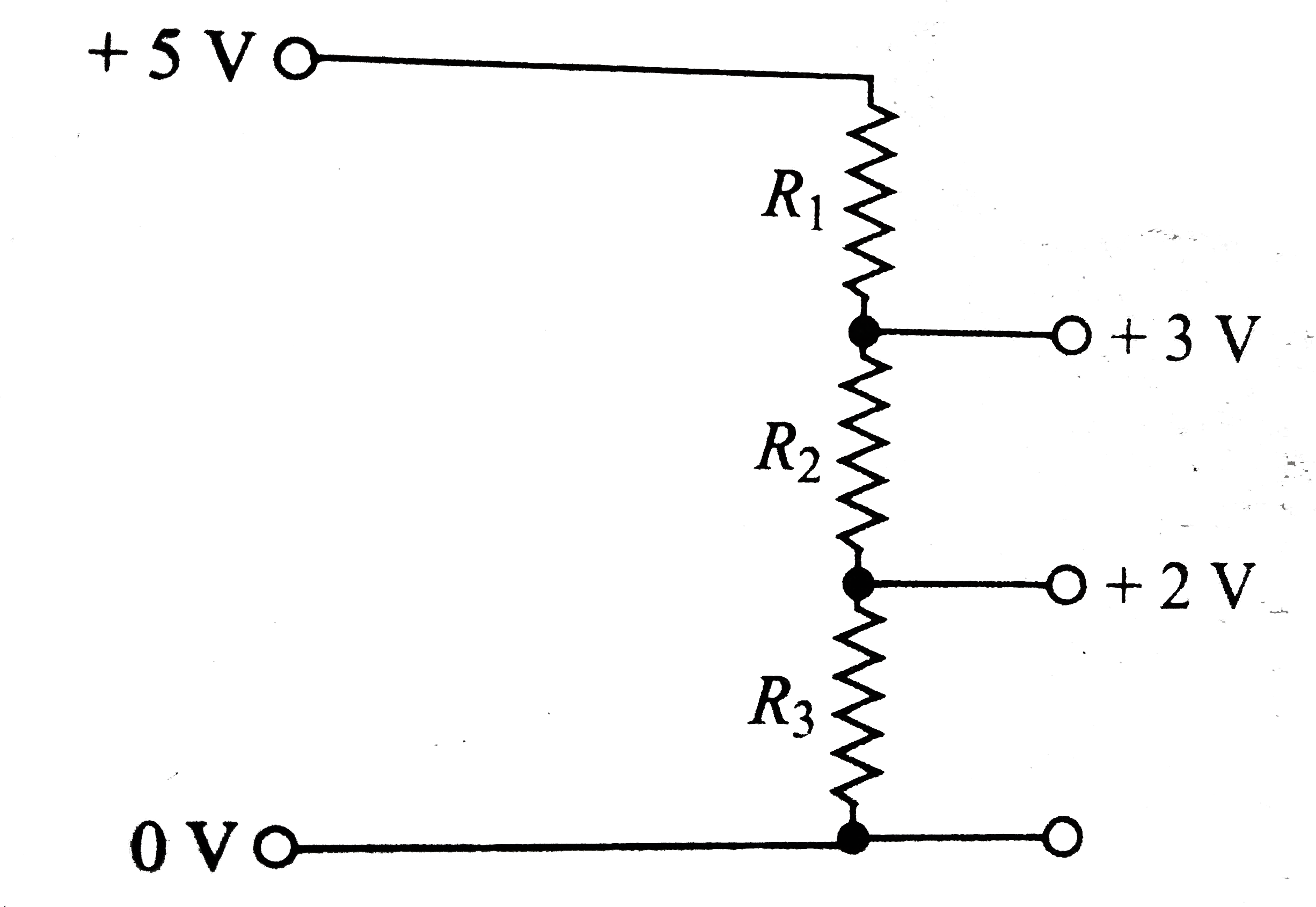
Which combination of resistance `R_1, R_2, and R_3` gives the correct voltages?
View SolutionFive resistors are connected between points A and B as shown in fig. A current of 10A flows from A to B. which of the following is correct?

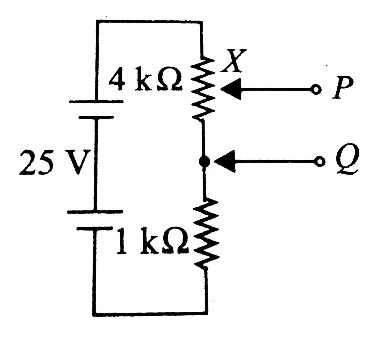
View SolutionShows a potential divider circuit, which, by adjusctment of the position of the contact X, can be used to provide a variable potential difference betweenn the terminals P and Q. what are the limits of this potential difference?
View SolutionThe current through the `8Omega` resistor (shown in fig.) is
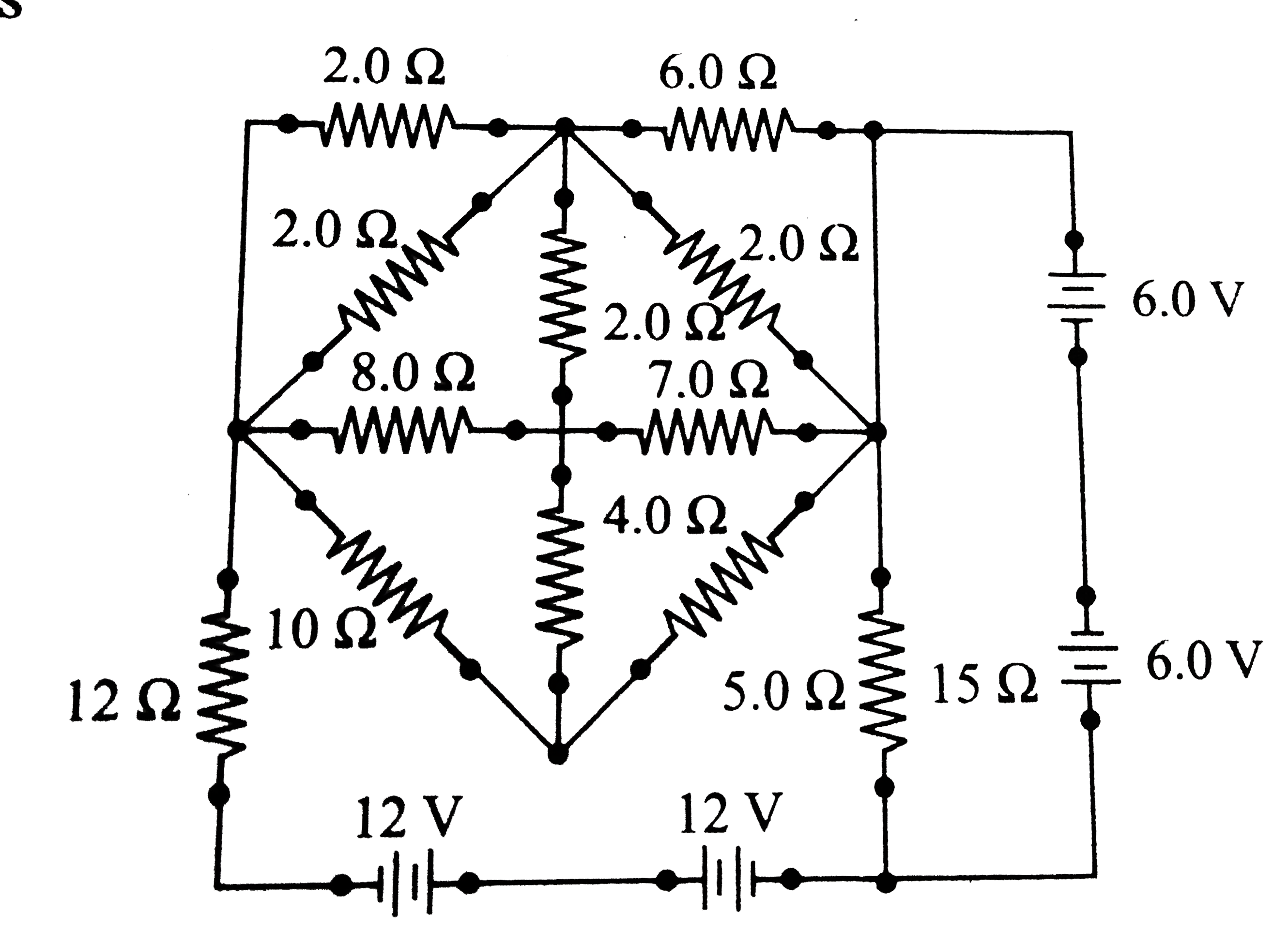
View SolutionIn the network shown in fig. , the potential differene across A and B is
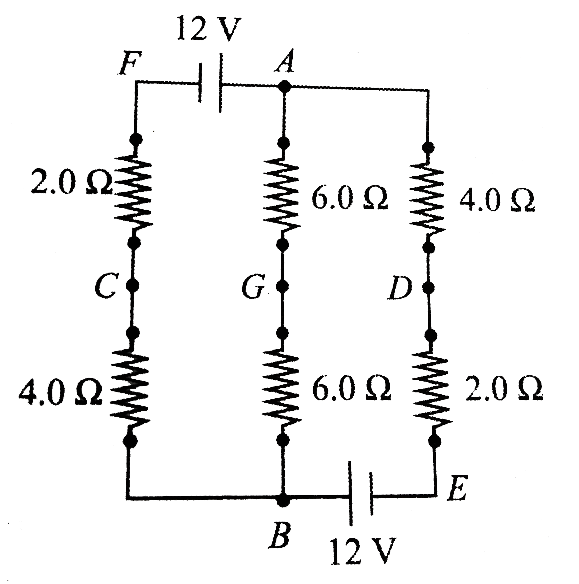
View SolutionWhat resistor should be connected in parallel with the `20Omega` resistor in branch ADC in the circuit shown in fig. so that potential difference between B and D may be zero ?
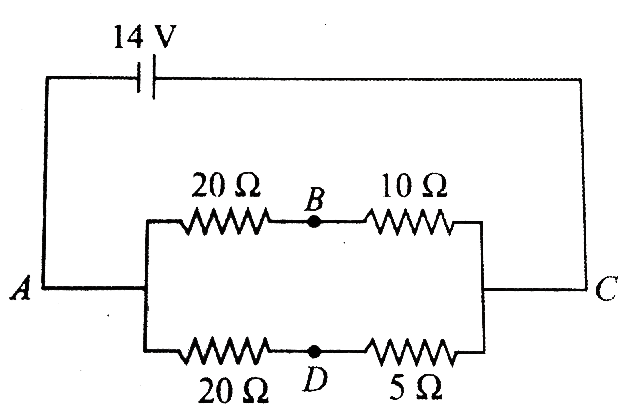
View SolutionFind out the value of resistance R in fig.
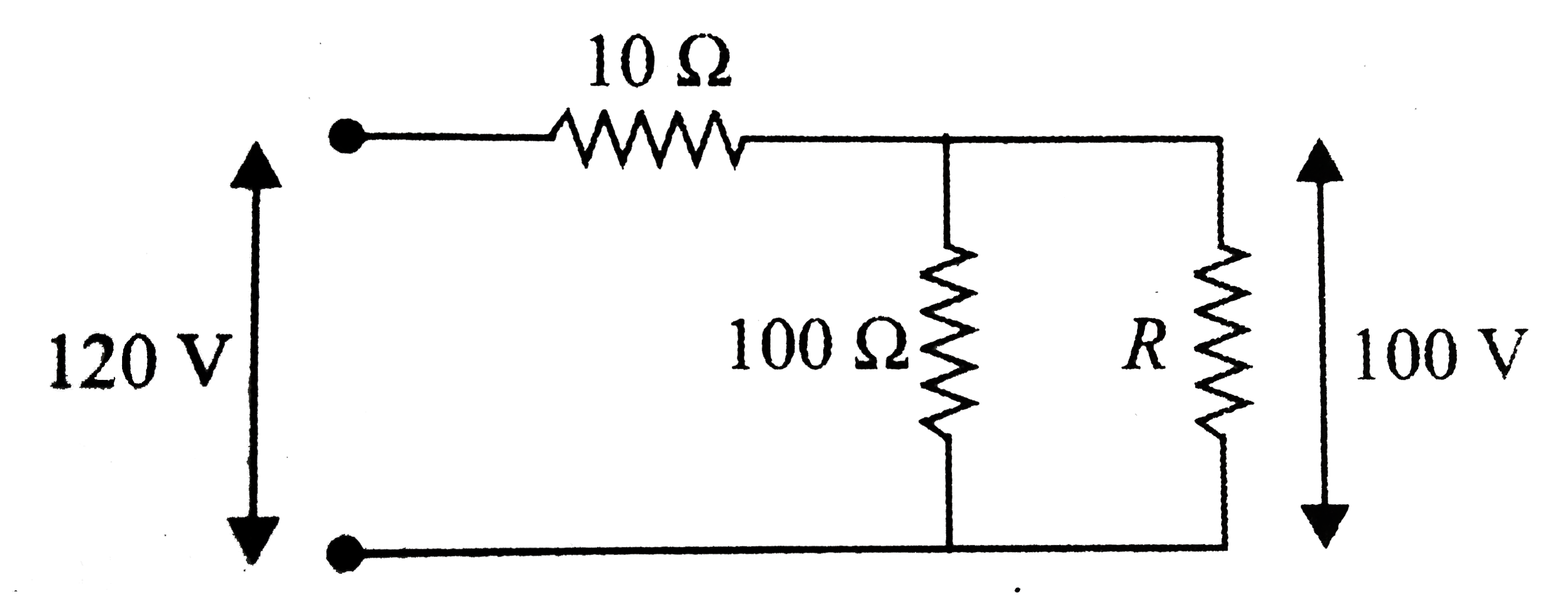
View SolutionIn the figure, the value of resistors to be connected between `C` and `D` so that the resistance of the entire circuit between `A` and `B` does not change with the number of elementary set used is
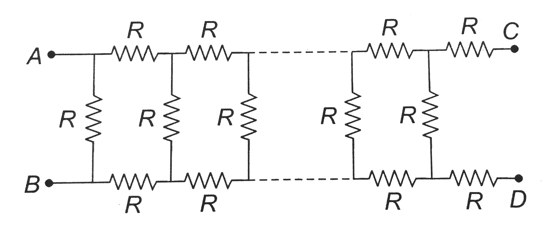
View SolutionA wire of length L and 3 identical cells of negligible internal resistance are connected in series. Due to the current, the temperature of the wire is raised by `DeltaT` in a time t. A number N of similar cells is now connected in series with a wire of the same material and cross-section but of length 2L. The temperature of the wire is raised by the same amount `DeltaT` in the same time t. the value of N is
View SolutionShows a Wheatstone bridge circuit. Which of the following correctly showsk the currents `I_1, I_2 and I_3` in the decreasing order of magnitude?
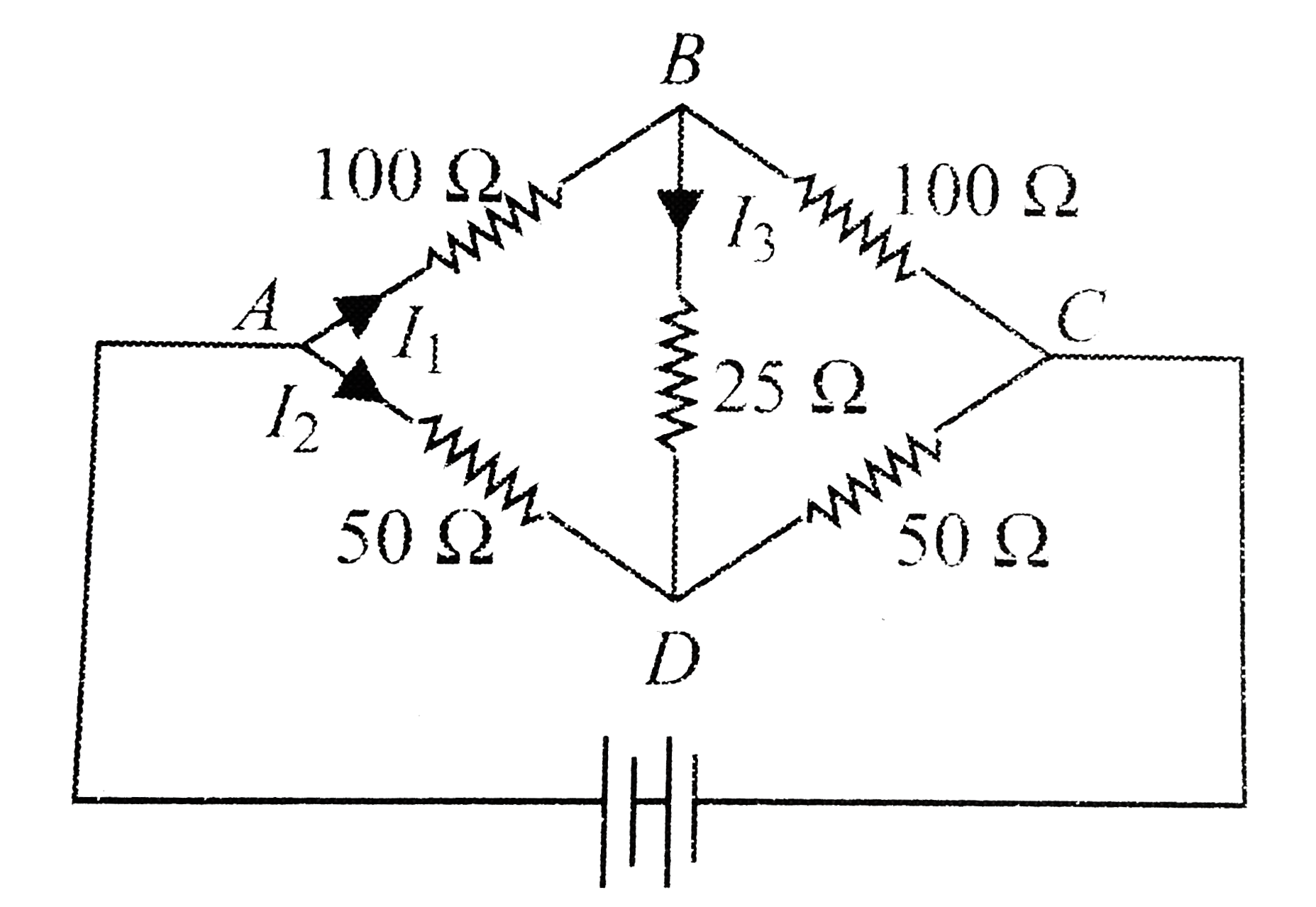
View SolutionFor a cell, a graph is plotted between the potential difference `V` across the terminals of the cell and the current `I` drawn the cell. The emf and the internal resistance of the cell are `E` and `r`, respectively. Then
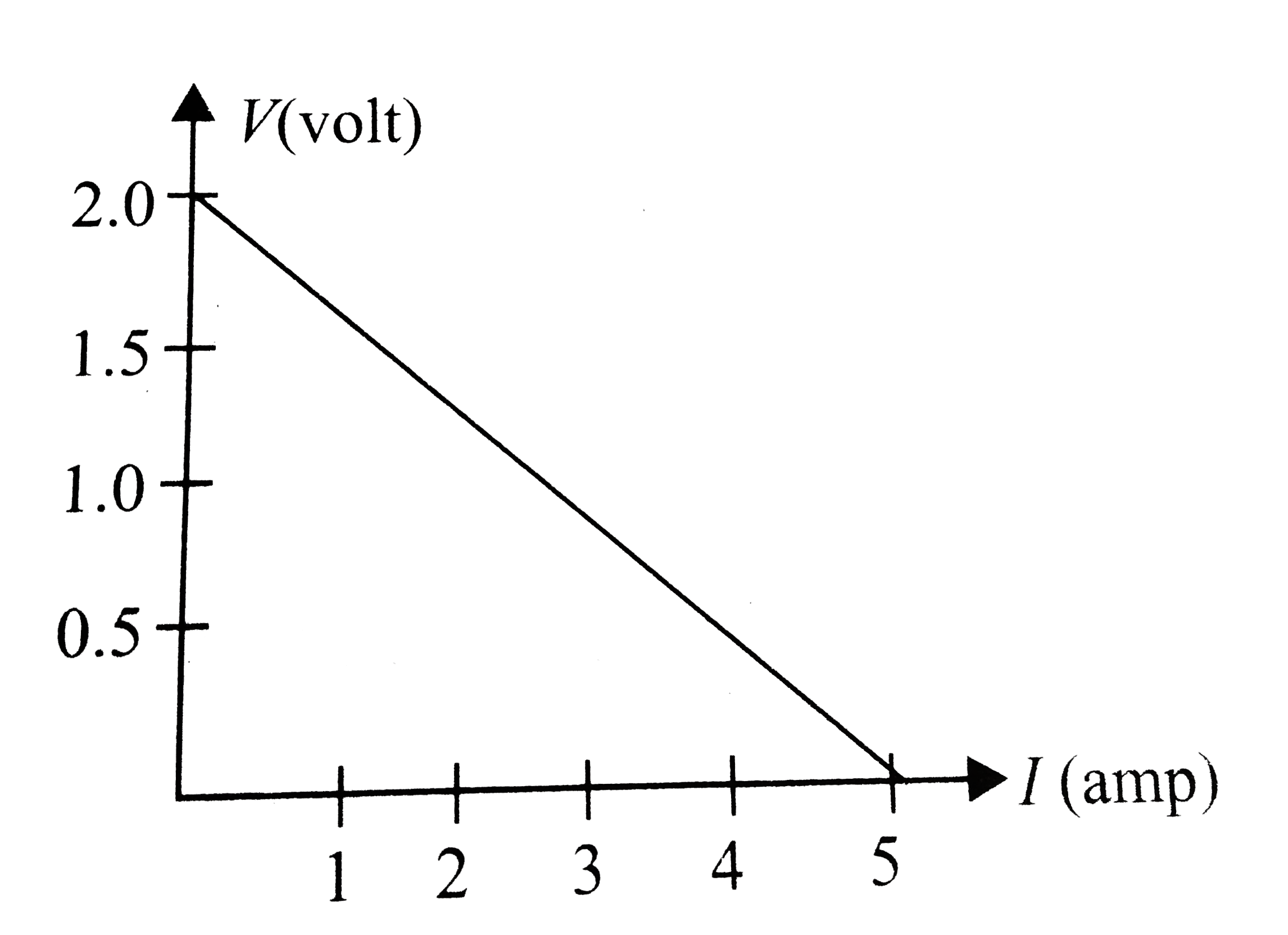
View SolutionIn the given circuit, with steady current, the potential drop across the capacitor must be
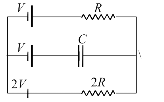
View SolutionFor the arrangement shown in the switch is closed at t =0. The time after which the current becomes `2.5muAS` is given by (take in 2 =0.69)
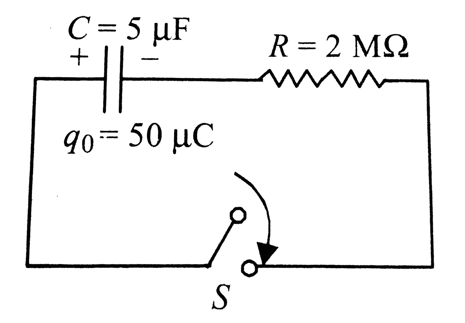
View SolutionA capacitor discharges through a resistance. The stored energy `U_0` in one capacitive time constant falls to
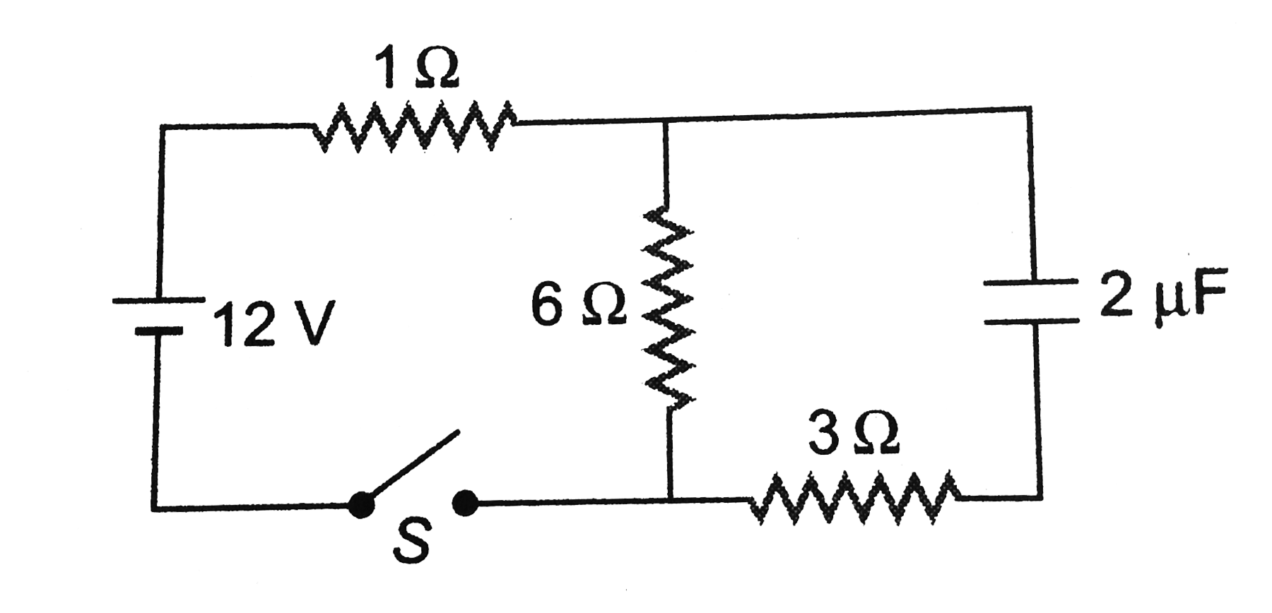
View SolutionWhen the switch is closed, the initial current through the `1Omega` resistor is
 `
`
View SolutionA capacitor C is connected to the two equal resistances as shown in fig. What is the ratio of the time constant during charging and discharging of the capacitance?
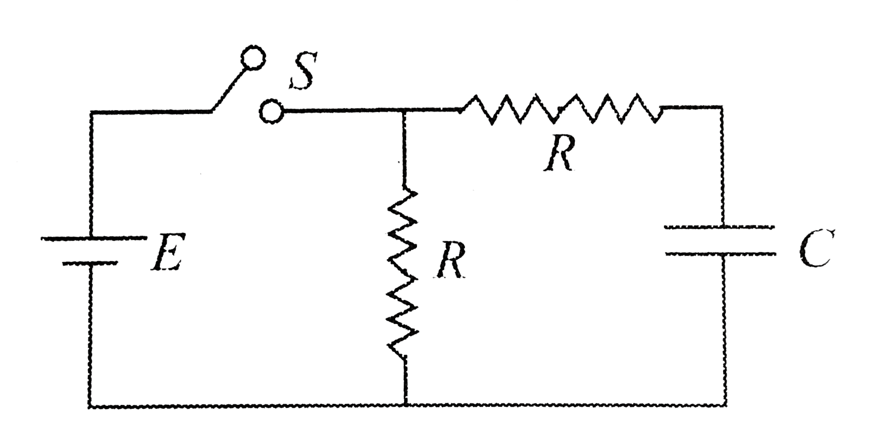
View SolutionCurrent through the battery at the instance when the switch S is closed is
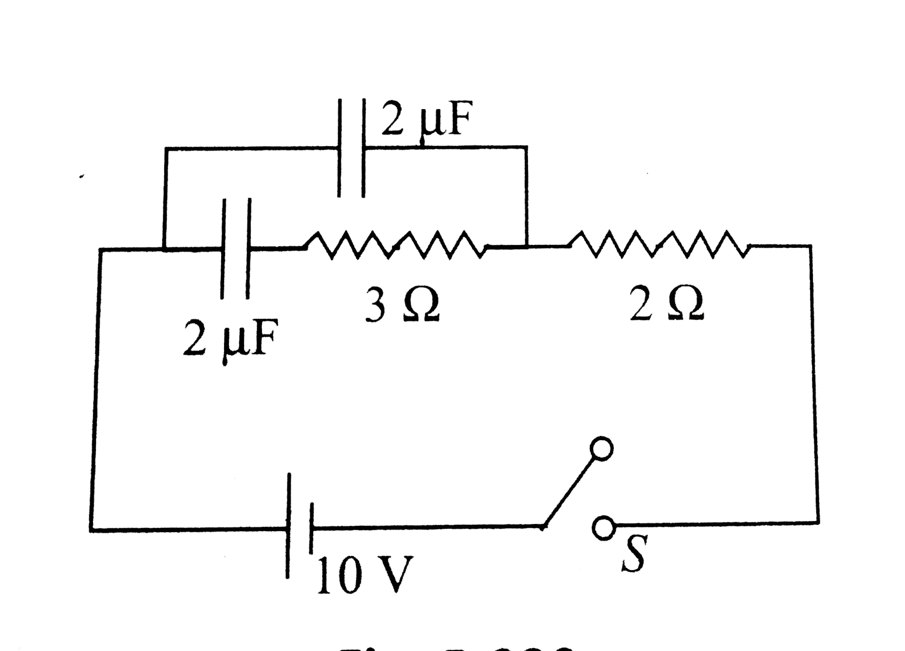
View SolutionThe equivalent resistance between A and B in fig. at steady state will be
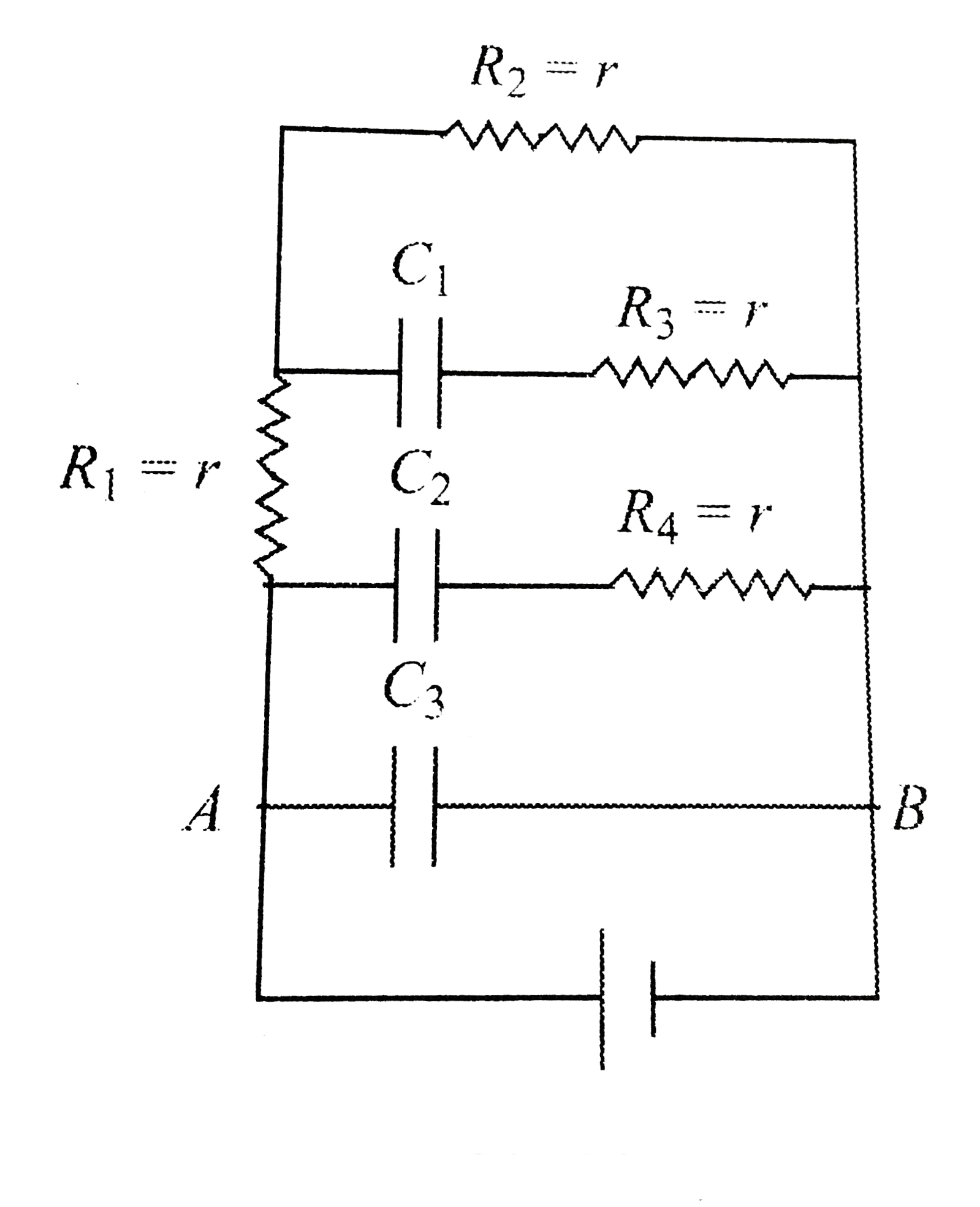
View SolutionIn the circuit shown in fig. when the switch is closed, the capacitor charges with a time constant
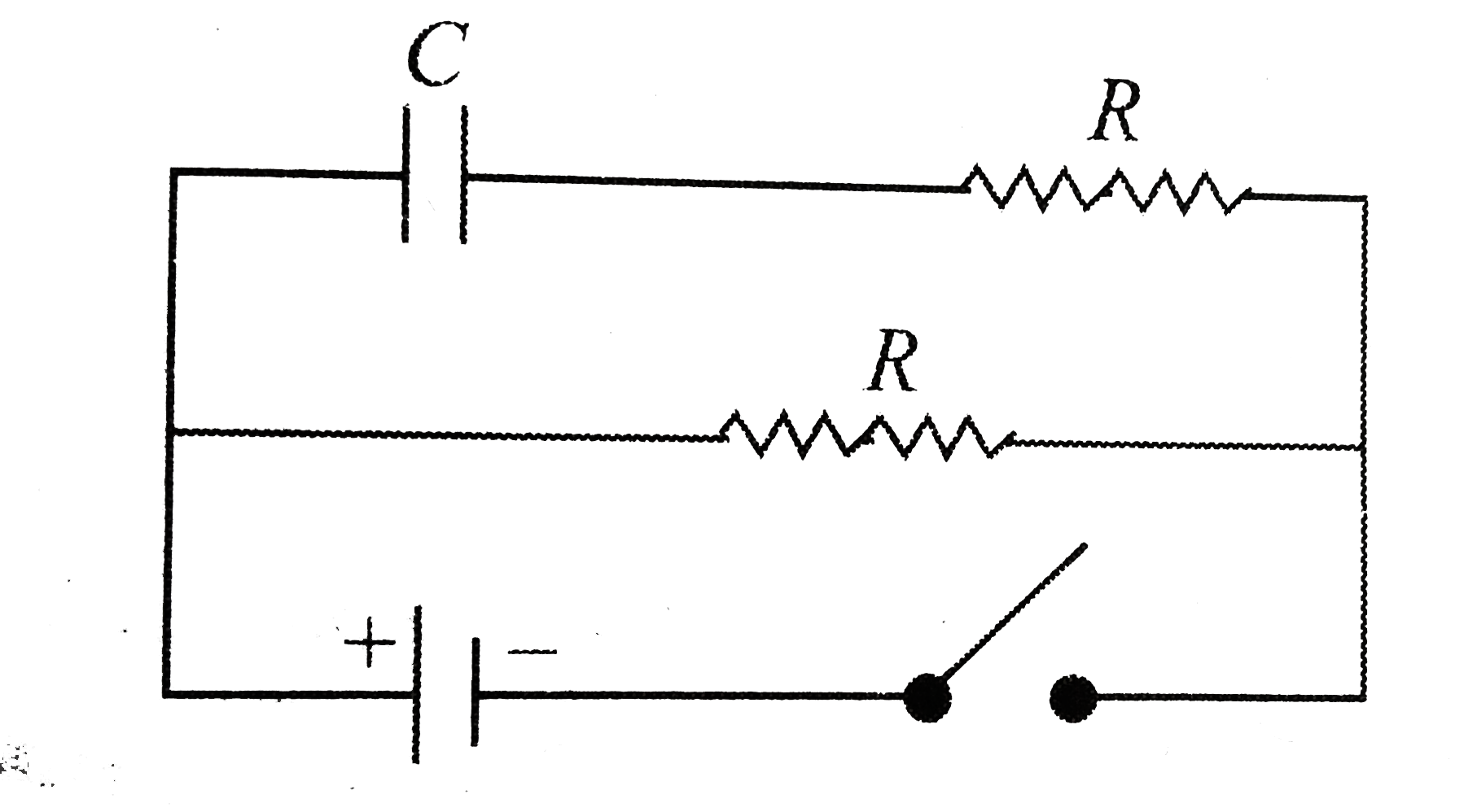
View SolutionIn the question 42, if the switch is opened after the capacitor has been charged, it will discharge with a time constant
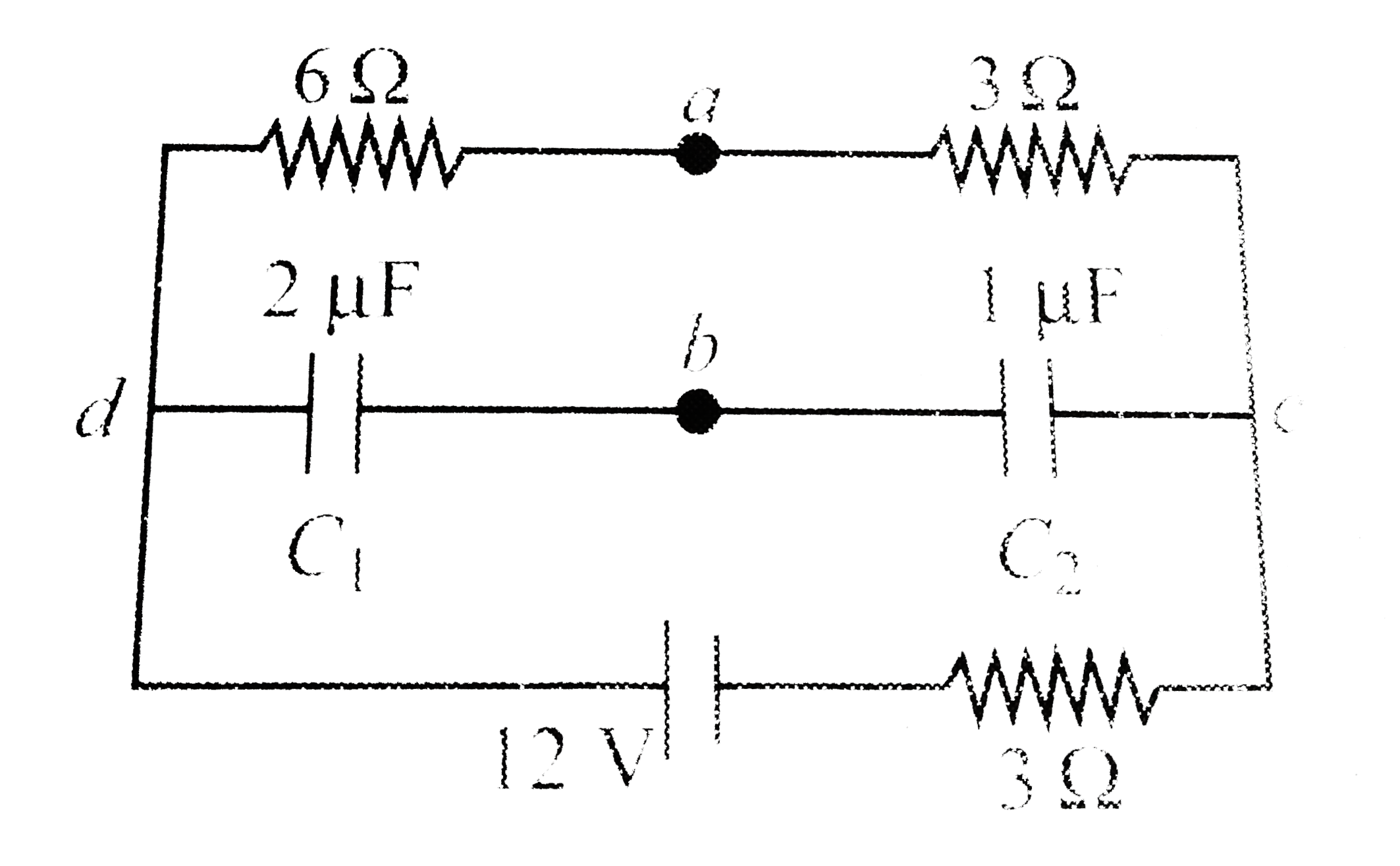
View Solutionwhat is the charge stored on each capacitor `C_1 and C_2` in the circuit shown in fig.
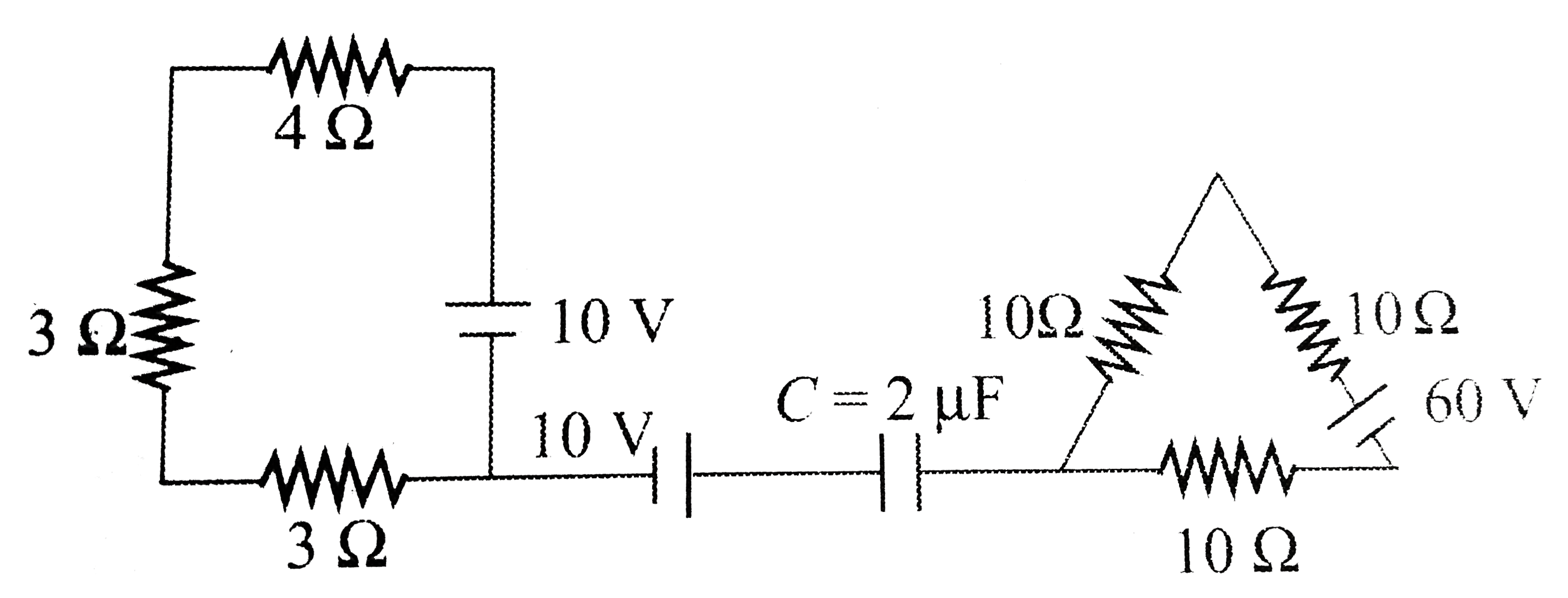
View SolutionIn the circuit shown in fig. find the maximum energy stored on the capacitor. Initially, the capacitor was uncharged.
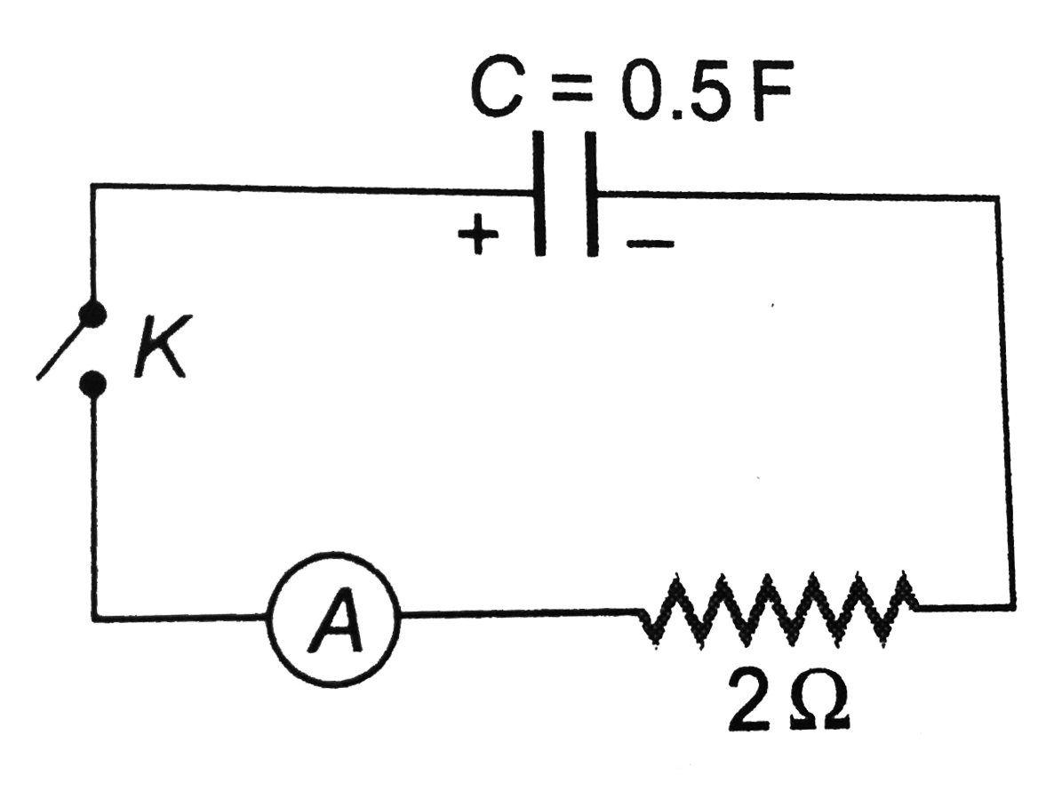
View SolutionA charged capacitor is allowed to discharge through a resistor by closing the key at the instant `t=0`. At the instant `t=(ln 4)mus`, the reading of the ammeter falls half the initial value. The resistance of the ammeter is equal to
View SolutionIn the circuit shwon in fig. switch S is closed at time t = 0. Let `I_1 and I_2` be the currents at any finite time t, then the ratio `I_1// I_2`
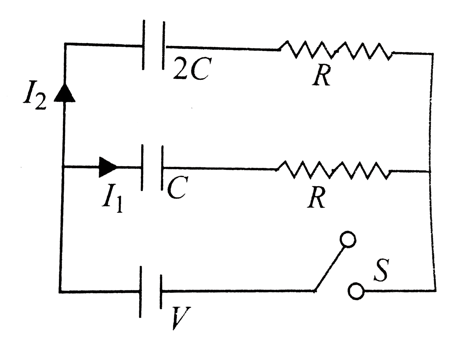
View SolutionIn the circuit shown in fig. `C_1 = 2C_2` Initially, capacitor `C_1` is charged to a potential of V. The current in the circuit just after the switch S is closed is
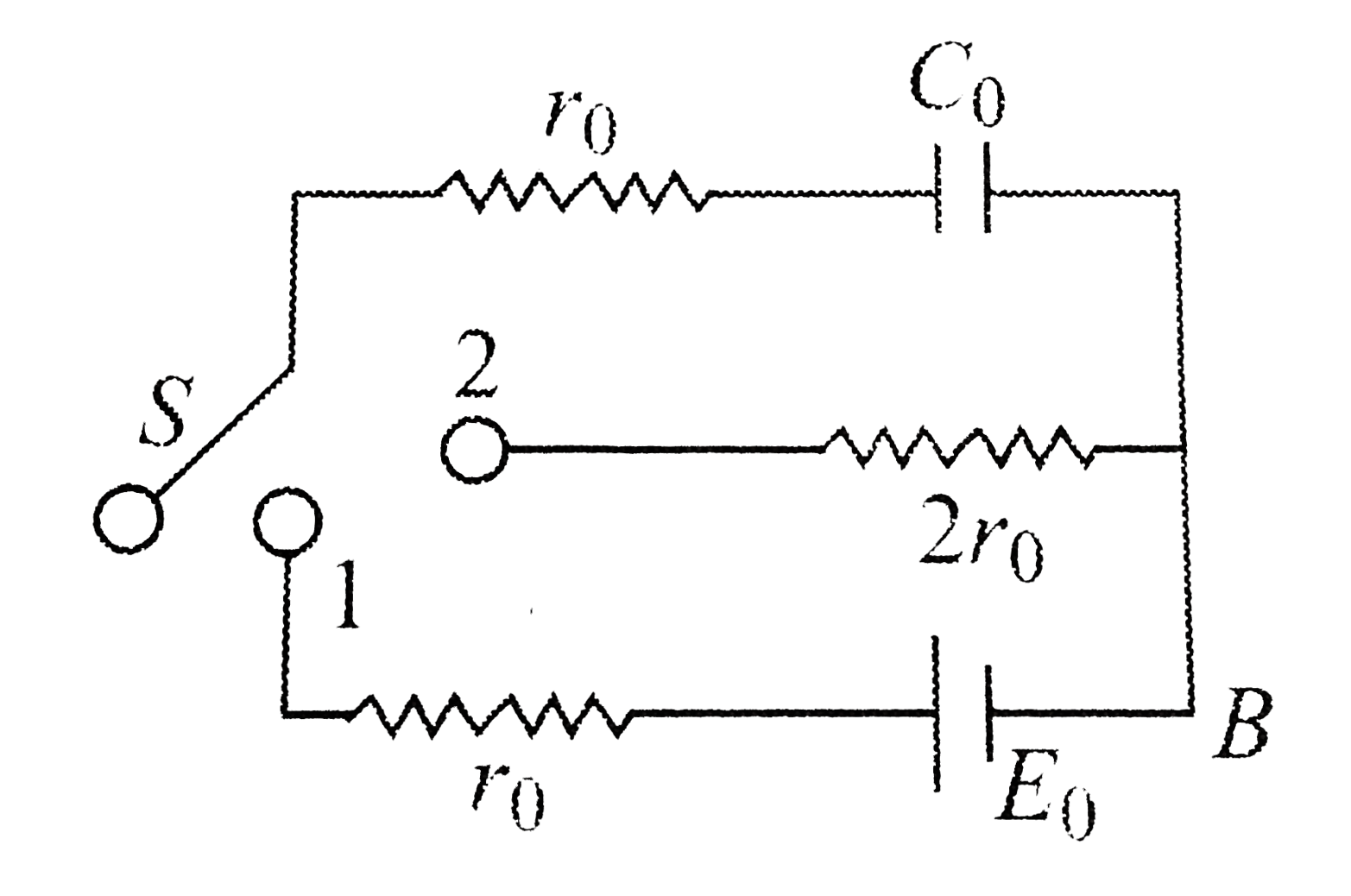
View SolutionIn the circuit given in fig. swithc S is at position 1 for long time. Find the total heat generated in resistor of resistance `(2r_0),` when the switch S is shifted from position 1 to position 2.
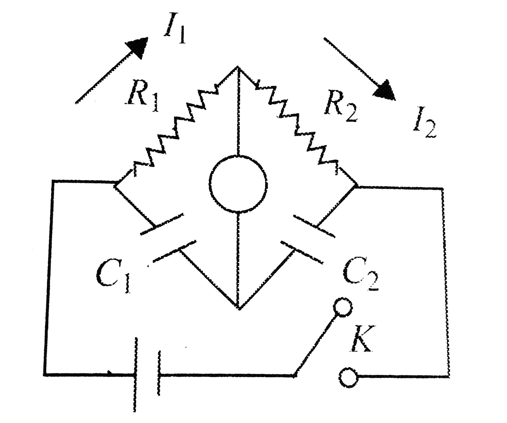
View SolutionIn the circuit in fig. If no current flows through the galvanometer when the key k is closed, the bridge is balanced. The balancing condition for bridge is
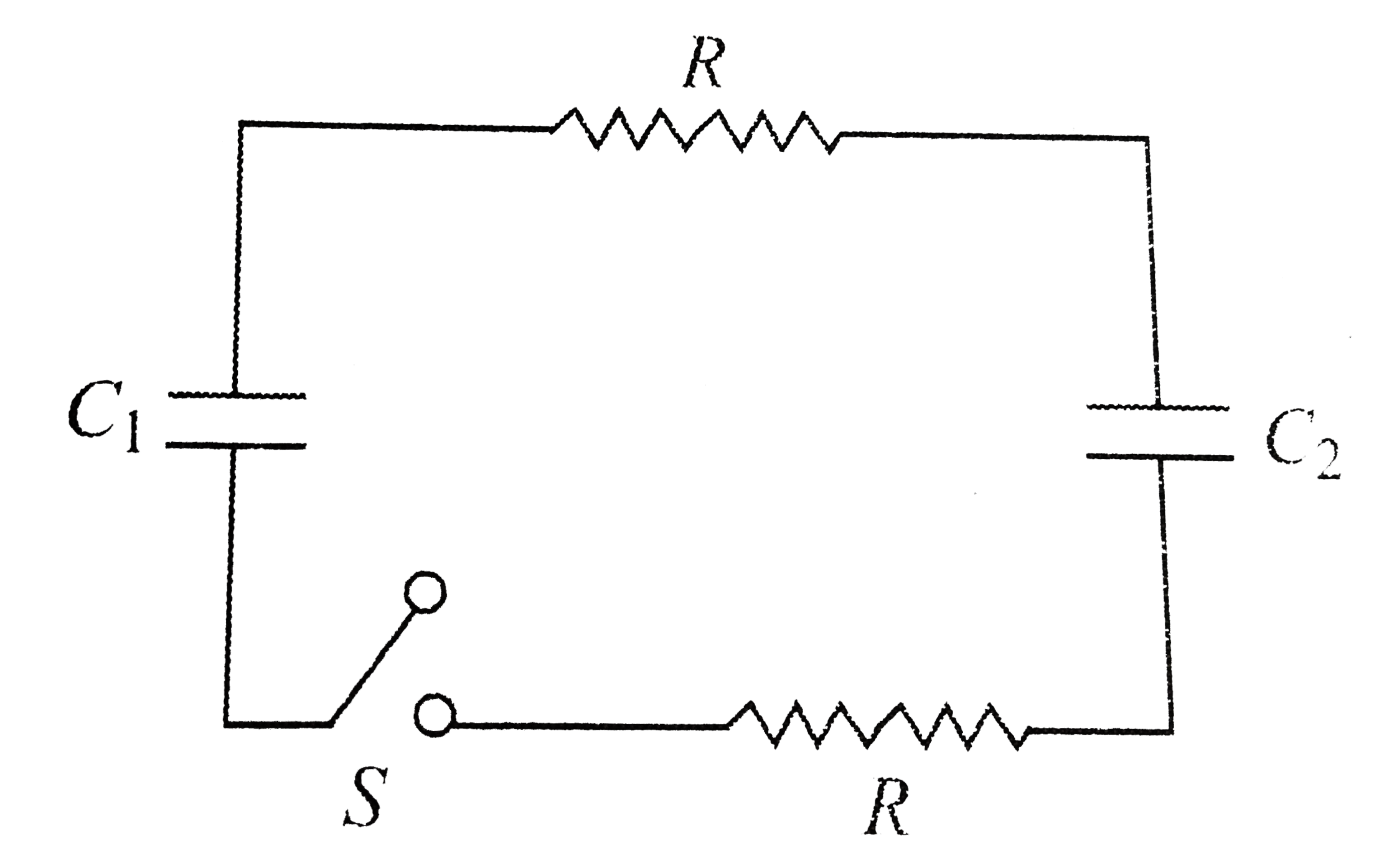
View SolutionA capacitor of capacitance C has charge Q. it is connected to an identical capacitor through a resistance. The heat produced in the resistance is
View SolutionIn the circuit shown in fig. the cell is ideal with emf 15V. Each resistance is of `3Omega.` The potential difference across the capacitoro in steady state is
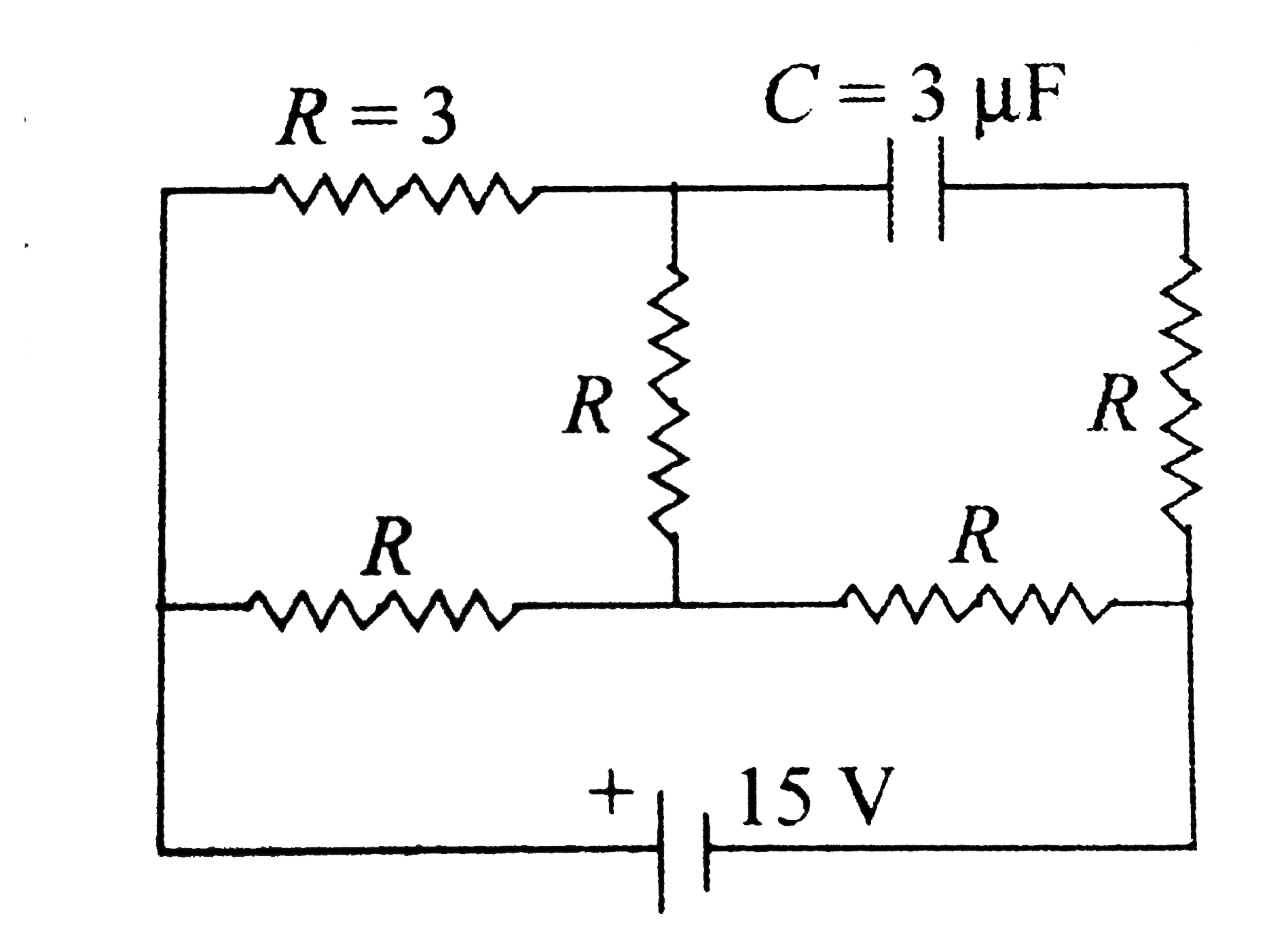
View SolutionThe temperature coefficient of resistance of conductor varies as `alpha(T) = 3T^2 +2T.` If `R_0` is resistance at T = 0and R is resistance at T, then
View SolutionA straight conductor of uniform cross section carries a time varying current, which varies at the rate dI//dt = I. If s is the specific charge that is carried by each charge carries of the conductor and l is the length of the condcutor, then the totalt force experienced by all the charge carries per unit length of the conductor due to their drift velocities only is
View SolutionSixteen resistor, each resistane `16 Omega` are connected in the circuit as shown in fig. the net resistance between A and B is
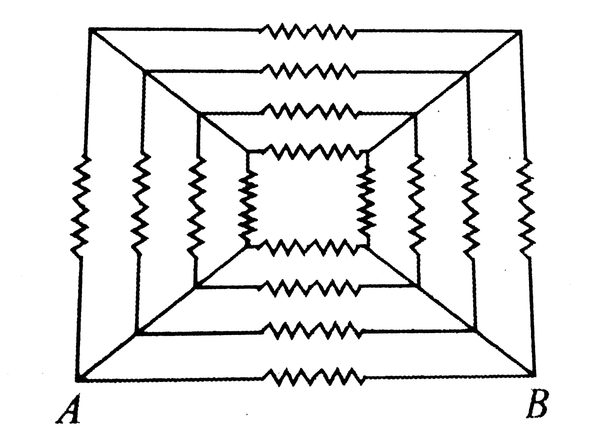
View SolutionThe circuit diagram shown in the figure consist of a large number of elements (each element has two resistors `R_1 and R_2`). The resistance of the resistors in each subsequent element differs by a factor of `k= 1/2` from the resistance of the resistors in previous elements. Find the equivalent resistance between A and B.

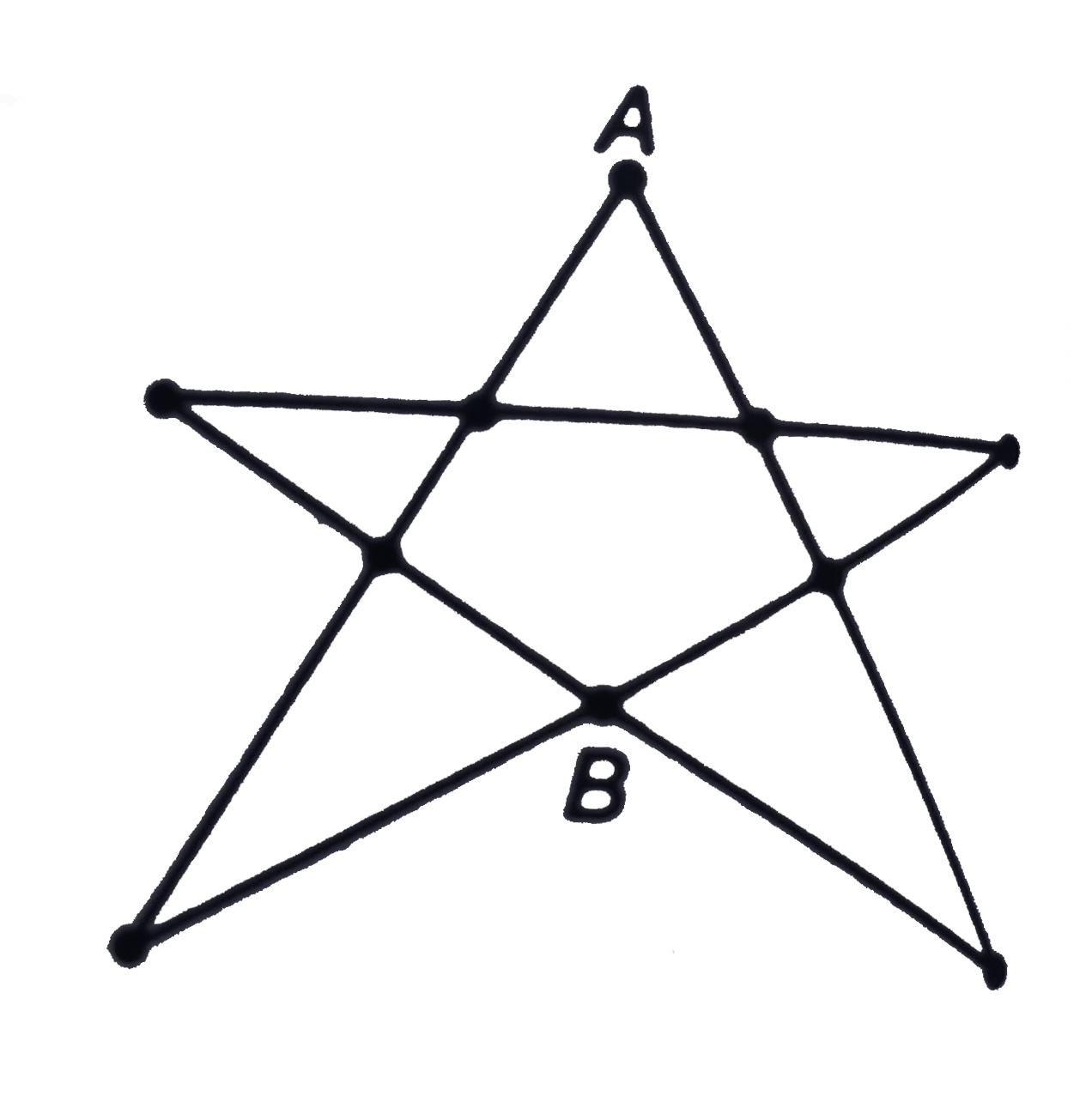
View SolutionThe resistance of all the wires between any two adjacent dots is `R`. Then, equivalent resistance between `A `and `B` as shown in figure is
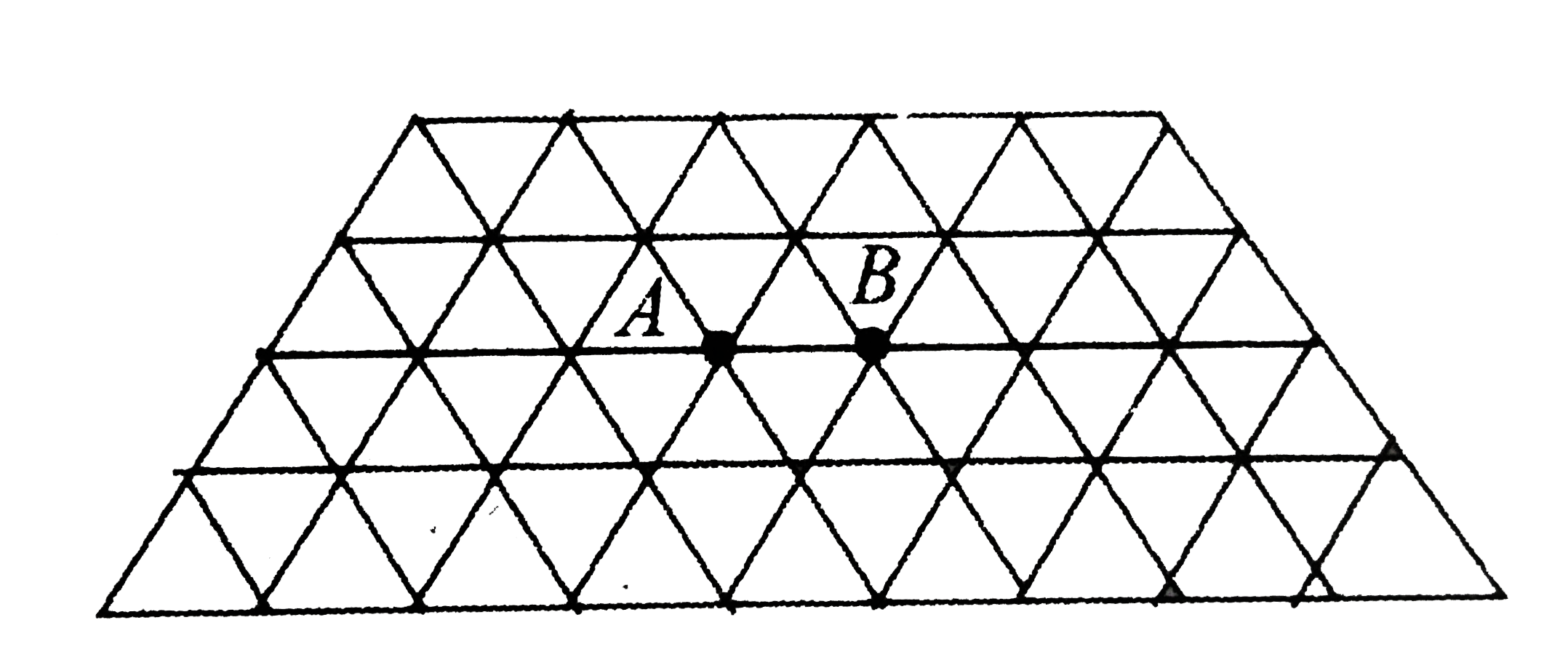
View SolutionThere is an infinite wire grid with cells in the form of equilateral triangles. The resistance of each wire between neighboring joint connections is `R_0` The net resistance of the whole grid between the points A and B as shown in fig.
View SolutionFor the circuit shown in fig. the equivalent resistance between A and C is
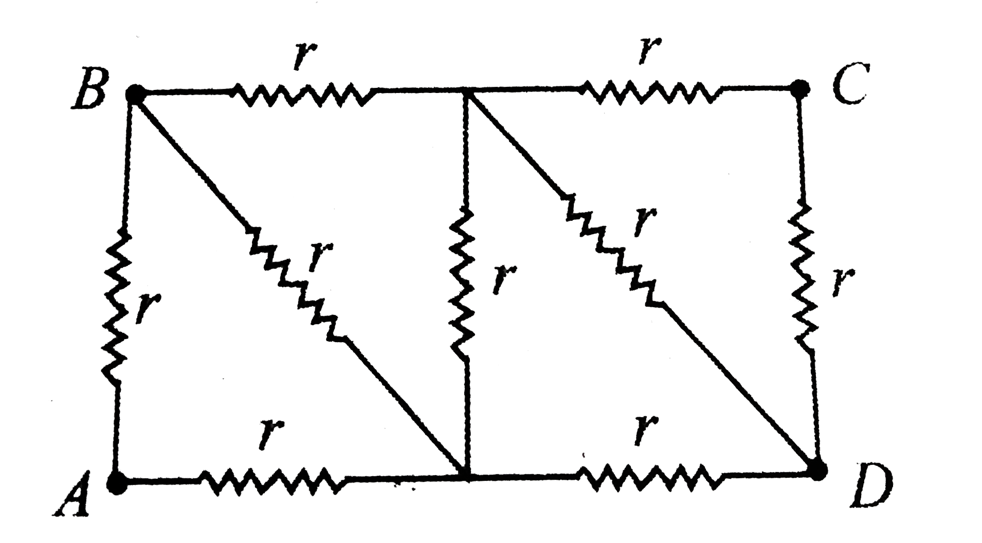
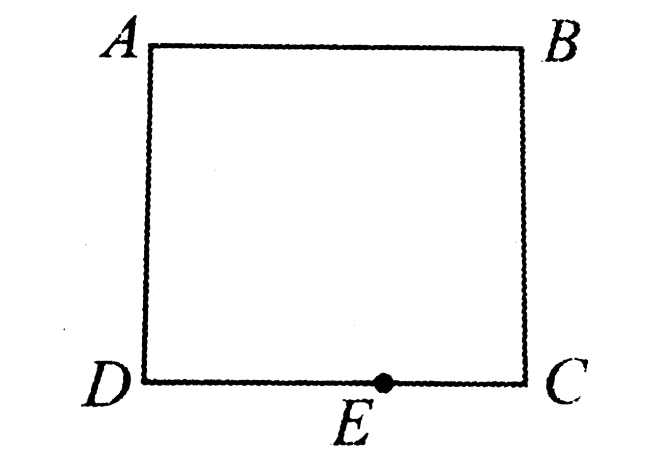
View SolutionABCD is a square where each side is a uniform wire of resistance `1Omega.` A point E lies on CD such that if a uniform wire of resistance `1Omega` is connected across AE and constant potential difference is applied across A and C, then B and E are equipotential.
View SolutionA capacitor is charged to a certain potential and then allowed to discharge through a resistance R. The ratio of charge on the capacitor to current in the circuit
View SolutionTwo capacitors `C_1 and C_2 (C_1 gt C_2)` are charged separtately to same potential. Now they are allowed to discharge through similar resistors. Initial rate of discharging will be
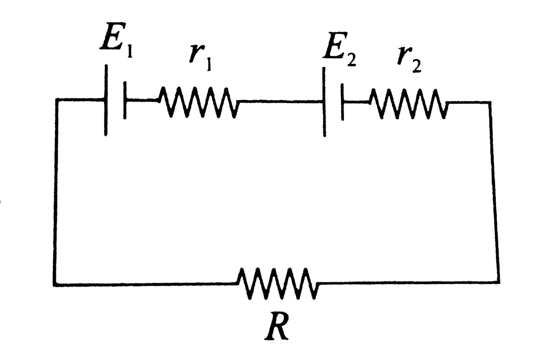
View SolutionUnder what condition, the current passing through the resistance R can be increased by short - circuiting the battery of emf `E_2` The internal resistances of the two batteries are `r_1 and r_2,` respectively.
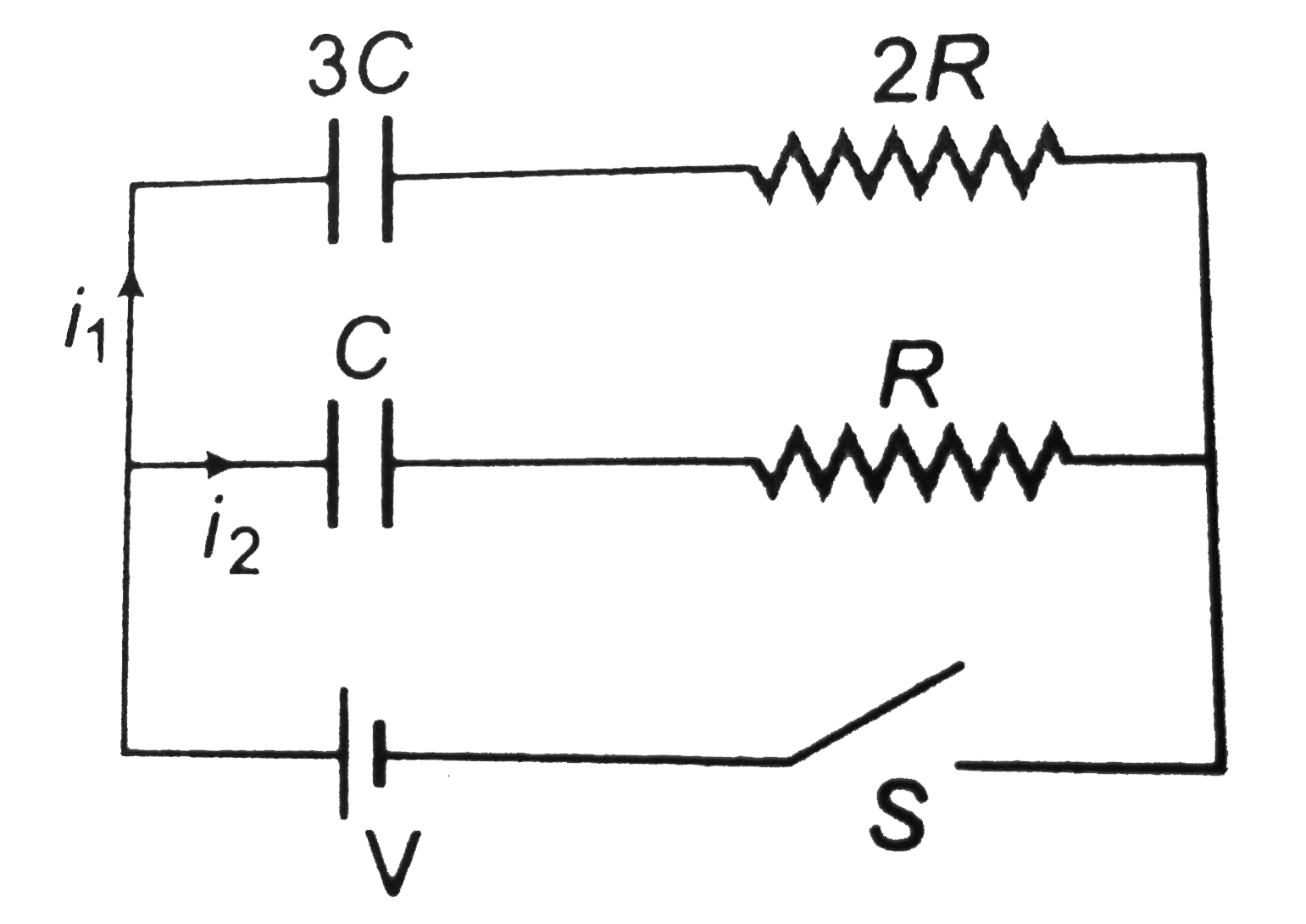
View SolutionIn the circuit shown switch `S` is closed at `t=0`. Let `i_1` and `i_2` be the current at any finite time t then the ratio `i_1/i_2`
View SolutionTo get maximum current through a resistance of `2.5Omega,` one can use m rows of cells, each row having n cells. The internal resistance of each cell is `0.5 Omega` what are the values of n and m, if the total number of cells is 45.
View SolutionIn the given circuit, with steady current, the potential of point A must be
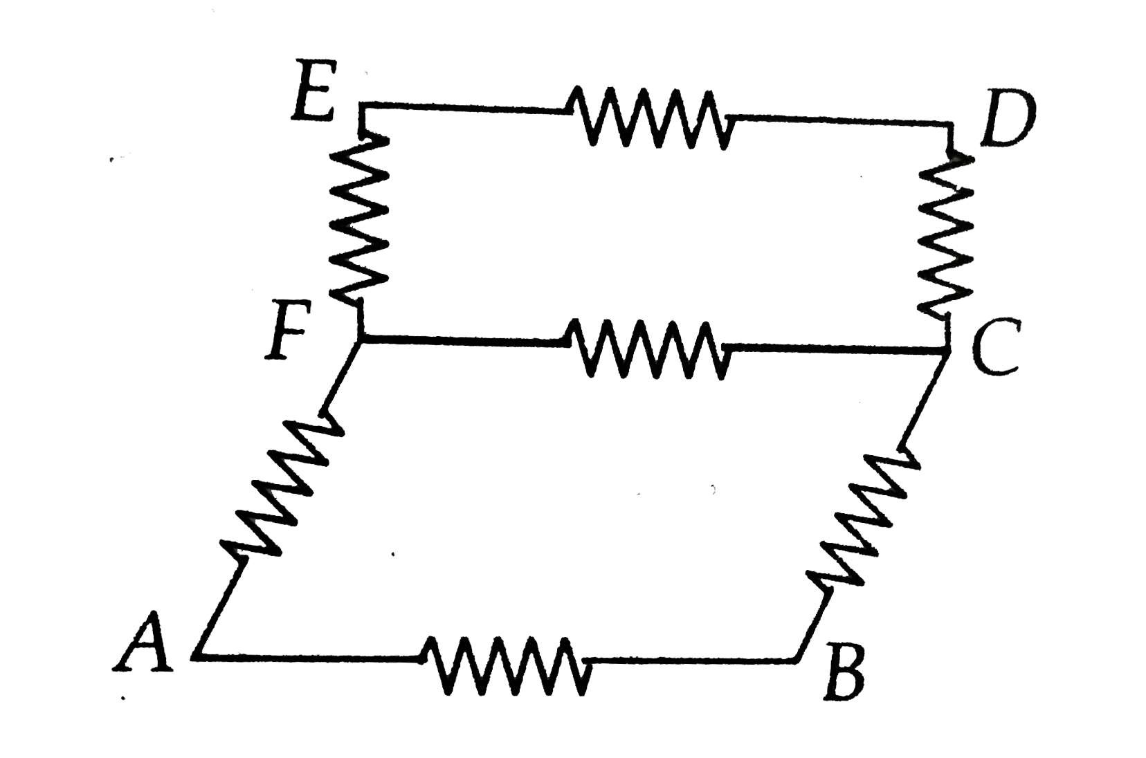
View SolutionIf the potential difference between A and D is V, what will be potential difference between F and C. each of the resistance is R.
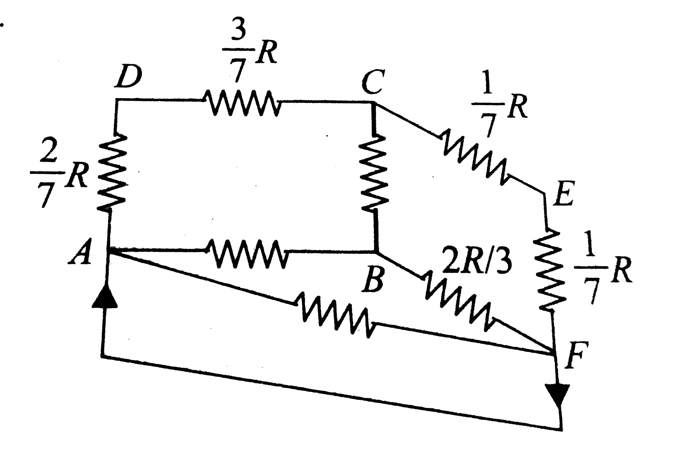
View SolutionThe current enters at A and leaves at F. The values of some resistance are shown. What should be the value of resistance AB so that no current will flow through CB?
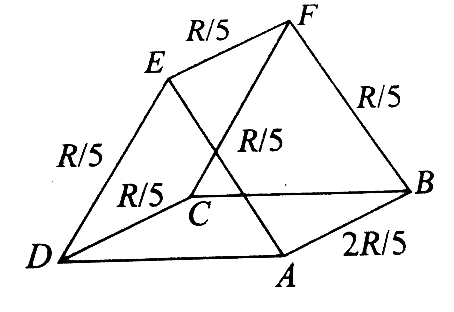
View SolutionThe current enters at A and comes out at D. Some of the resistance are shown. What should be resistance of wire CB so that it draws double of the current that enters the wire BF.
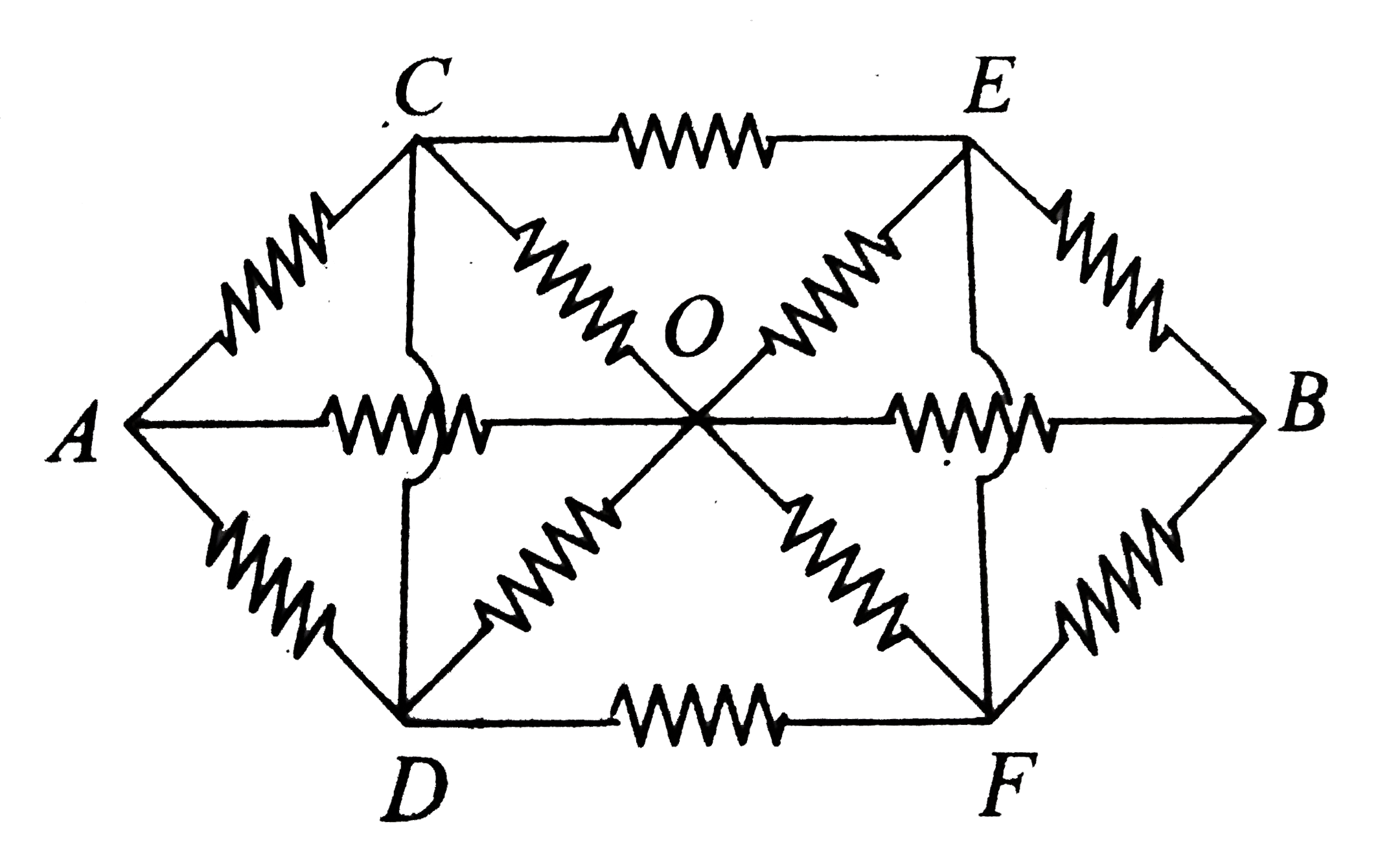
View SolutionFind the equivalent resistance between A and B. Each resistor has same resistance R.
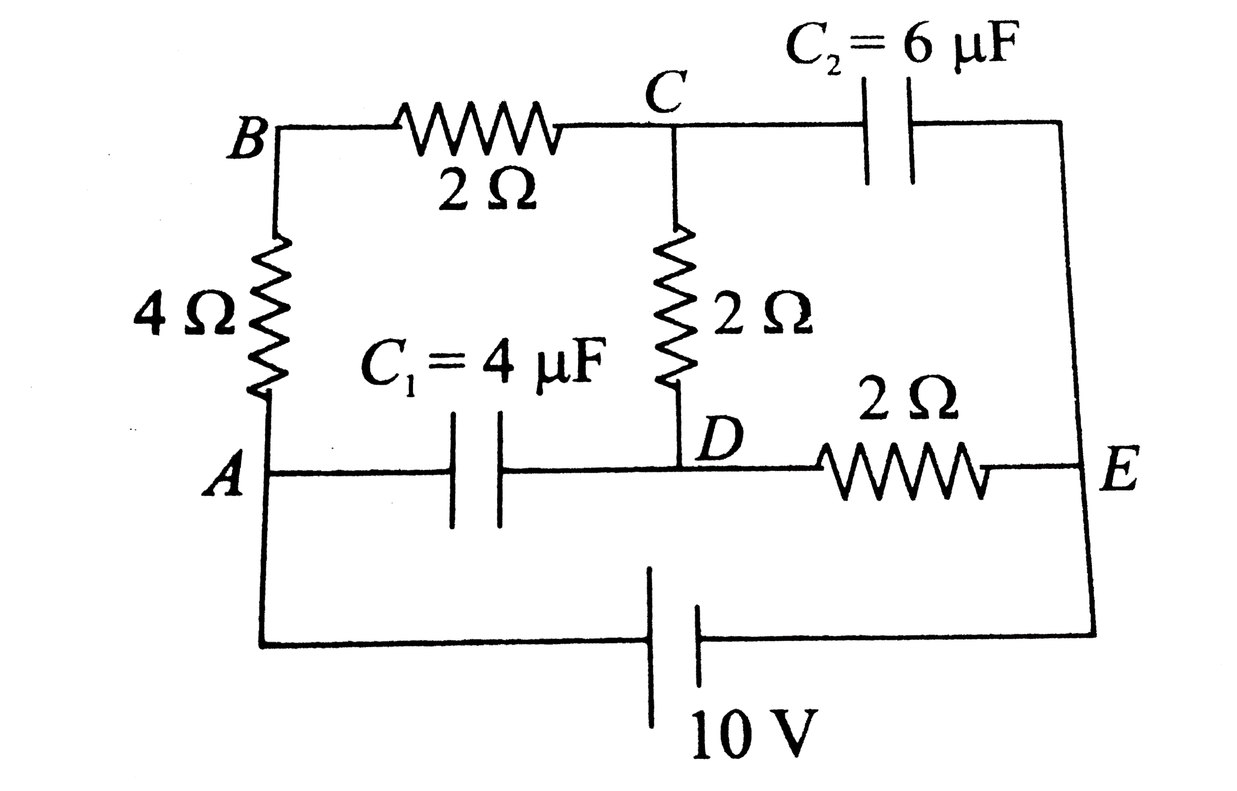
View SolutionFind the potential difference across `C_2.`
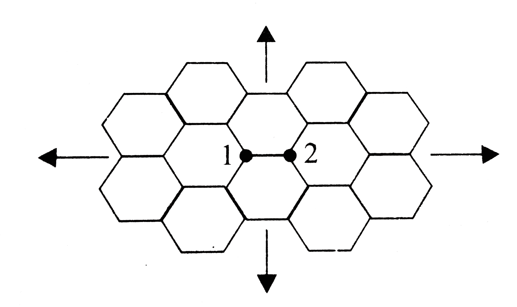
View SolutionThe given infinite grid consists of hexagonal cells of six resistors each of resistance R. then `R_(12)`
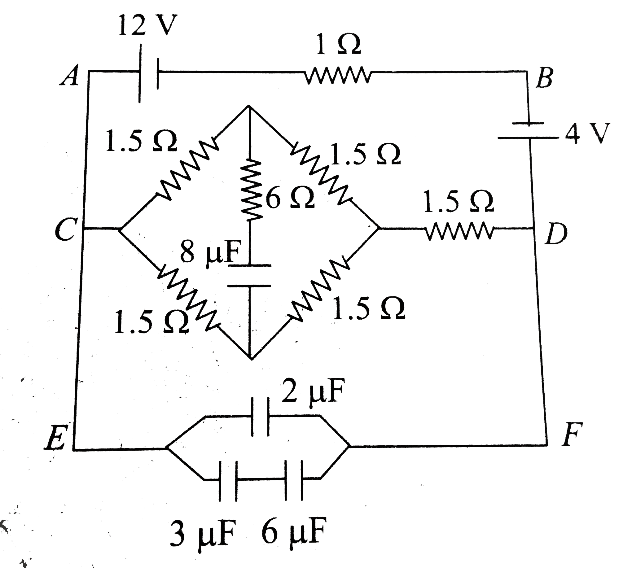
View SolutionIn the given circuit, find the potential differece across the `6muf` capacitor in steady state.
View Solution
Single Correct questions and complete solutions for chapter ELECTRIC CURRENT AND CIRCUIT of CENGAGE PHYSICS (HINGLISH) of Class 12