Complete Solutions to Single Correct of chapter MISCELLANEOUS VOLUME 5 of Class 12 book with complete answers and questions
| Class 12 | PHYSICS |
| Chapter | MISCELLANEOUS VOLUME 5 |
| CENGAGE PHYSICS | Single Correct |
| Number Of Questions | 100 |
| Academic Year | 2023-24 |
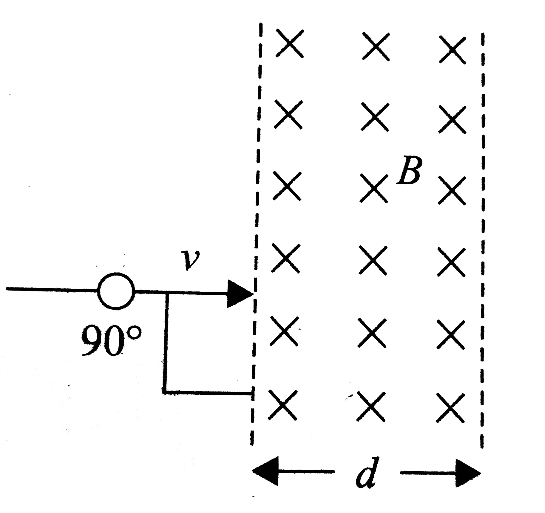
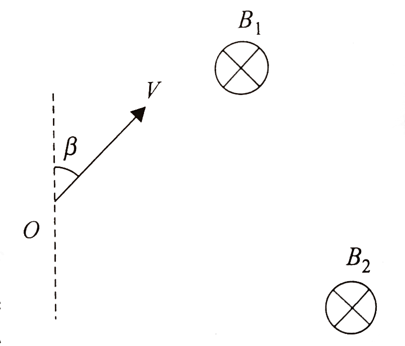
A positive charge particle of mass m and charge q is projected with velocity v as shown in Fig. If radius of curvature of charge particle in magnetic field region is greater than d, then find the time spent by the charge particle in magnetic field.
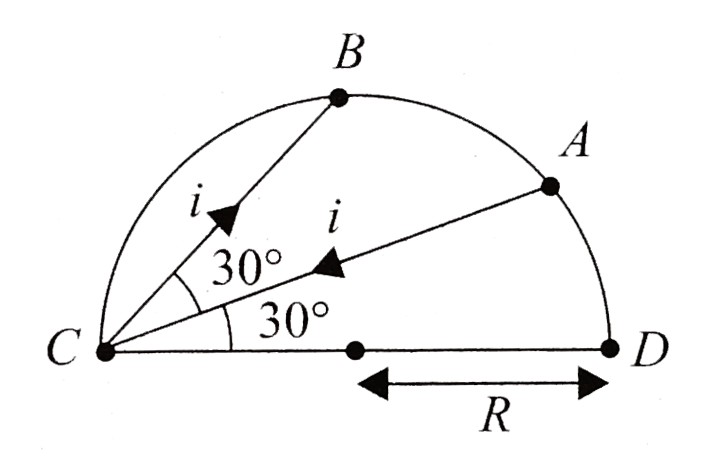
View SolutionA current carrying wire is placed in the grooves of an insulating semicircular disc of radius 'R', as shown in Fig. The current enters at point A and leaves from point B. Determine the magnetic field at Point D.
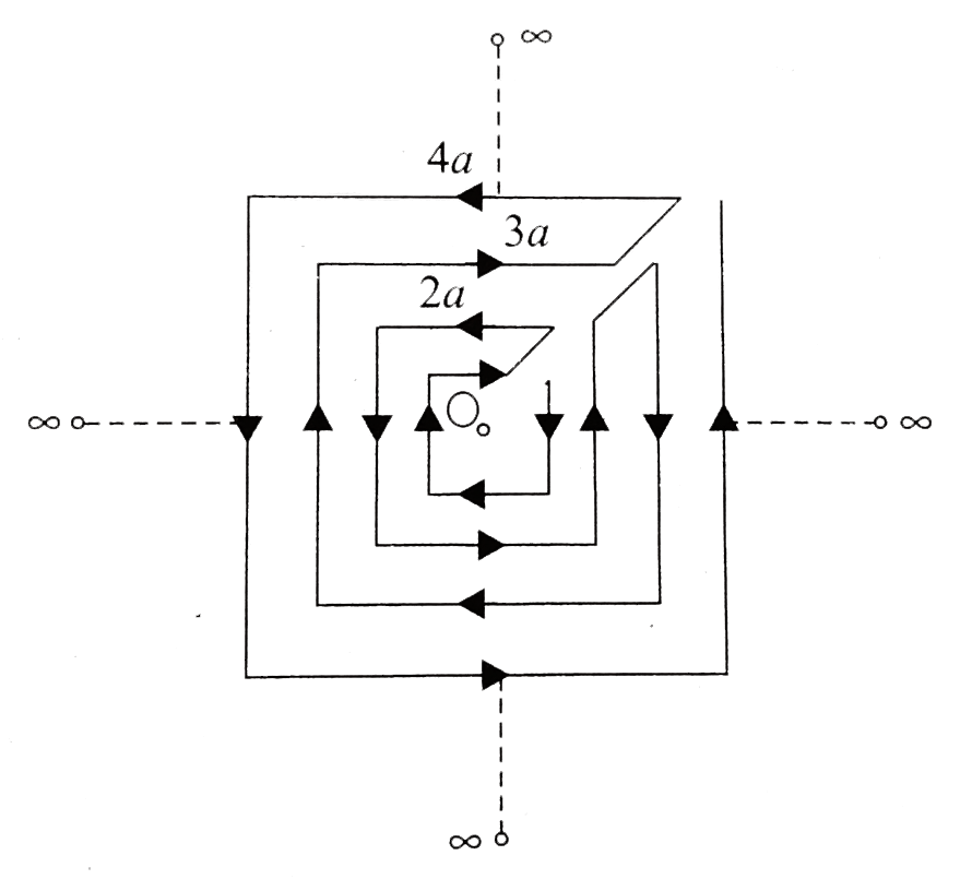
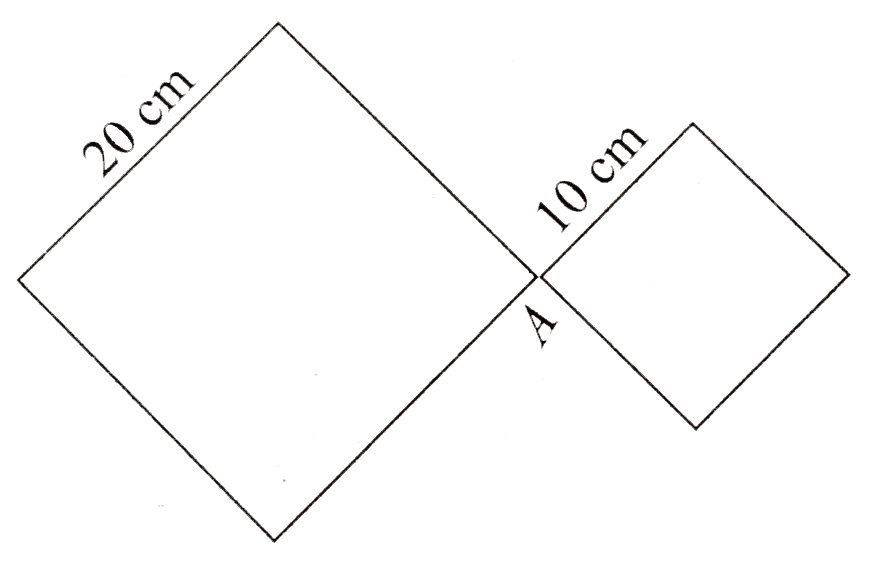
View SolutionDetermine the magnetic field at the centre of the current carrying wire arrangement shown in Fig. The arrangement extends to infinity. (The wires joining the successive squares are along the line passing through the centre).
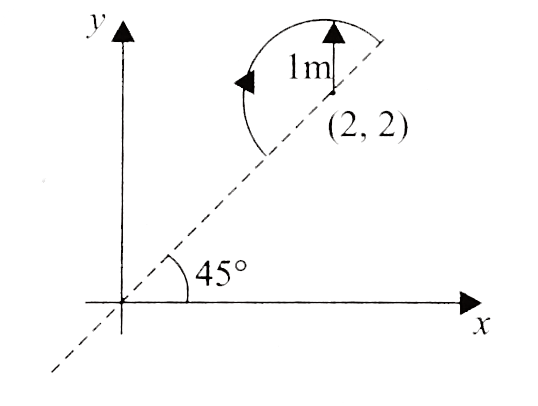
View SolutionA uniform magnetic field `vec(B) = 3 hat i + 4 hat j + hat k` exists in region of space. A semicircular wire of radius of 1 m carrying current 1 A having its centre at (2, 2, 0) is placed in x-y plane as shown in Fig. The force on semicircular wire will be
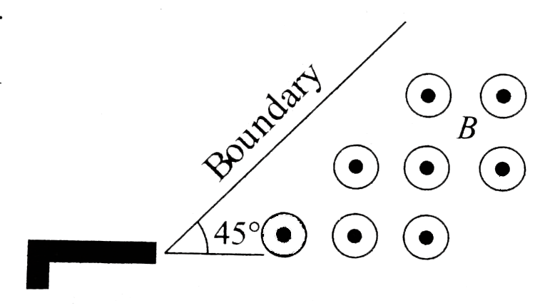
View SolutionAn electron gun ejects electrons at an angle of `45^(@)` with magnetic field boundary as shown in Fig. Find the angular deviation of electrons as it comes out of field.
View SolutionIn a certain region of space, there exists a uniform and constant electric field of strength E along x-axis and uniform constant magnetic field of induction B along z-axis. A charge particle having charge q and mass m is projected with speed v parallel to x-axis from a point (a, b, 0). When the particle reaches a point 2a, `b//2`, 0 its speed becomes 2v. Find the value of electric field strength of m, v and co-ordinates.
View SolutionA particle of specific charge `q//m = (pi) C//kg` is projected from the origin towards positive x-axis with a velocity of `10 m//s` in a uniform magnetic field `vec(B) = -2 hat K` Tesla. The velocity `vec V` of the particle after time `t =1//6` s will be
View SolutionAn `(alpha)`-particle and a proton are both simultaneously projected in opposite direction into a region of constant magnetic field perpendicular to the direction of the field. After some time it is found that the velocity of the `(alpha)`-particle has changed in a direction by `45^(@)`. Then at this time, the angle between velocity vectors of `(alpha)`-particle and proton is
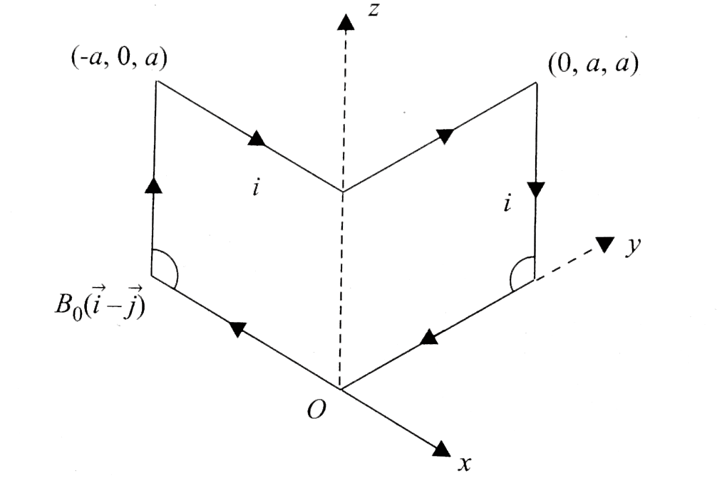
View SolutionThe torque experienced by a given current carrying loop in a uniform magnetic field `vec(B) given by B_(0)(hat i- hat j)` would have magnitude
View SolutionA wire is wound on a long rod of material of relative permeability `mu_(r) = 4000` to make a solenoid. If the current through the wire is 5 A and number of turns per unit length is 1000 per metre, then the magnetic field inside the solenoid is
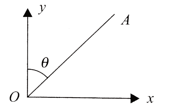
View SolutionA uniform magnetic field B and electric field E exist along y and negative z axis respectively. Under the influence of these field a charge particle moves along OA undeflected. If electric field is switched off, find the pitch of helical trajectory in which the particle will move.
View SolutionAxis of a solid cylinder of infinite length and radius R lies along y-axis. It carries a uniformly distributed current I along +y direction. Magnetic field at a point `(R//2, y, R//2)` is
View SolutionA cylinder wire of radius R is carrying uniformly distributed current I over its cross-section. If a circular loop of radius r is taken as amperian loop, then the variation value of `oint vec(B)* Vec(dl)` over this loop with radius 'r' of loop will be best represented by
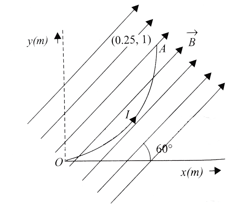
View SolutionA parabolic section of wire OA is located in the x-y plane and carries current `I=12 A`. A uniform magnetic field `B=4.0 T` making an angle `60^(@)` with x axis exists in x-y plane. Calculate the magnetic force on the wire OA. Coordinates of A are (0.25 m, 1 m)
View SolutionTwo coils of self inductance 100 mH and 400 mH are placed very closed to each other. Find maximum mutual inductance between the two when 4 A current passes through them.
View SolutionIn a region at a distance r from z-axis, magnetic field `vec(B) = B_(0)rt hat(k)` is present where `B_(0)` is constant and t is time. Then the magnetic of induced electric field at a distance r from z-axis is given by
View SolutionA small square loop of edge a and resistance R is moved with velocity `v_(0)` away from an infinitely long current carrying conductor carrying current I so that the conductor and side of square are always in same plane. Find induced current in loop at a separation of `r`
View SolutionIn Fig. two air-cored solenoid P and Q have been shown. They are placed near each other. In Fig. when `I_(p)` the current in P, changes at the rate of `5 A//s`, and emf of 2 mV is induced in Q. The current in P is then switched off, and a current changing at `2 A//s` is fed through Q as shown in diagram. What emf will be induced in P?

View SolutionRadius of a circular ring is changing with time and the coil is placed in uniform magnetic field perpendicular to its plane. The variation of 'r' with time 't' is shown in Fig. Then induced emf e with time t will be best represented by

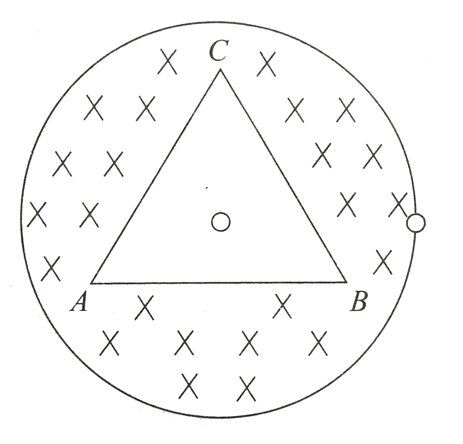
View SolutionA triangular wire frame (each side =2m) is placed in a region of time variant magnetic field `dB//dt = (sqrt3) T//s`. The magnetic field is perpendicular to the plane of the triangle and its centre coincides with the centre of triangle. The base of the triangle AB has a resistance `1(Omega)` while the other two sides have resistance `2(Omega)` each. The magnitude of potential difference between the points A and B will be
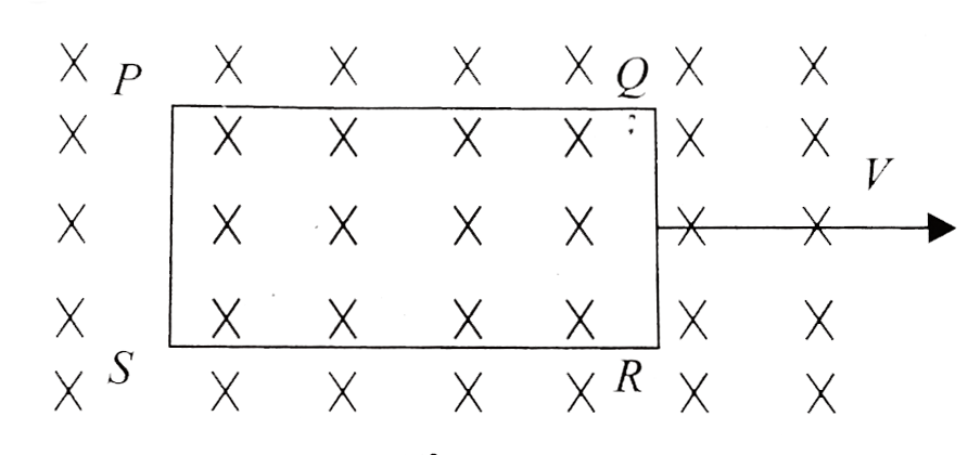
View SolutionA metallic square loop PQRS is moving in its own plane with velocity v in a uniform magnetic field perpendicular to its plane as shown in Fig. If `V_(P), V_(Q), V_(R) and V_(S)` are the potentials of points P, Q, R and S then which of the following is an incorrect statement?
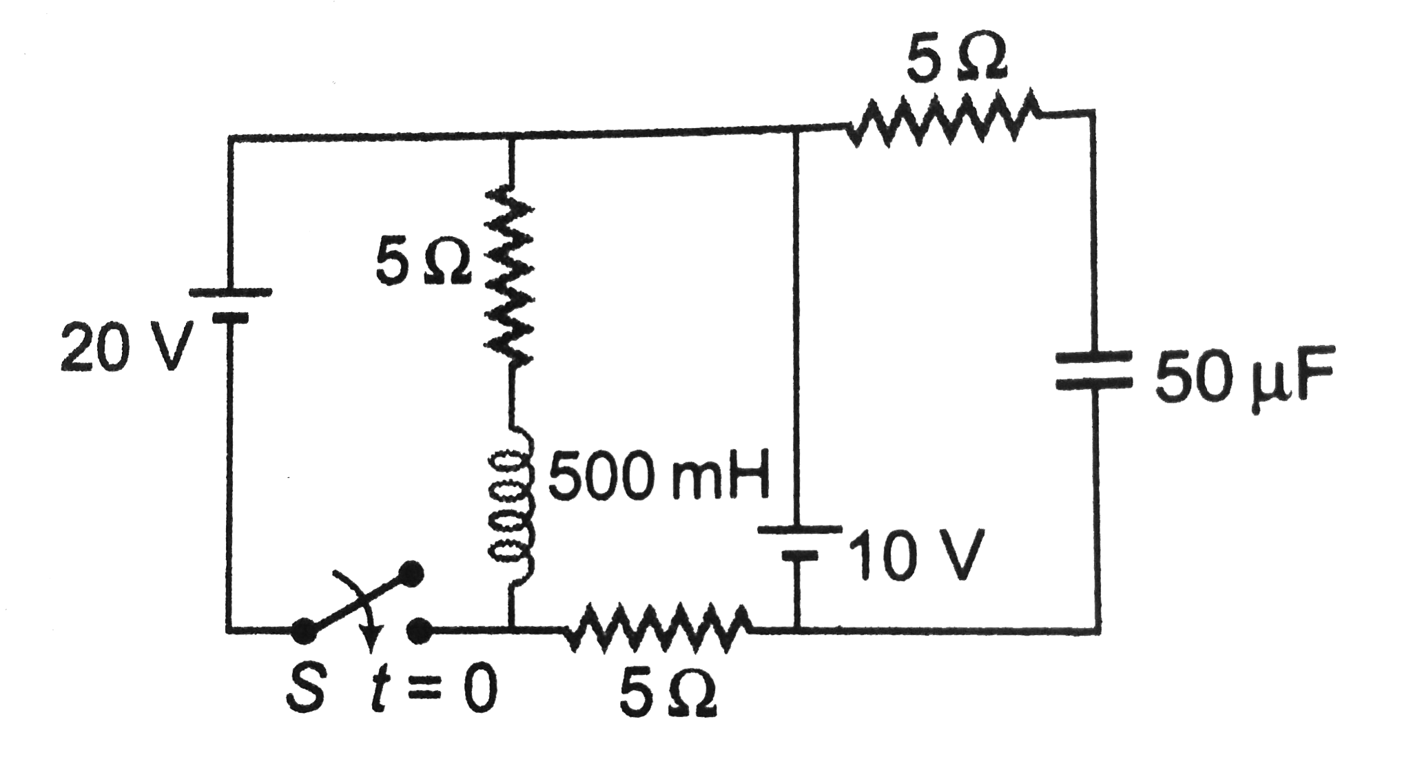
View SolutionSwitch `S` is closed `t=0`, in the circuit shown. The change in flux in the inductor `(L=500mH)` from `t=0` to an instant when it reaches steady state is
View SolutionAn `AC` source rated `100 V (rms)` supplies a current of `10 A(rms)` to a circuit. The average power delivered by the source
View SolutionThe voltage of an AC source varies with time according to the relation: ` E = 120 sin 100 pi t cos 100 pi t V`. What is the peak voltage of the source?
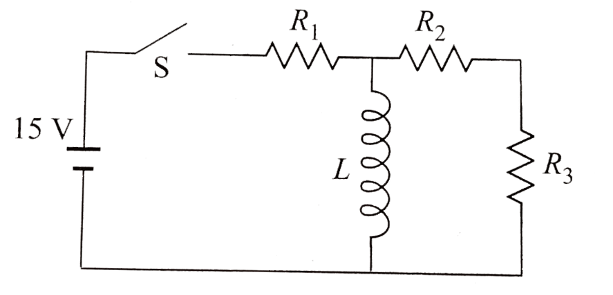
View SolutionThe figure below shown a battery with emf 15 V in a circuit with `R_(1) = 30 (Omega), R_(3) = 20 (Omega and L = 3.0 H`. The switch S is initially in the open position and is then closed at time t = 0. Then the graph which shows the correct variation of current through battery after switch S is closed
View SolutionA plane loop is shaped as two squares (Fig) and placed in a uniform magnetic field at right angle to the loop's plane. The magnetic induction varies with time as `B =B_(0) sin (omega)t, where B_(0) = 10 mT and (omega) = 100 rads^(-1)`. The wires do not touch at point A. If resistance per unit length of the loop is `50 m(Omega)// m`, then amplitude of current induced in the loop is
View SolutionTwo infinitely long, thin, insulated, straight wires lie in the x-y plane along the x- and y- axis respectively. Each wire carries a current I, respectively in the positive x-direction and positive y-direction. The magnetic field will be zero at all points on the straight line:
View SolutionTwo infinitely long straight parallel wires carry equal currents 'I' in the same direction and are 2 m apart. Magnetic induction at a point which is at same normal distance `(sqrt2) m` from each wire has magnitude
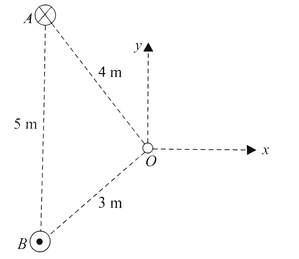
View SolutionTwo infinitely long straight parallel wire are 5 m apart, perpendicular to the plane of paper. One of the wires, as it passes perpendicular to the plane of paper, intersects it at A and carries current I in the downward direction. The other wire intersects the plane of paper at point B and carries current k int the outward direction O in the plane of paper as shown in Fig. With x and y axis shown, magnetic induction at O in the component form can be expressed as
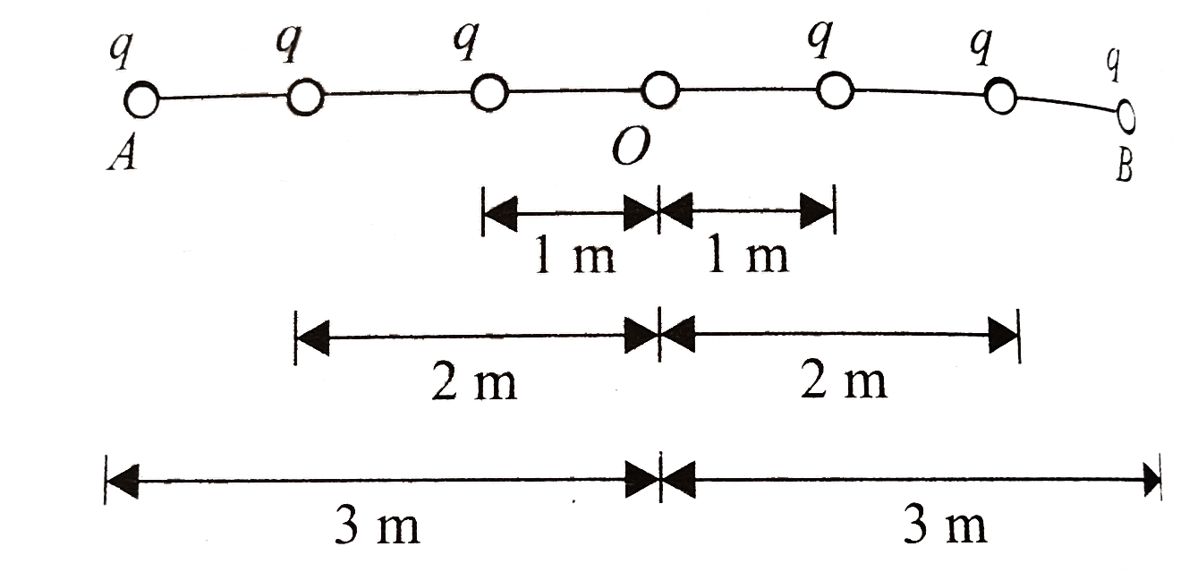
View SolutionIn Fig. , AB is a non-conducting rod. Equal charges of magnitude q are fixed at various points on the rod as shown. The rod is rotated uniformly about an axis passing through O and perpendicular to its length such that linear speed at the end A or B of the rod is `3 ms^(-1)`. Magnetic field at O is
View SolutionInfinite wires, each carrying a current 0.5 A, are kept parallel to y-axis and intersecting x-axis at `x=+-1` m, `+02 m`, `+-4 m`, `+-8m` etc. Wires kept at positive values of x carry current in the same direction while wires kept at negative values of x carry current successively in opposite directions as shown in Fig.
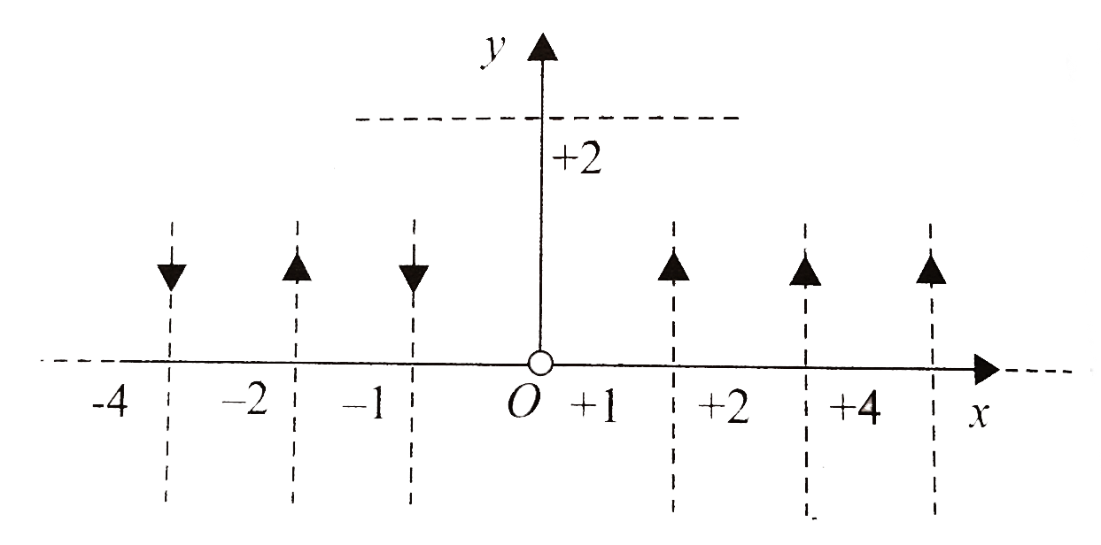
A wire is kept parallel to x-axis and intersecting y-axis at y=2 m. It carries a current i. Assuming this wire to be insulated from others then the current i in it such that magnetic induction at O is zero is
(assuming each wire to be infinitely long)
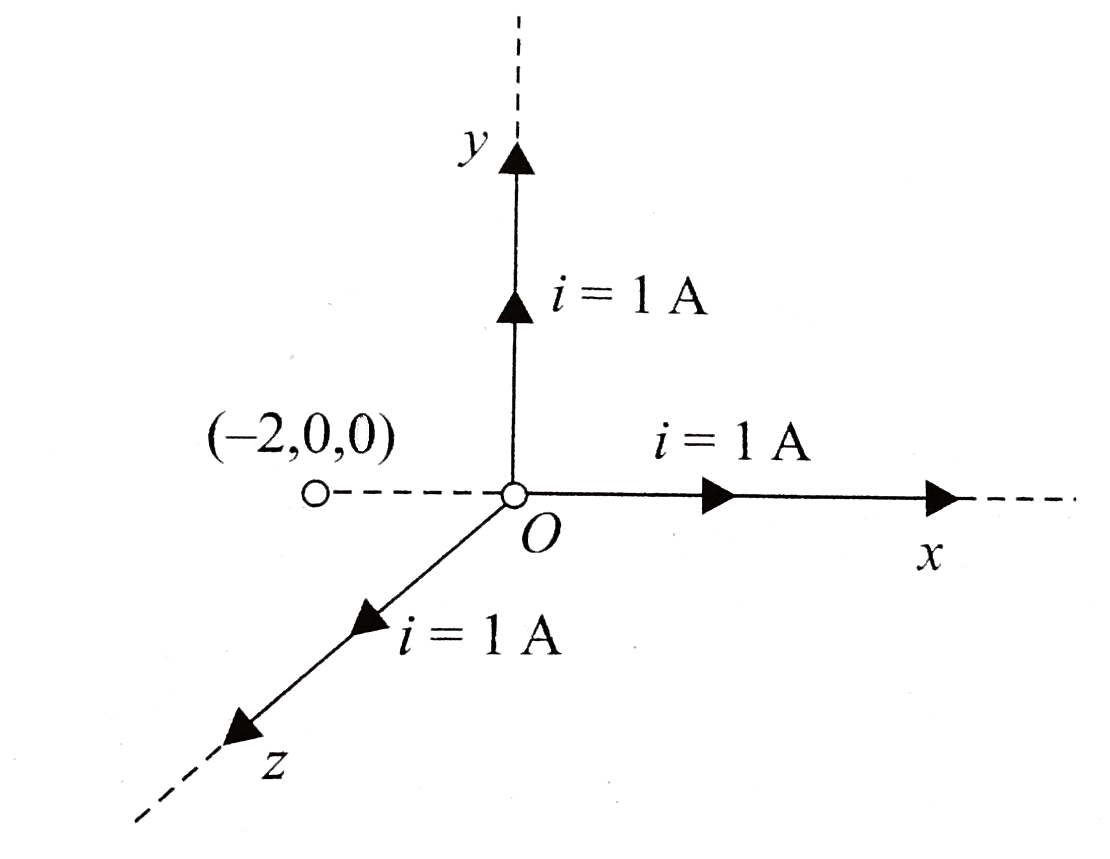
View SolutionThree infinitely long wires, each carrying a current 1A, are placed such that one end of each wire is at the origin, and, one of these wires is along x-axis, the other along y-axis and the third along z-axis. Magnetic induction at point (-2 m, 0, 0) due to the system of these wires can be expressed as
View SolutionTwo parallel wires P and Q placed at a separation d =6 cm on x-axis carry electric current `i_(1) = 5A and i_(2) = 2 A` in opposite directions as shown in Fig. Find the point on the line PQ where the resultant mgnetic field is zero.

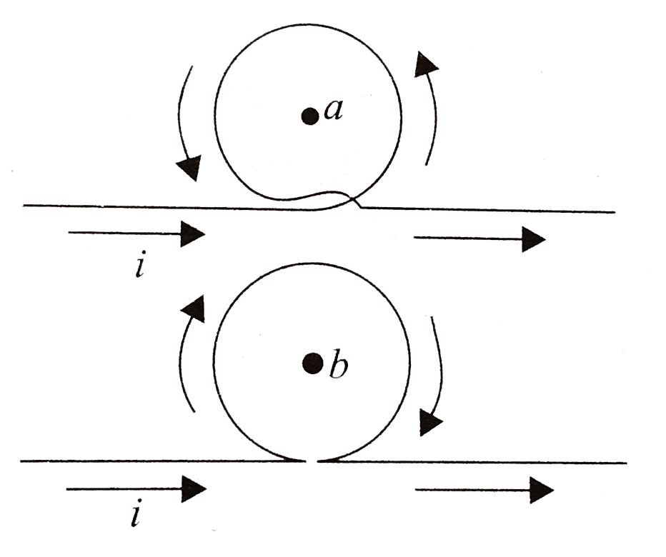
View SolutionIn Fig. the conductors carry equal currents i. All straight segments are very long, and the two circular loops have equal radii. However, the currents around the loops have opposite sense. The ratio of the magnetic field at a and b, at the centres of the two loops, is
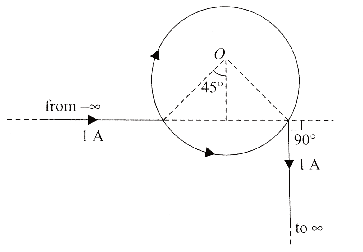
View SolutionWhat is the magnitude of magnetic field at the centre O of loop of radius `(sqrt2) m` made of uniform wire when a current of 1 A enters in the loop and is taken out of it by two long wires as shown in Fig.
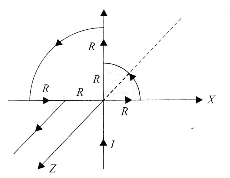
View SolutionFind the magnetic field at the origin in the fig. Shown in fig.
View SolutionFind the magnitude of the magnetic induction B of a magnetic field generated by a system of thin conductors along which a current I is flowing at a point A (O, R, O), that is the centre of a circular conductor of radius R. The ring is in yz plane.
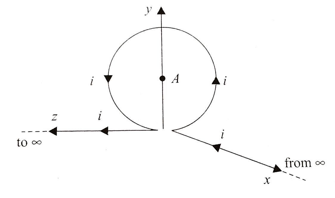
View SolutionA charged particle (charge q, mass m) has velocity `v_(0)` at origin in +x direction. In space there is a uniform magnetic field B in -z direction. Find the y coordinate of particle when is crosses y axis.
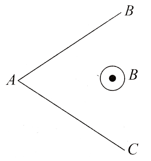
View SolutionAB and AC are boundary lines within which a magnetic field B exists. If the magnetic field is absent, a charged particle of mass m and charge q must have passed through a point P on angle bisector of -BAC, at a distance `r(sqrt2)` from A, if it has fallen on AB normally at a point Q such that QP =r. If the magnetic field is present, how much time the charged particle will take to come out of the magnetic field
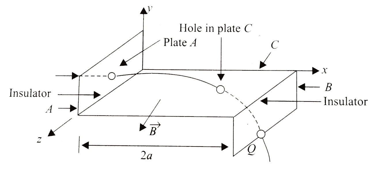
View SolutionTwo recangular plates A and B placed at a distance 2a apart, are connected to a battery to produce an electric field. There are insulators between plantes C and other two plates. A magnetic field exists along z-axis. A charged particle of mass m and charge q passes through a hole at the middle of the plate A with velocity v and strikes at Q which is the middle of the bottom edge of plate B after passing through a hole inplate C. If `E = mv^(2)//qa`, what will be the speed of the particle at Q?
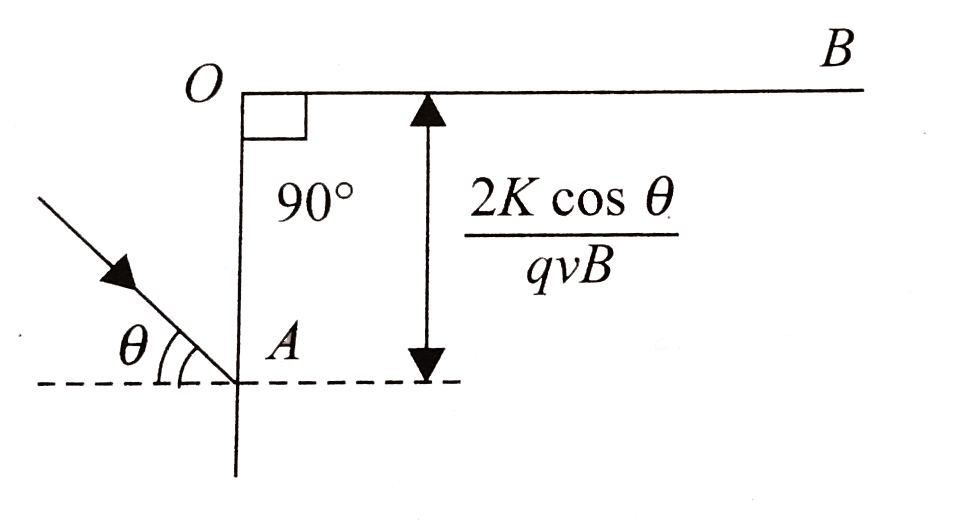
View SolutionA magnetic field B exists between OA and OB. Inclined at an angle `(theta)`, a charged particle strikes at point A on surface OA, at a distance `(2K cos(theta))(qvB)` from O, where K is kinetic energy, q is the charge and v is the velocity of the particle. At what angle with horizontal (measured from end B) will the charged particle emerge from OB?
View SolutionTo the right of line PQ is a uniform magnetic field `vec(B).B_(1)A` is the line of incidence of a charged particle, which comes out of the field along DE, CA and DF are the normals at A and D. `-B_(1)AC =(theta)`. Angle measured from CA in clockwise direction is taken as positive. What will be the value of `(theta)` so that angle subtended by the part of the circle (along which charged particle moves in the field) at its centre and facing the circle is less than `pi`?
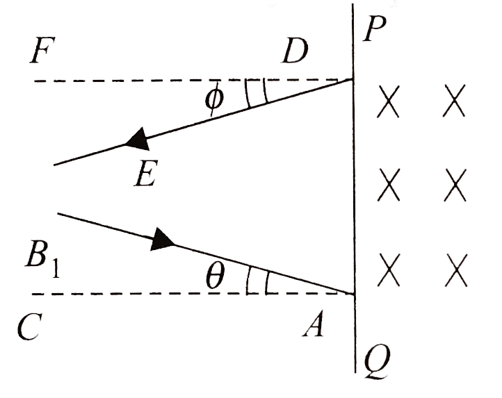
View SolutionIn the previous problem, if O is the point on AD and `OO_(1)` is the perpendicular from the centre of the circle, `O_(-1), then OA//OD` will be
View SolutionIn the previous problem, if `(phi)` is the angle between line of emergence DE and normal DF at point D, ratio of `(phi)//(theta)` for positive value of `(theta)` will be
View SolutionIn the previous problem, if time period, `T =2(pi) m/(BQ)` where Q is the charge of the particle and m is its mass, the ratio of time spent by the particle in field when `(theta)` is positive to when `(theta)` is negative is given by
View SolutionIn the previous problem, the maximum range of movement of the centre of the part of the circle from line AD in which charged particle of charge Q moves with a velocity v when `(theta)` is positive to when `(theta)` is negative is given by
View SolutionA triangular system of mass 100 gm consisting of 3 wires of length, as shown in Fig and length of AO as 4 units, are placed in the magnetic field of 1T. The current of 1 A flows through wire AO. The wires are of same material and cross-sectional area. In which direction will the system move?
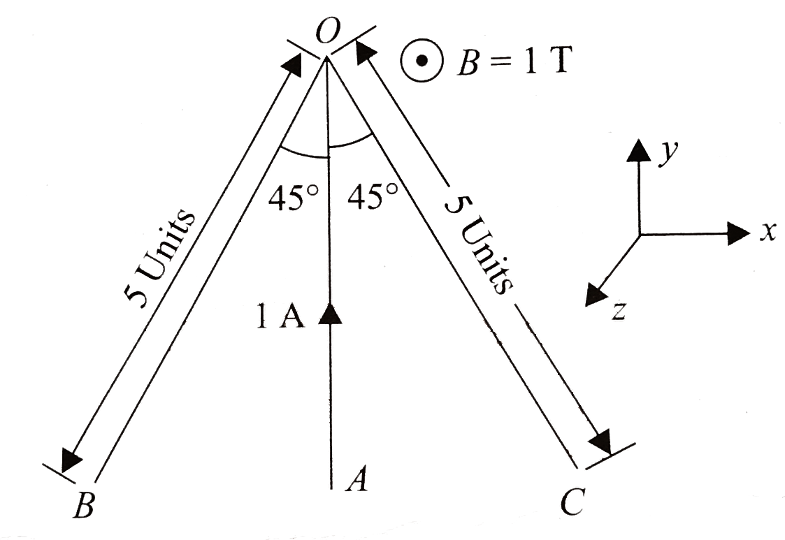
View SolutionIn the previous problem, what will be force with which system moves? `(Use (sqrt2) =1.4)`
View SolutionIn the previous problem, instead of being stationary, the system enters the magnetic field with a velocity `0.5 m// sec` along y-direction. Along which direction the system will move now?
View SolutionIn the previous problem, what will be acceleration of the system (in` m//sec^(2))`?
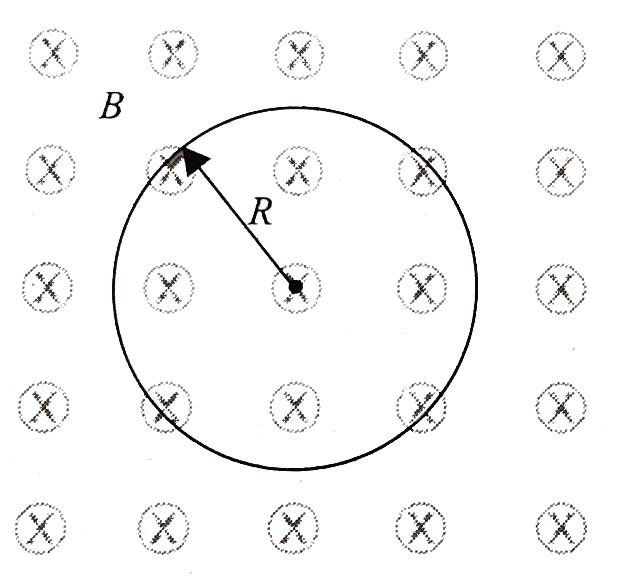
View SolutionA conducting loop of radius R is present in a uniform magnetic field B perpendicular to the plane of the ring. If radius R varies as a function of time t, as `R =R_(0) +t`. The emf induced in the loop is
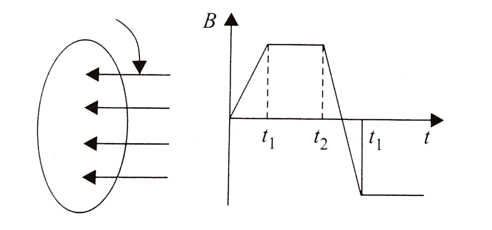
View SolutionA wire loop is placed in a region of time varying magnetic field which is oriented orthogonally to the plane of the loop as shown in Fig. The graph shows the magnetic field variation as the function of time. Assume the positive emf is the one which drives a current in the clockwise direction and seen by the observer in the direction of B. Which of the following graphs best represents the induced emf as a function of time?
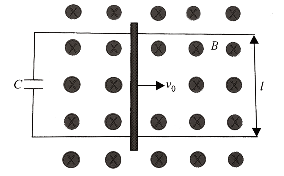
View SolutionTwo infinitely long conducting parallel rails are connected through a capacitor C as shown in Fig. A conductor of length l is moved with constant speed `v_(0)`. Which of the following graph truly depicts the variation of current through the conductor with time?
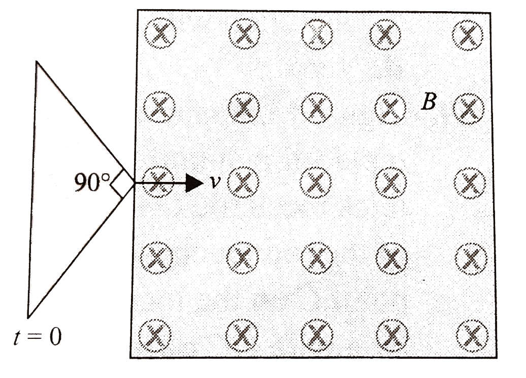
View SolutionFigure shows an isosceles triangle wire frame with apex angle equal to `(pi)//2`. The frame starts entering into the region of uniform magnetic field B with constant velocity v at t =0. The longest side of the frame is perpendicular to the direction of velocity. If i is the intantaneous current through the frame then choose the alternative showing the correct variation of i with time.
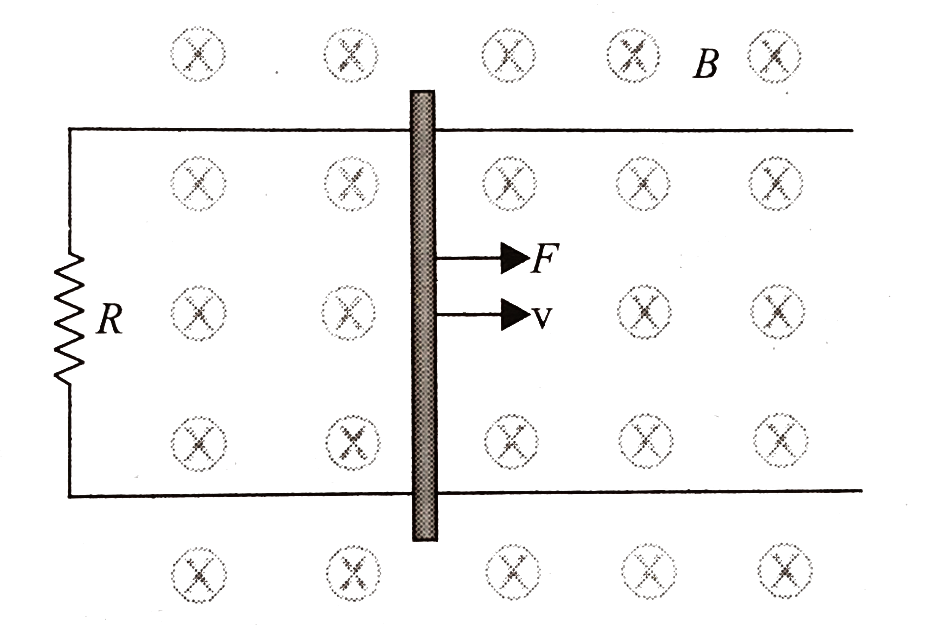
View SolutionA rod closing the circuit shown in Fig moves along a U shaped wire at a constant speed v under the action of the force F. The circuit is in a uniform magnetic field perpendicular to the plane. Calculate F if the rate of heat generation in the circuit is Q.
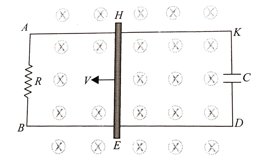
View SolutionIn the circuit shown in Fig. A conducting wire HE is moved with a constant speed v towards left. The complete circuit is placed in a uniform magnetic field `vec(B)` perpendicular to the plane of circuit inwards. The current in HKDE is
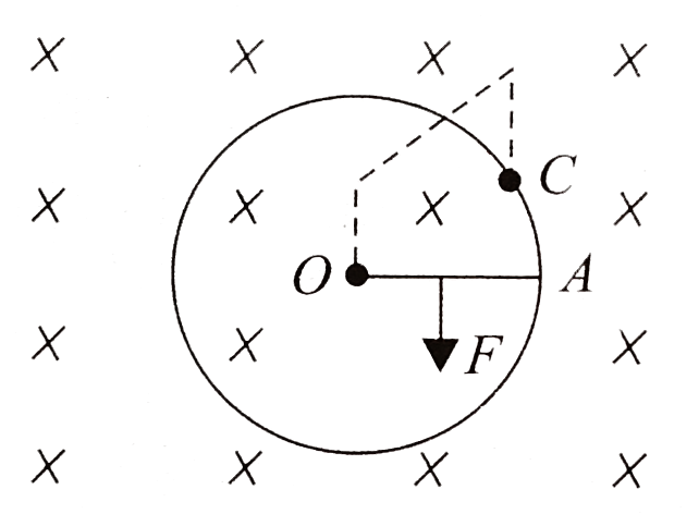
View SolutionFig. Shows a conducting circular loop of radius a placed in a uniform, perpendicular magnetic field B. A thick metal rod OA is pivoted at the centre O. The other end of the rod touches the loop at A. The centre O and a fixed point C on the loop are connected by a wire OC of resistance R. A force is applied at the middle point of the rod OA perpendicularly, so that the rod rotates clockwise at a uniform angular velocity `(omega)`. Find the force.
View SolutionConsider the situation shown in the figure of the previous problem. Suppose the wire connecting O and C has zero resistance but the circular loop has a resistance R uniformly distributed along its length. The rod OA is made to rotate with a uniform angular speed `(omega)` as shown in the figure. Find the current in the rod when `-AOC = 90^(@)`
View SolutionConsider a variation of the previous problem. Suppose the circular loop lies in a vertical plane. The rod has a mass m. The rod and the loop have negligible resistance but the wire connecting O and C has a resistance R. The rod is made to rotate with a uniform angular velocity `(omega)` in the clockwise direction by applying a force at the midpoint of OA in a direction perpendicular to it.
Find the magnitude of this force when the rod makes an angle `(theta)` with the vertical.
View SolutionFigure shows a situation similar to the previous problem. All parameters are the same except that a battery of emf `epsilon` and a variable resistance R are connected between O and C. The connecting wires have zero resistance. No external force is applied on the rod (except gravity, forces by the magnetic field and by the pivot).
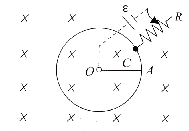
In what way should the resistance R be changed so that the rod may rotate with uniform angular velocity in the clockwise direction? Express your answer in terms of the given quantities and the angle `(theta)` made by the rod OA with the horizontal.
View SolutionIn the circuit shown in Fig. Sliding contact is moving with uniform velocity towards right. Its value at some instance is `12 (Omega)`. The current in the circuit at this instant of time will be

View SolutionThe current i in an induction coil varies with time according to the graph shown in figure. Which of the following graph shows induced emf in the coil with time:
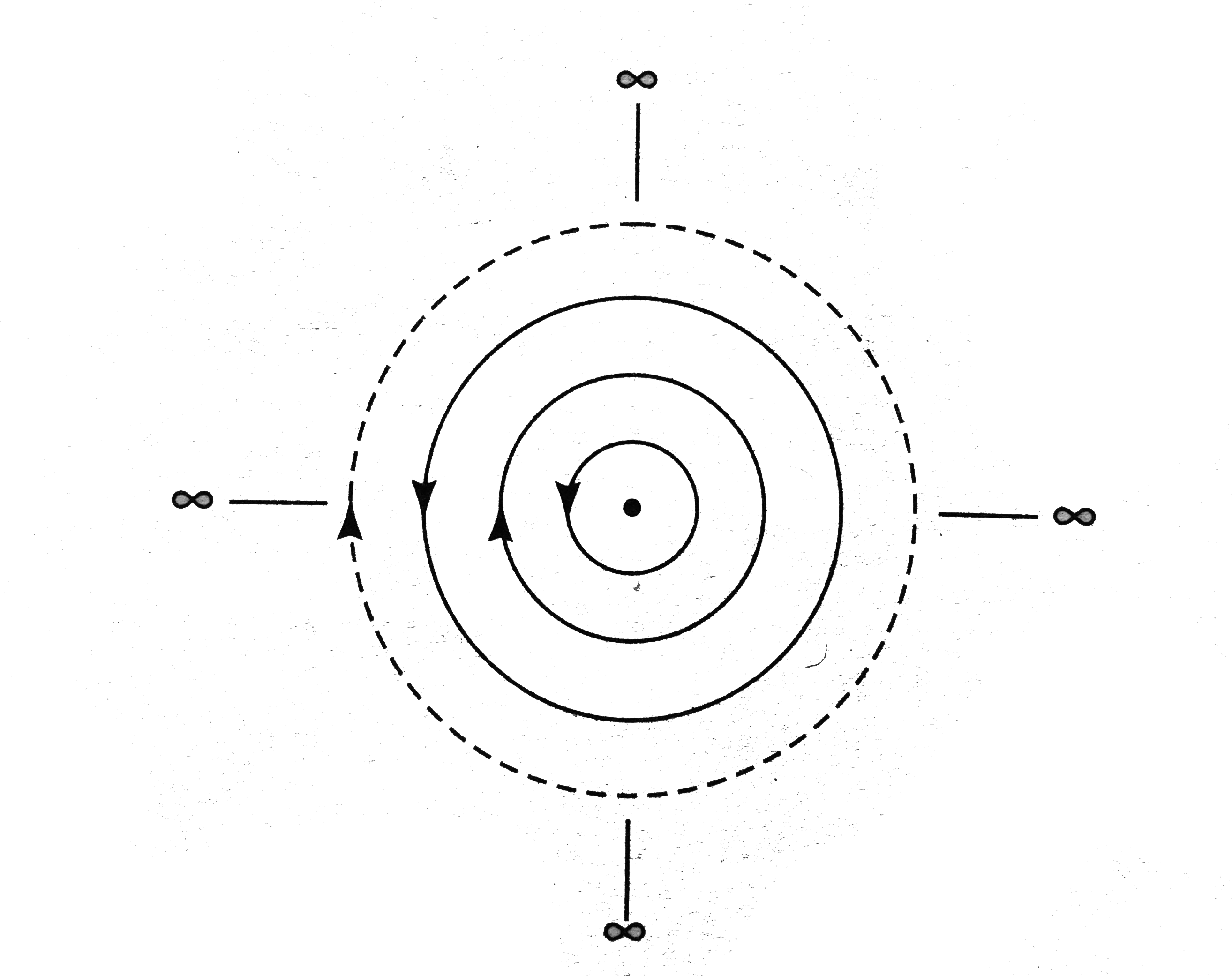
View SolutionIn Fig. infinite conducting rings each having current i in the direciton shown are placed concentrically in the same plane as shown in the figure. The radii of rings are `r,2r,2^2r,2^3r,......,(oo)`. The magnetic field at the centre of rings will be
View SolutionThe magnetic field exists along negative x-axis and electric field exists along positive x-axis. A charged particle moves with a velocity inclined at an angle `(theta)` with vertical in (x-y) plane. What will be the correct diagram of the helical path?
View SolutionOne long conductor carries current I along y-axis with charge density `lambda`. An electric field exists along z-axis. In what direction, a charged particle at point P, distance x apart from the wire (along x-axis), be projected with velocity v so that it moves undeflected?

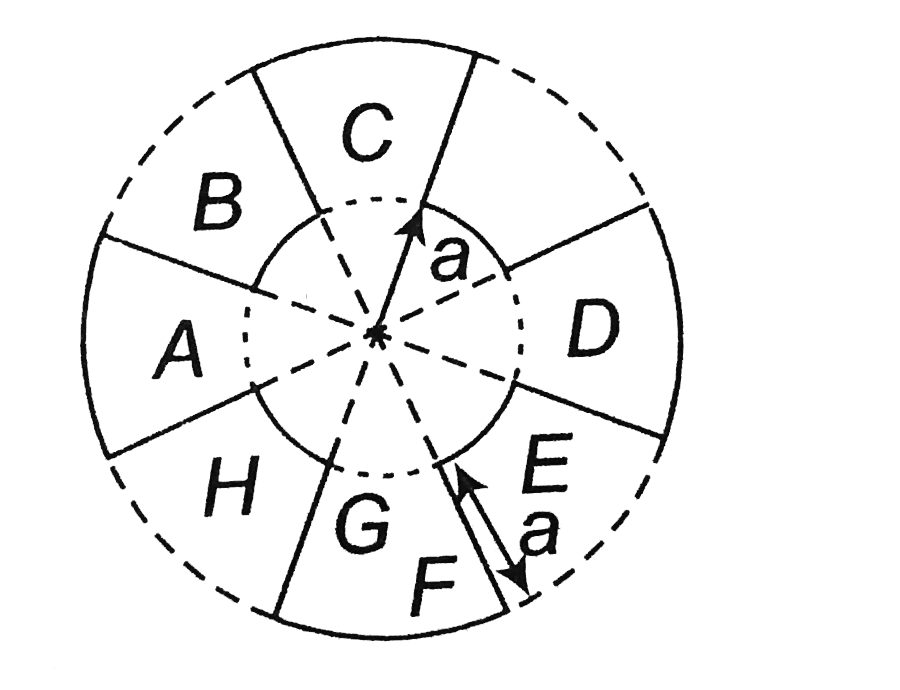
View SolutionCurrent `I` flows through the circuit, as shown. Find the magnetic moment of the figure, if `AB=BC=CD=DE=EF=FG=GH=HA`:
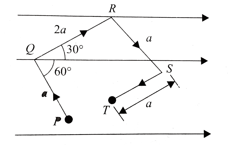
View SolutionFind the force acting on rectangular loop PQRST.
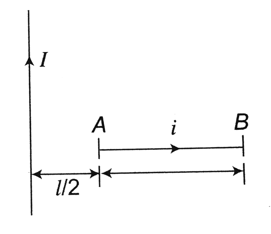
View SolutionA conductor `AB` of length `l` carrying current `i` is placed perpendicular to a long straight conductor carrying a current `I` as shown. Force on `AB` will be
View SolutionA long straight non-conducting string carriers a charge density of `40 muC//m`. It is pulled along its length at a speed of `300 m//sec`. What is the magnetic field at a normal distance of `5 mm` from the moving string?
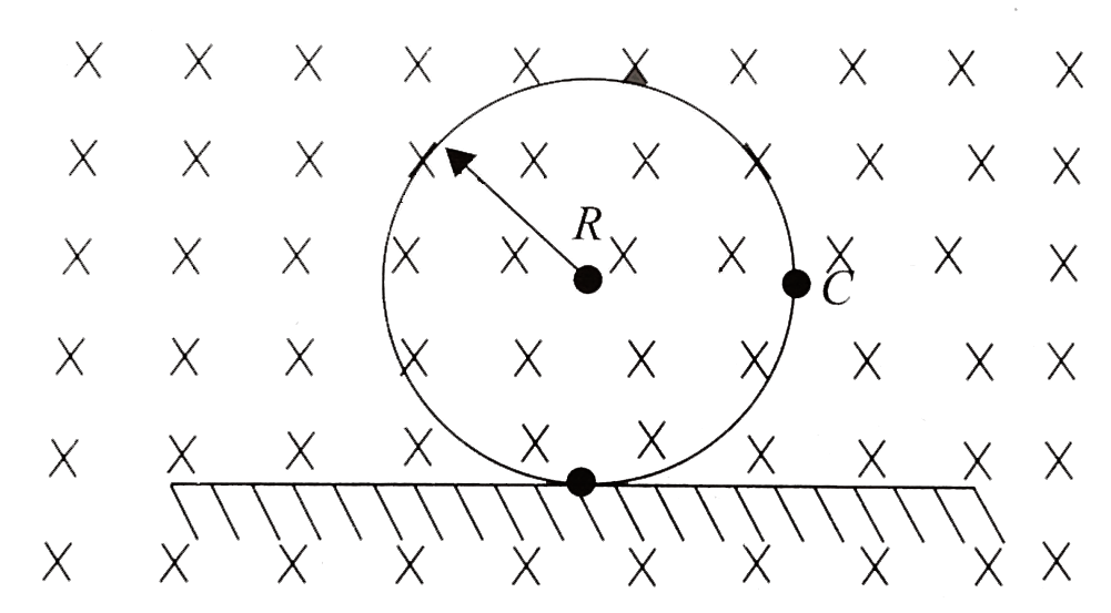
View SolutionA ring of radius R is rolling on a horizontal plane with constant velocity v. There is a constant and uniform magnetic field B which is perpendicular to the plane of the ring. Emf across the lowest point A and right-most point C as shown in the figure will
View SolutionA current `I = 3.36(1 +2t) xx 10^(-2)` A increase at a steady state in a long staight wire. A small circular loop of radius `10^(-3)` m has its plane parallel to the wire and is placed at a distance of 1 m from the wire. The resistance of loop is `8.4 xx 10^(-4) (Omega)`. Find the approximate value of induced current in the loop.
View SolutionThe magnetic field inn a region is given by `vec B = veck (B_0)/(L) y` where L is a fixed length. A conducting rod of length L lies along the Y - axis between the origin and the point (0,L, 0). If the rod moves with a velocity `v= v_0` , find the emf induced between the ends of the rod.
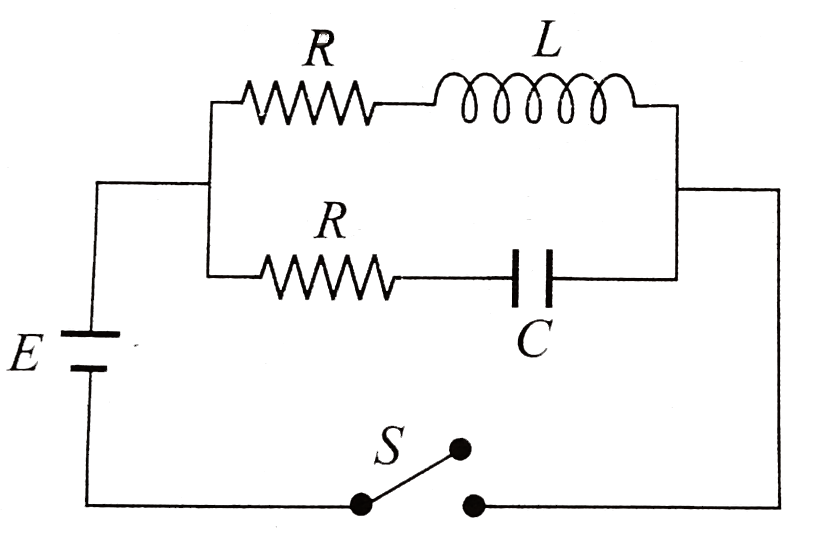
View SolutionIn the circuit shown in fig, switch S was closed for long time. At time t-0, teh switch is opened again. The maximum potential difference across teh plates of the capacitor after the switch is opened is

View SolutionIn the circuit shown in fig, the time constant of the two braches are equal(=T). Then if the key S is closed at the instant t=0, the time in which the current in the circuit through the battery will rise to its final value of `(E//R)` will be, (assume that the internal resistance of the battery and of the connecting wire are negligible)
View SolutionIn fig., a parivle of charge +Q and mass M is projected with velocity v in the plane of paper. Above teh dark line magnetic field is `(B_1)` and below it is `(B_2)` both perpendicular to the plane of paper. Which can be the possible path on which the charge will move? (Consider all posible cases for values of `(B_1)and `(B_2)`)
View SolutionA bulb of 100 W is connected in parallel to an ideal inductance of 1H. This arrangement is connected to a 90 V barrery through a switch. On pressing the switch the
View SolutionA resistance of `20 Omega` is connected to a source of an alternating potential `V=220 sin (100 pi t)`. The time taken by the current to change from the peak value to rms value is
View SolutionA uniformly wound solenoid coil of slf inductnace 4 mH and resistance `12 Omega` is broken int two parts. These two coil are connected in parallel across is `12V` battery. The steady current through battery is
View SolutionA current is made up of two components 3 A de component and ac component given by `I = 4 sin (omega)t A`. The effective value of current is
View SolutionAn alternating e.m.f. of 200 V and 50 cycles is connected to a circuit of resistance `3.142 Omega)` and inductance 0.01 H. The lag in time between the e.m.f. and the current is
View SolutionIn an AC circuit, a resistance of `Rohm` is connected is series with an inductance `L`. If phase angle between volage and current be `45^(@)`, the value of inductive reactance will be
View SolutionA direct current of 2 A and an alternating current having a maximum value of 2 A flow through two identical resistances. The ratio of heat produced in the two resistances will be
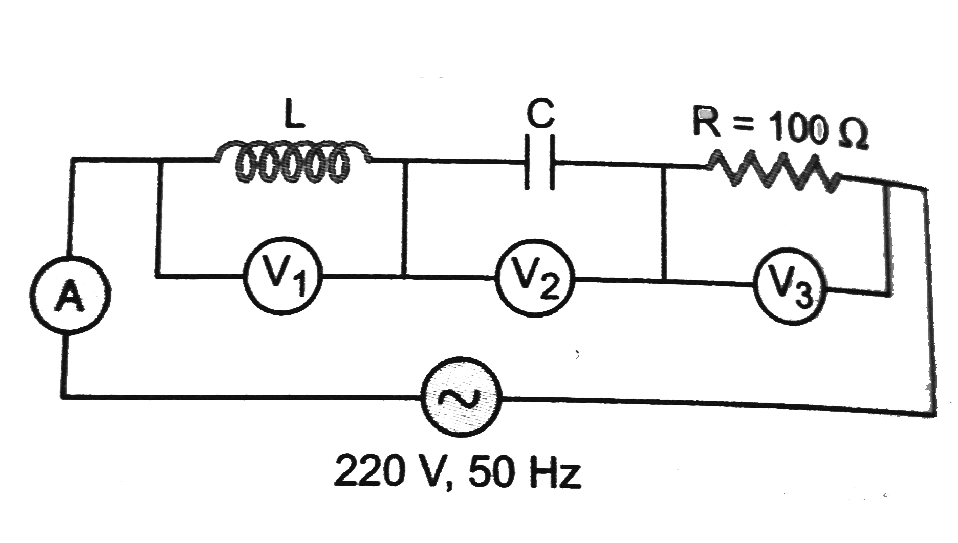
View SolutionIn the given circuit, Fig., the reading of voltmeter `V_(1)` and `V_(2)` 300 votls each. The reading of the voltemeter `V_(3)` and ammeter `A` are respectively
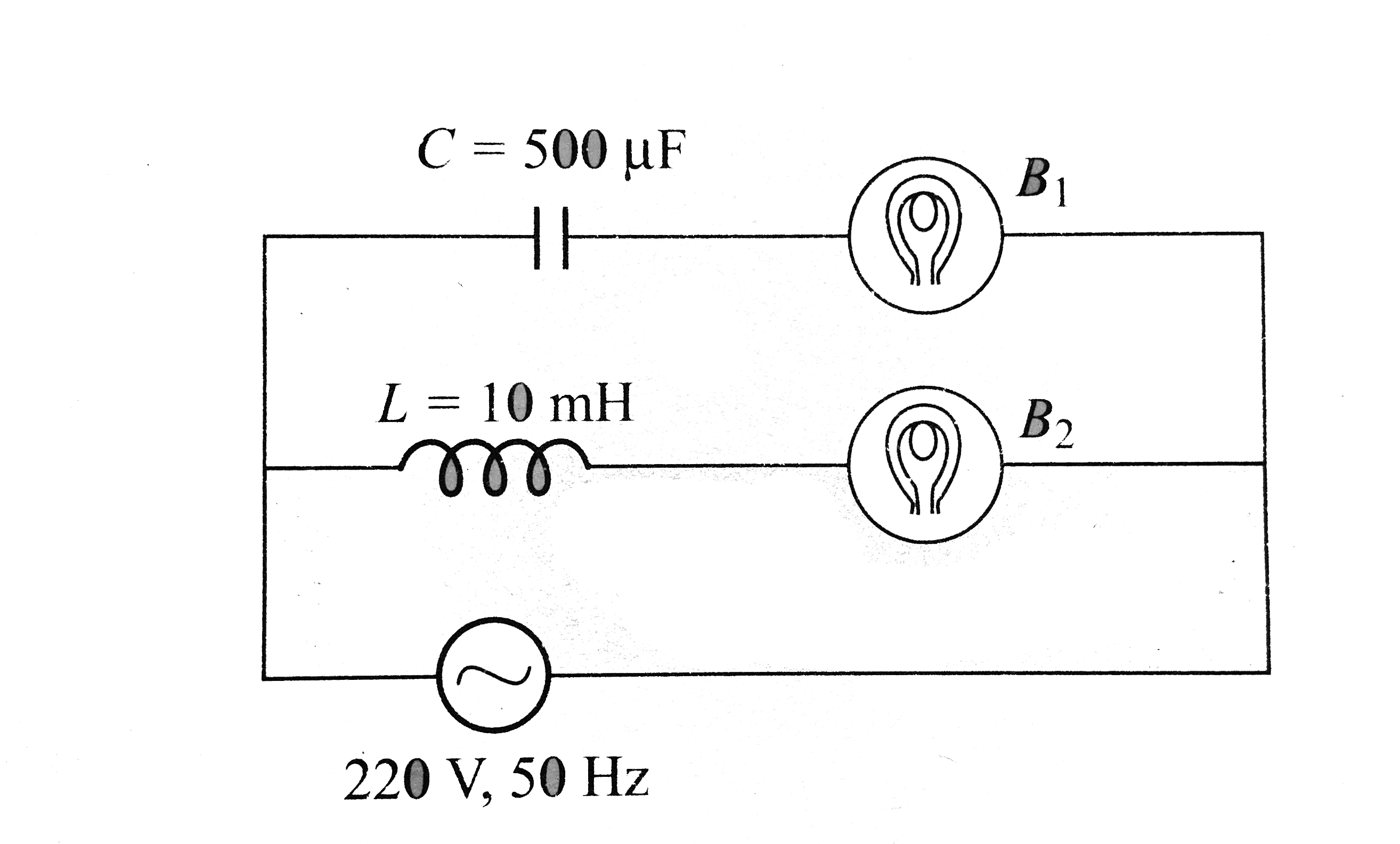
View SolutionIn the circuit shown in fig. if both the bulbs `(B_1) and (B_2)` are identical
View SolutionThe diagram given below shows a solenoid carrying time varying current `l= l_(0)t`. On the axis of the solenoid, a ring has been placed. The mutual inductance of the ring and the solenoid is M and the self inductance of the ring is L. If the resistance of the ring is R then maximum current which can flow through the ring is

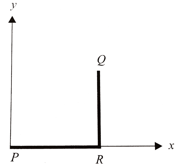
View SolutionAn inverted L shaped conductor PRQ is made by joining two perpendicular conducting rods, each of length 1.5 L, at end R. This structure is moving in x-y plane containing variable magnetic field `vec(B) = -3xhate(k)` with a velocity `vhate(i) + vhat(j)`. If potential of P is `V_(p)` and that of Q is `V_(Q)`, then value of `V_(P) - V(Q)` at the instant when P is at origin as shown in Fig. Will be
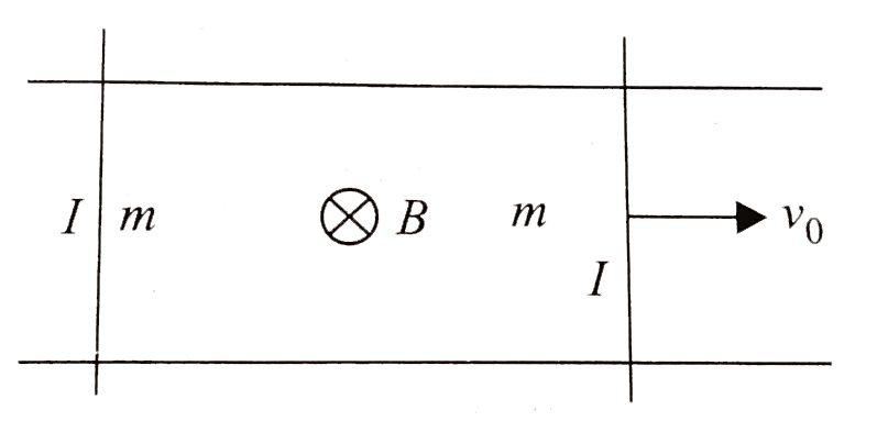
View SolutionConsider parallel conducting rails separated by a distance l. There exists a uniform magnetic field B perpendicular to the plane of the rails as shown in Fig. Two conducting wires each of length l are placed so as to slide on parallel conducting rails. One of the wires is given a velocity `v_(0)` parallel to the rails. Till steady state is achieved, loss in kinetic energy of the system is
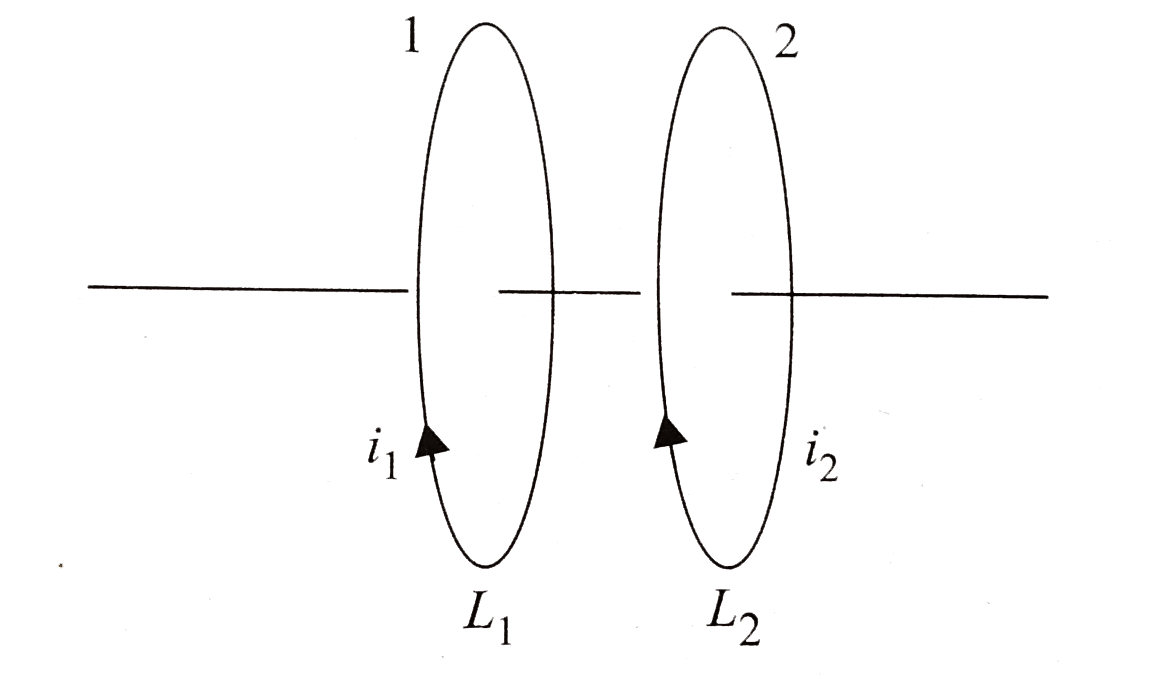
View SolutionA system consists of two coaxial current carrying circular loops as shown in Fig. The self inductance of loop 1 is `L_(1)` and self inductance of loop 2 is `L_(2)`. Magnitude of mutual inductance is M. If at any instant current flowing through loop 1 and loop 2 are `i_(1) and i_(2)` respectively, then total magnetic energy of the system is
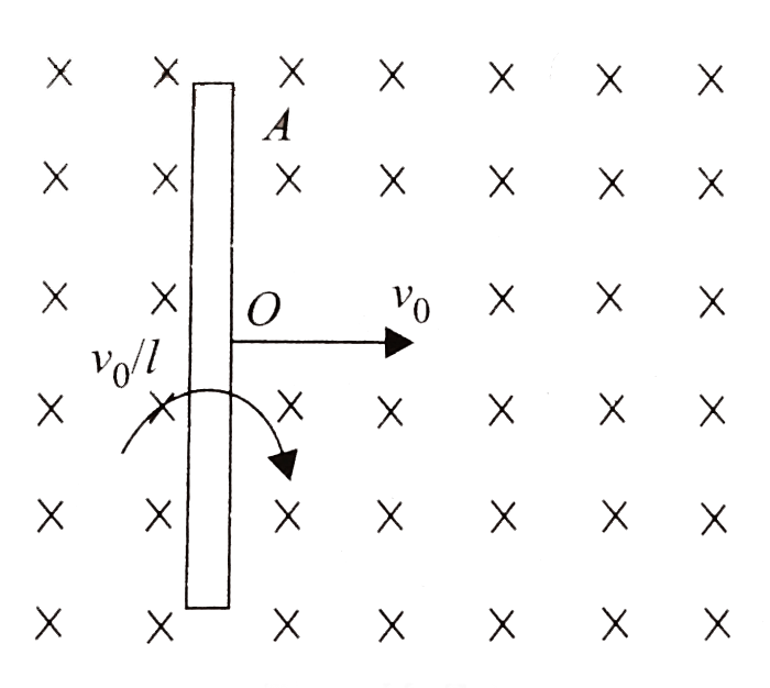
View SolutionA conducting rod of length 1 is moving on a horizontal smooth surface. Magnetic field in the region is vertically downward and magnitude `B_(0)`. If centre of mass (COM) of the rod is translating with velocity `v_(0)` and rod rotates about COM with angular velocity `v_(0)//l`, then potential difference between points O and A will be
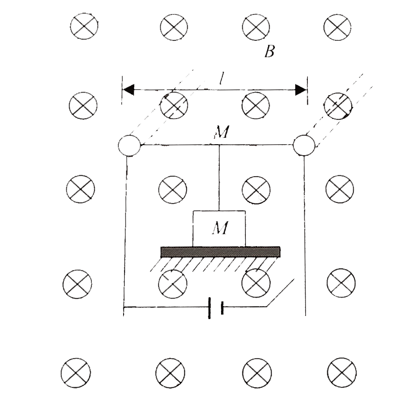
View SolutionThere exists a uniform magnetic field in horizontal direction perpendicular to the plane of the paper as shown in Fig. A wire of length 1 and mass m is attached with a block of equal mass with the help of an ideal string. The block is kept on floor and the wire on two conducting support as shown. After closing the switch, a charge q passes though the wire for a small interval of time. To what height the block will rise? `(take(qBl)/m = 20)`
View SolutionA circuit containing capacitors `C_(1) and C_(2)` shown in Fig. is in the steady state with key `K_(1)` closed. At the instant t = 0, `K_(1)` is opened and `K_(2)` is closed. The angular frequency of oscillation of the circuit and charge across `C_(1) at t = 125 (mu)s` are respectively
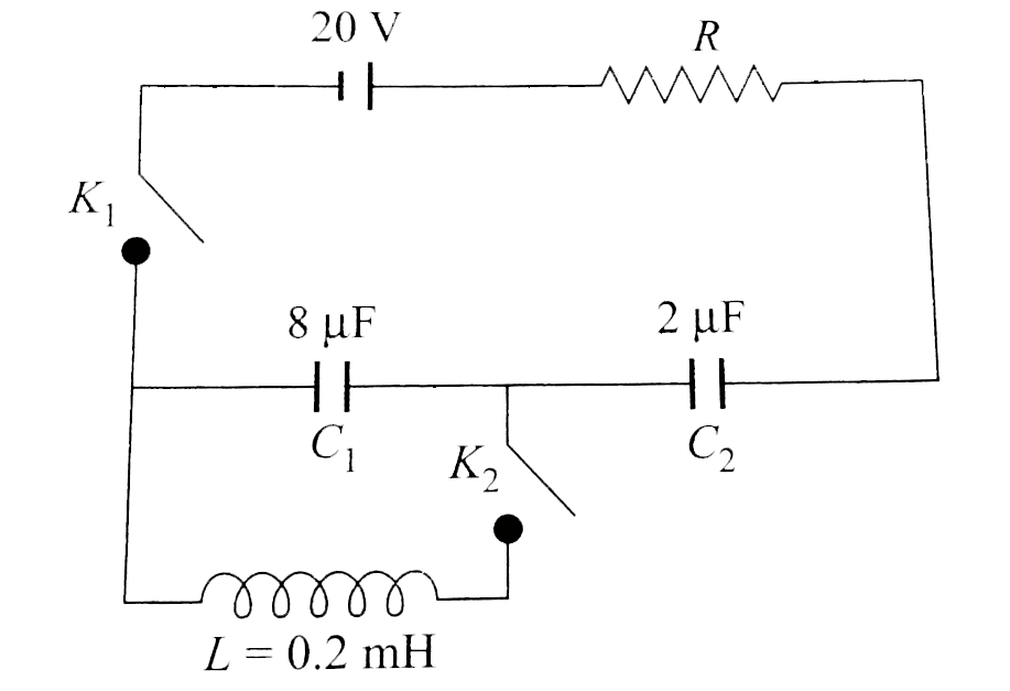
View SolutionAn inductor coil stores 32 J of magnetic field energy and dissiopates energy as heat at the rate of 320 W when a current of 4 A is passed through it. Find the time constant of the circuit when this coil is joined across on ideal battery.
View SolutionA solenoid of inductance 50 mH and resistance `10 Omega` is connected to a battery of 6V. Find the time elapsed before the current acquires half of its steady - state value.
View SolutionAn inductor-resistance -battery circuit is switched on at t = 0. If the emf of the battery in one time constant `tau`.
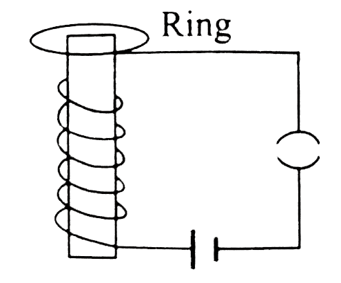
View SolutionFigure shows a powerful electromagnet arrangement. A copper ring, which is free to move, is placed on the projecting part of the core as shown.
When the key is inserted, the ring
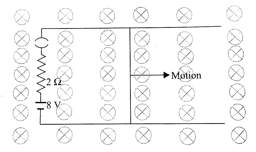
View SolutionFigure shows a conducting frame having battery and a resistance on which a movable conductor of length 0.5 m can slide, The whole arrangement is placed in a uniform magnetic field of B =0.4 T directed perpendicular and into the plane of frame. Initially the circuit is open. When the key is inserted, the conductor begins to move. It is found that a force 0.5 N has to be applied on the conductor to the left to keep it moving at constant speed to the right.
Current flowing in the conductor is:
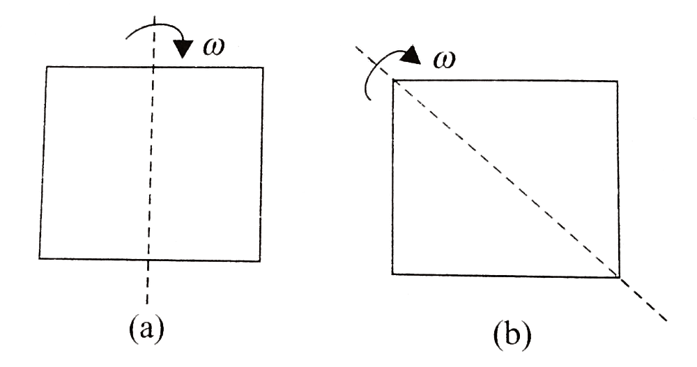
View SolutionFigures show a squre loop of side a rotating about the given axes in a uniform magnetic field such that the field is perpendicular to the axis in both cases.
Angular speed of rotation is both cases being the same,
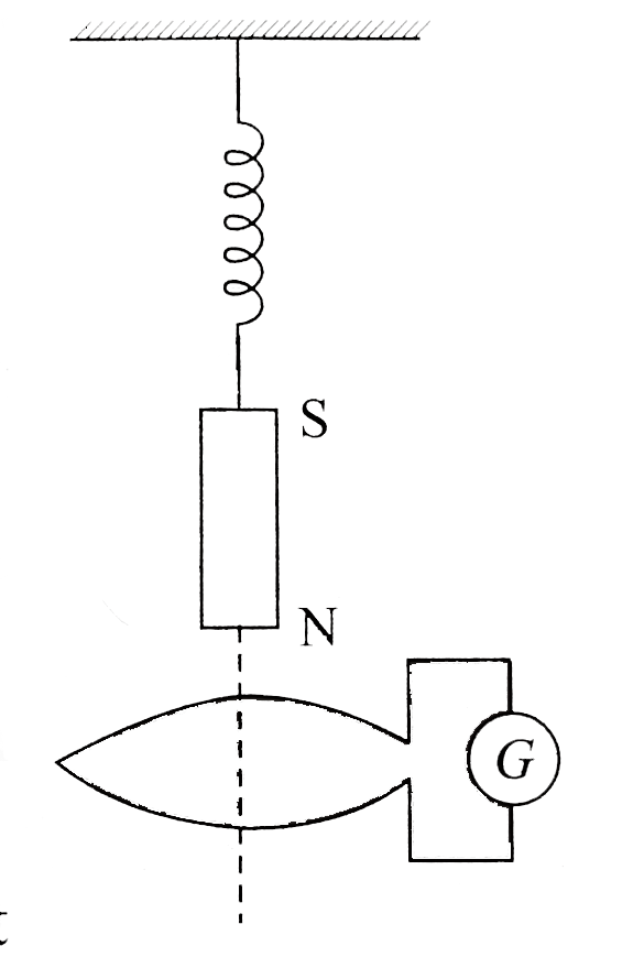
View SolutionFigure shows a magnet suspended at the lower end of a spring while its length lies along the axis of a fixed circular conducting coil. The magnet is made to oscillate,
Deflection in the galvanometer is
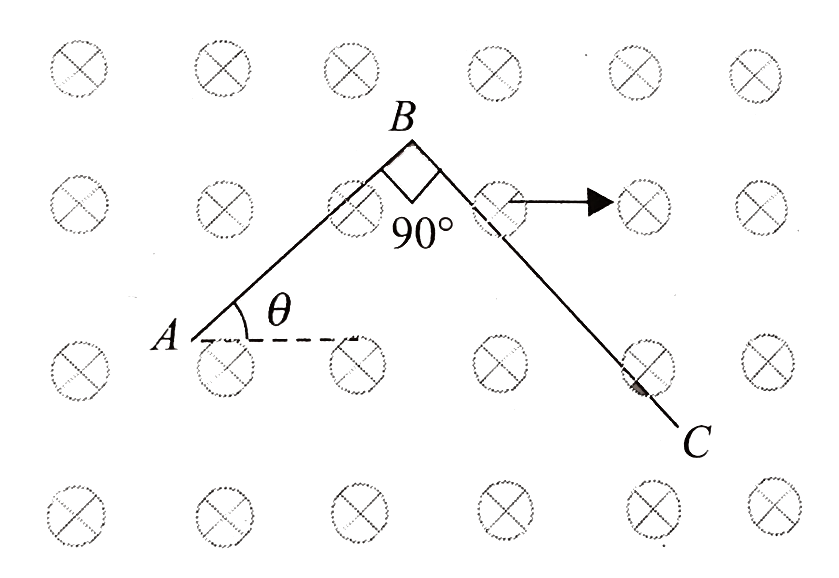
View SolutionA conduting wire ABC (as shown) is moving with a constant velocity along horizontal direction. The magnetic field is perpendicular to the wire and directed into the page. AB =BC. Find the range of angle `(theta)` made by rod AB with horizontal at A so that value of induced emf at A is greater than at C
View SolutionA uniform magnetic field exists in a square of side 2a (as shown in Fig). A square loop of side a centers the field along a diagonal and leave it at a constant speed. Draw the curve between induced emf e and distance along the diagonal, say `x_(0)`

View Solution
Single Correct questions and complete solutions for chapter MISCELLANEOUS VOLUME 5 of CENGAGE PHYSICS (HINGLISH) of Class 12