Complete Solutions to Linked Comprehension of chapter MISCELLANEOUS VOLUME 5 of Class 12 book with complete answers and questions
| Class 12 | PHYSICS |
| Chapter | MISCELLANEOUS VOLUME 5 |
| CENGAGE PHYSICS | Linked Comprehension |
| Number Of Questions | 84 |
| Academic Year | 2023-24 |
An infinite cylindrical wire of radius R and having current density varying with its radius r as, `J = J_(0)[1-(r//R)]`. Then answer the following questions.
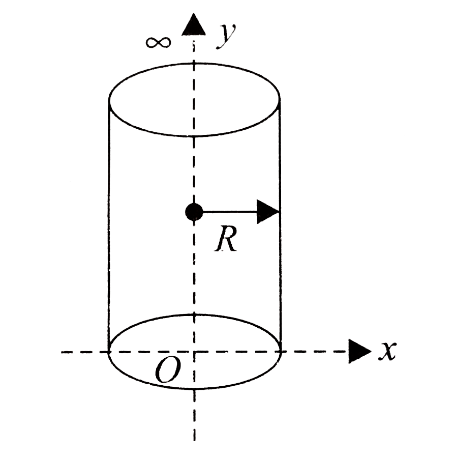
Position where magnetic field strength is maximum.
View SolutionAn infinite cylindrical wire of radius R and having current density varying with its radius r as, `J = J_(0)[1-(r//R)]`. Then answer the following questions.
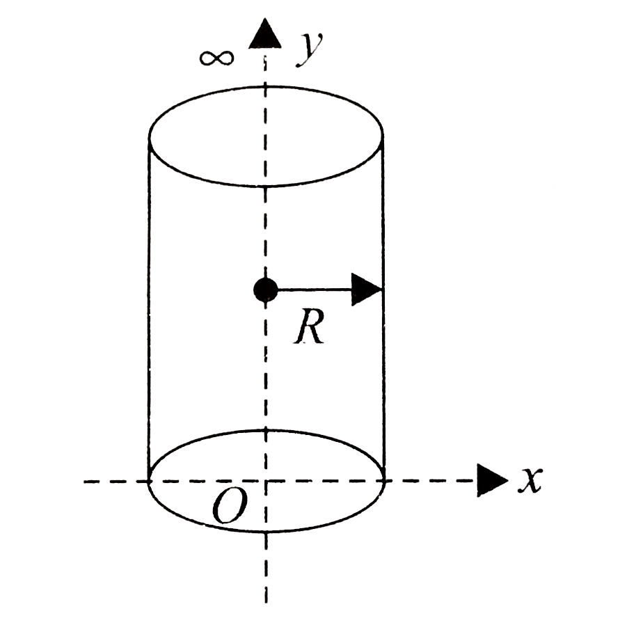
Magnitude of maximum magnetic field is
View SolutionAn infinite cylindrical wire of radius R and having current density varying with its radius r as, `J = J_(0)[1-(r//R)]`. Then answer the following questions.
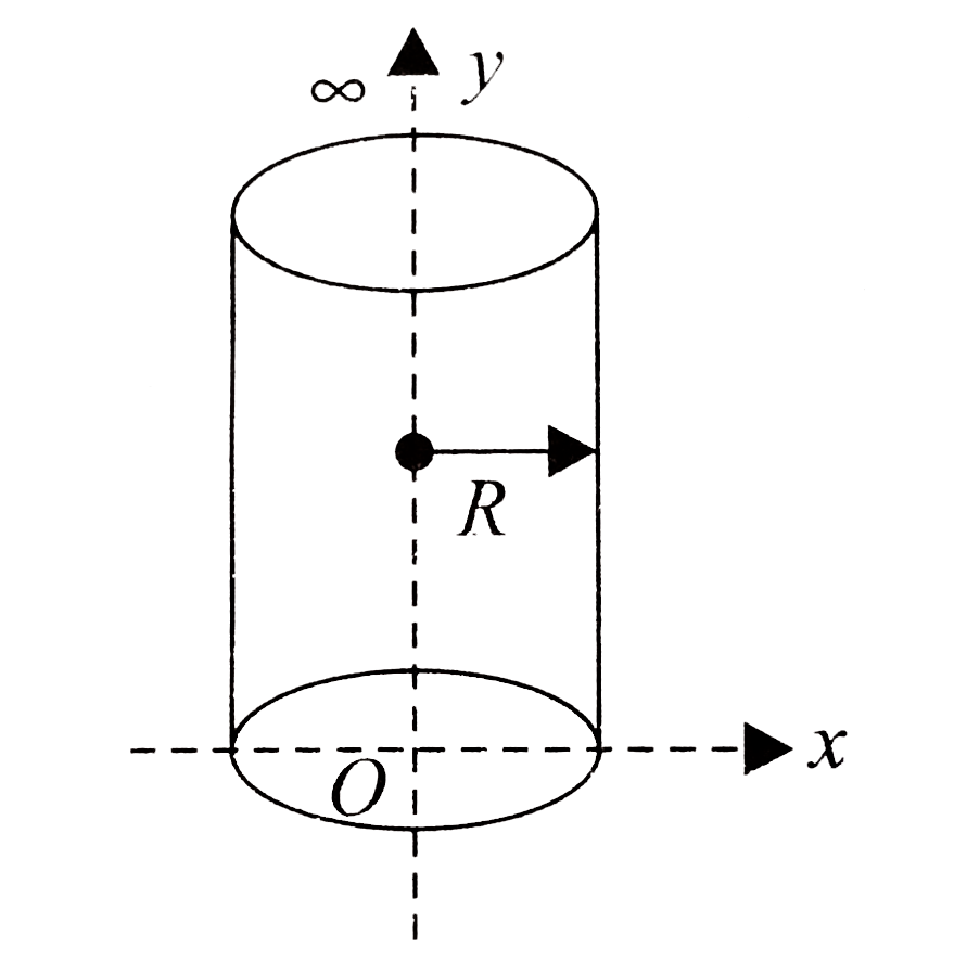
Graph between the magnetic field and radius is
View SolutionA closed current-carrying loop having a current I is having area A. Magnetic moment of this loop is defined as `vec(mu) = vec(IA)` where direction of area vector is towards the observer if current is flowing in anticlockwise direction with respect to the observer. If this loop is placed in a uniform magnetic field `vec(B)`, then torque acting on the loop is given by `vec(tau) = vec(mu) xx vec(B)`. Now answer the following questions:
A uniformly charged insulating ring is rotated in a uniform magnetic field about its own axis, then
View SolutionA closed current-carrying loop having a current I is having area A. Magnetic moment of this loop is defined as `vec(mu) = vec(IA)` where direction of area vector is towards the observer if current is flowing in anticlockwise direction with respect to the observer. If this loop is placed in a uniform magnetic field `vec(B)`, then torque acting on the loop is given by `vec(tau) = vec(mu) xx vec(B)`. Now answer the following questions:
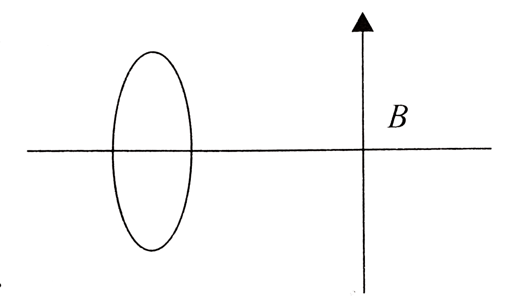
Consider the situation shown in Fig., ring is having a uniformly distributed positive charge. Magnetic field is perpendicular to the axis of ring. Now ring is rotated in anticlockwise direction as seen from left hand side direction of magnetic torque acting on the ring is
View SolutionA closed current-carrying loop having a current I is having area A. Magnetic moment of this loop is defined as `vec(mu) = vec(IA)` where direction of area vector is towards the observer if current is flowing in anticlockwise direction with respect to the observer. If this loop is placed in a uniform magnetic field `vec(B)`, then torque acting on the loop is given by `vec(tau) = vec(mu) xx vec(B)`. Now answer the following questions:
Let ring in the above question is having a radius R and a charge Q is uniformly distributed over it. Ring is rotated with a constant angular velocity `(omega)` as mentioned above.
Torque acting on the ring due to magnetic force is
View SolutionA charged particle with charge to mass ratio `((q)/(m)) = (10)^(3)/(19) Ckg^(-1)` enters a uniform magnetic field `vec(B) = 20 hat(i) + 30 hat(j) + 50 hat(k) T` at time t = 0 with velocity `vec(V) = (20 hat(i) + 50 hat(j) + 30 hat(k)) m//s`. Assume that magnetic field exists in large space.
During the further motion of the particle in the magnetic field, the angle between the magnetic field and velocity of the particle
View SolutionA charged particle with charge to mass ratio `((q)/(m)) = (10)^(3)/(19) Ckg^(-1)` enters a uniform magnetic field `vec(B) = 20 hat(i) + 30 hat(j) + 50 hat(k) T` at time t = 0 with velocity `vec(V) = (20 hat(i) + 50 hat(j) + 30 hat(k)) m//s`. Assume that magnetic field exists in large space.
The frequency (in Hz) of the revolution of the particle in cycles per second will be
View SolutionA charged particle with charge to mass ratio `((q)/(m)) = (10)^(3)/(19) Ckg^(-1)` enters a uniform magnetic field `vec(B) = 20 hat(i) + 30 hat(j) + 50 hat(k) T` at time t = 0 with velocity `vec(V) = (20 hat(i) + 50 hat(j) + 30 hat(k)) m//s`. Assume that magnetic field exists in large space.
The pitch of the helical path of the motion of the particle will be
View SolutionPQRS is a square region of side 2a in the plane of paper. A uniform magnetic field B, directed perpendicular to the plane of paper and into its plane is confined within this square region. A square loop of side 'a' and made of a conducting wire of resistance R is moved at a constant velocity `vec(v)` from left to right in the plane of paper as shown. Obviously, the square loop will enter the magnetic field at some time and then leave it after some time. During the motion of loop, whenever magnetic flux through it changes, emf will be induced resulting in induced current. Let the motion of the square loop be along x-axis and let us measure x coordinate of the centre of square loop from the centre of the square magnetic field region (taken as origin). Thus, x coordinate will be positive if the centre of square loop is to the right of the origin O (centre of magnetic field) and negative if centre is to the left.
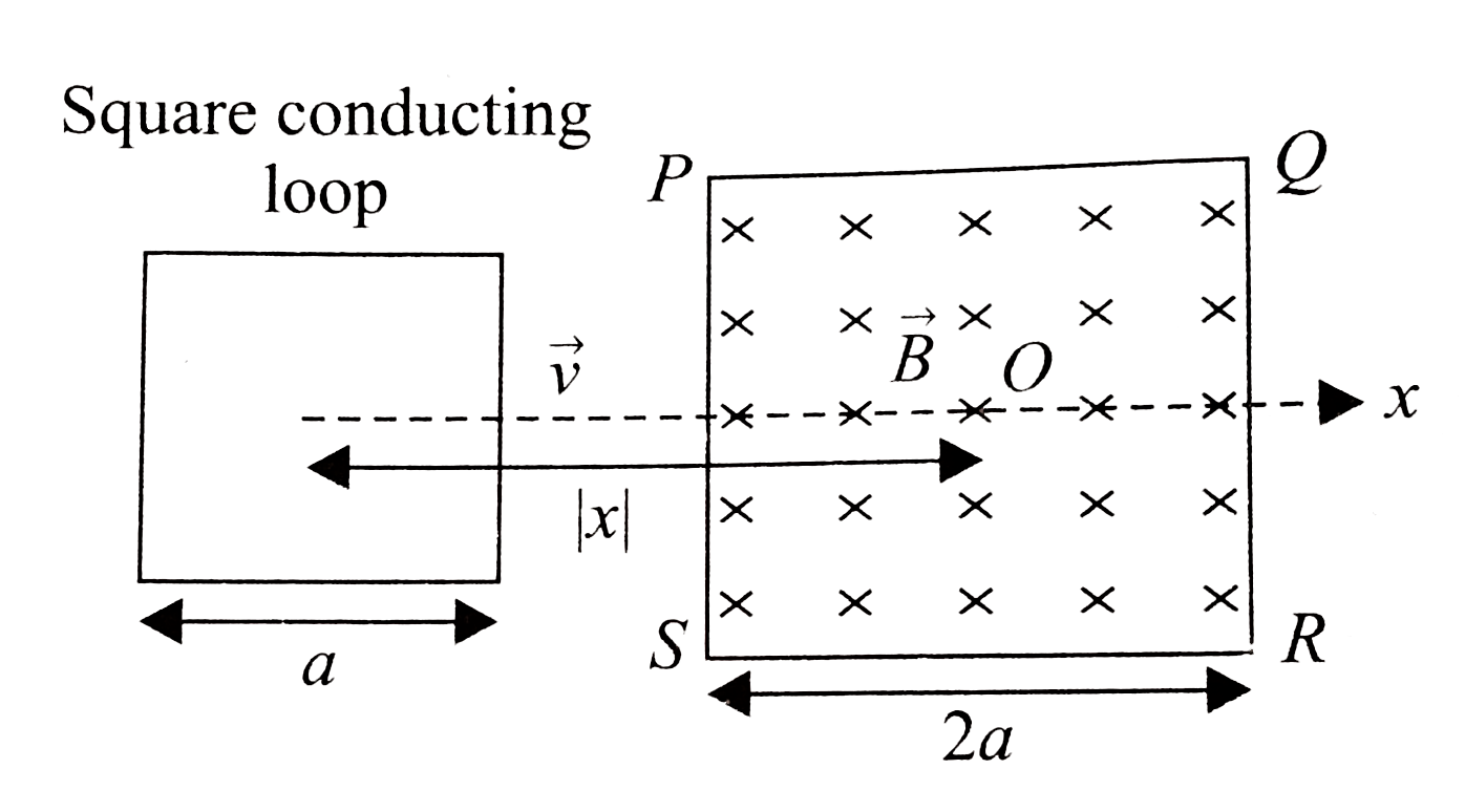
For `x = -9a//5`, magnitude of induced current and its direction as seen from above will be:
View SolutionPQRS is a square region of side 2a in the plane of paper. A uniform magnetic field B, directed perpendicular to the plane of paper and into its plane is confined within this square region. A square loop of side 'a' and made of a conducting wire of resistance R is moved at a constant velocity `vec(v)` from left to right in the plane of paper as shown. Obviously, the square loop will enter the magnetic field at some time and then leave it after some time. During the motion of loop, whenever magnetic flux through it changes, emf will be induced resulting in induced current. Let the motion of the square loop be along x-axis and let us measure x coordinate of the centre of square loop from the centre of the square magnetic field region (taken as origin). Thus, x coordinate will be positive if the centre of square loop is to the right of the origin O (centre of magnetic field) and negative if centre is to the left.
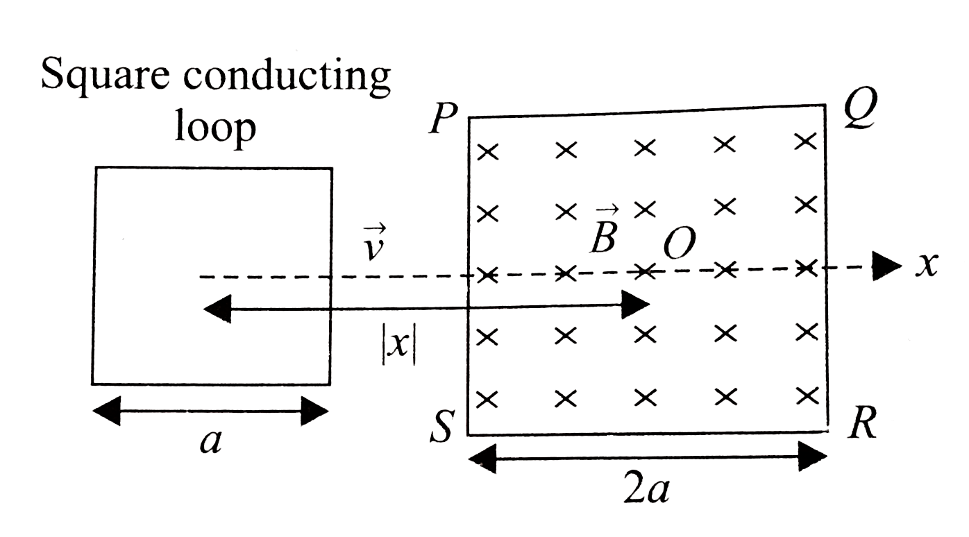
External force required to maintain constant velocity of the loop for `x = -(9)/(5) a` will be
View SolutionPQRS is a square region of side 2a in the plane of paper. A uniform magnetic field B, directed perpendicular to the plane of paper and into its plane is confined within this square region. A square loop of side 'a' and made of a conducting wire of resistance R is moved at a constant velocity `vec(v)` from left to right in the plane of paper as shown. Obviously, the square loop will enter the magnetic field at some time and then leave it after some time. During the motion of loop, whenever magnetic flux through it changes, emf will be induced resulting in induced current. Let the motion of the square loop be along x-axis and let us measure x coordinate of the centre of square loop from the centre of the square magnetic field region (taken as origin). Thus, x coordinate will be positive if the centre of square loop is to the right of the origin O (centre of magnetic field) and negative if centre is to the left.
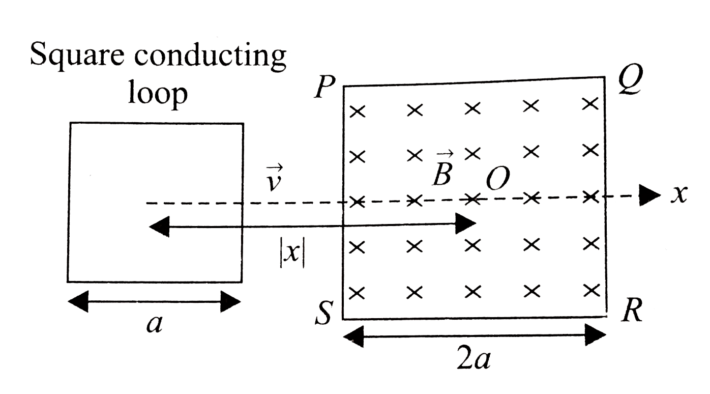
For `x = a//4`
(i) magnetic flux through the loop,
(ii) induced current in the loop and
(iii) external force required to maintain constant velocity of the loop, will be
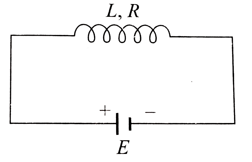
View SolutionAn indcutor having self inductance L with its coil resistance R is connected across a battery of emf `elipson`. When the circuit is in steady state t = 0, an iron rod is inserted into the inductor due to which its inductance becomes nL (ngt1).

After insertion of rod which of the following quantities will change with time?
(1) Potential difference across terminals A and B
(2) Inductance
(3) Rate of heat produced in coil
View SolutionAn indcutor having self inductance L with its coil resistance R is connected across a battery of emf `elipson`. When the circuit is in steady state t = 0, an iron rod is inserted into the inductor due to which its inductance becomes nL (ngt1).

after insertion of rod, current in the circuit:
View SolutionAn indcutor having self inductance L with its coil resistance R is connected across a battery of emf `elipson`. When the circuit is in steady state t = 0, an iron rod is inserted into the inductor due to which its inductance becomes nL (ngt1).

When again circuit is in steady state, the current in it is
View SolutionAs a charged particle 'q' moving with a velocity `vec(v)` enters a uniform magnetic field `vec(B)`, it experience a force `vec(F) = q(vec(v) xx vec(B)). For theta = 0^(@) or 180^(@), theta` being the angle between `vec(v) and vec(B)`, force experienced is zero and the particle passes undeflected. For `theta = 90^(@)`, the particle moves along a circular arc and the magnetic force (qvB) provides the necessary centripetal force `(mv^(2)//r)`. For other values of `theta (theta !=0^(@), 180^(@), 90^(@))`, the charged particle moves along a helical path which is the resultant motion of simultaneous circular and translational motions.
Suppose a particle that carries a charge of magnitude q and has a mass `4 xx 10^(-15)` kg is moving in a region containing a uniform magnetic field `vec(B) = -0.4 hat(k) T`. At some instant, velocity of the particle is `vec(v) = (8 hat(i) - 6 hat(j) 4 hat(k)) xx 10^(6) m s^(-1)` and force acting on it has a magnitude 1.6 N
Motion of charged particle will be along a helical path with
View SolutionAs a charged particle 'q' moving with a velocity `vec(v)` enters a uniform magnetic field `vec(B)`, it experience a force `vec(F) = q(vec(v) xx vec(B)). For theta = 0^(@) or 180^(@), theta` being the angle between `vec(v) and vec(B)`, force experienced is zero and the particle passes undeflected. For `theta = 90^(@)`, the particle moves along a circular arc and the magnetic force (qvB) provides the necessary centripetal force `(mv^(2)//r)`. For other values of `theta (theta !=0^(@), 180^(@), 90^(@))`, the charged particle moves along a helical path which is the resultant motion of simultaneous circular and translational motions.
Suppose a particle that carries a charge of magnitude q and has a mass `4 xx 10^(-15)` kg is moving in a region containing a uniform magnetic field `vec(B) = -0.4 hat(k) T`. At some instant, velocity of the particle is `vec(v) = (8 hat(i) - 6 hat(j) 4 hat(k)) xx 10^(6) m s^(-1)` and force acting on it has a magnitude 1.6 N
Angular frequency of rotation of particle, also called the `cyclotron frequency' is
View SolutionAs a charged particle 'q' moving with a velocity `vec(v)` enters a uniform magnetic field `vec(B)`, it experience a force `vec(F) = q(vec(v) xx vec(B)). For theta = 0^(@) or 180^(@), theta` being the angle between `vec(v) and vec(B)`, force experienced is zero and the particle passes undeflected. For `theta = 90^(@)`, the particle moves along a circular arc and the magnetic force (qvB) provides the necessary centripetal force `(mv^(2)//r)`. For other values of `theta (theta !=0^(@), 180^(@), 90^(@))`, the charged particle moves along a helical path which is the resultant motion of simultaneous circular and translational motions.
Suppose a particle that carries a charge of magnitude q and has a mass `4 xx 10^(-15)` kg is moving in a region containing a uniform magnetic field `vec(B) = -0.4 hat(k) T`. At some instant, velocity of the particle is `vec(v) = (8 hat(i) - 6 hat(j) 4 hat(k)) xx 10^(6) m s^(-1)` and force acting on it has a magnitude 1.6 N
If the coordinates of the particle at t = 0 are (2 m, 1 m, 0), coordinates at a time t = 3 T, where T is the time period of circular component of motion. will be (take `pi = 3.14`)
View SolutionABCDA is a closed loop of conducting wire consisting of two semicircular sections, the part ABCD lying in the XY plane and the part CDA lying in the YZ plane, both the parts having the centre at origin O (see the diagram). This loop is placed in a uniform field `vec(B)` which varies with time.
Radius of the semicircular section is 0.5 m
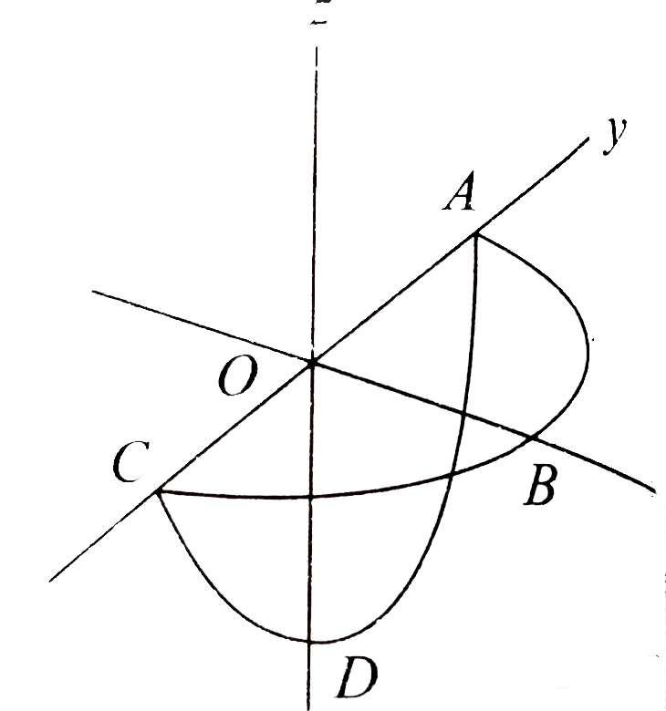
If `vec(B)` be directed along `(+ vec(i) - vec(k))` and decreases at the rate of `10^(-2) Tesla//second`, the magnitude and the sense of the induced emf in the loop, as seen along the magnetic field direction will be
View SolutionABCDA is a closed loop of conducting wire consisting of two semicircular sections, the part ABCD lying in the XY plane and the part CDA lying in the YZ plane, both the parts having the centre at origin O (see the diagram). This loop is placed in a uniform field `vec(B)` which varies with time.
Radius of the semicircular section is 0.5 m
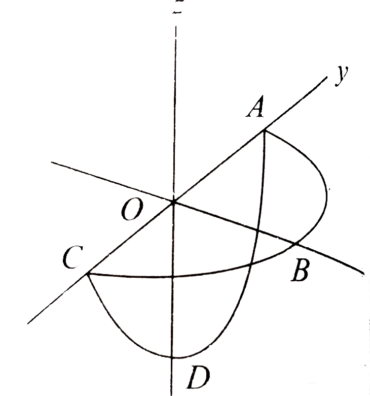
If `vec(B)` be directed along the vector `(vec(i) - vec(j))` and decreases at the rate of `10^(-2) Tesla/second`. The magnitude and sense of the induced emf in the loop as seen along the positive x-axis will be
View SolutionABCDA is a closed loop of conducting wire consisting of two semicircular sections, the part ABCD lying in the XY plane and the part CDA lying in the YZ plane, both the parts having the centre at origin O (see the diagram). This loop is placed in a uniform field `vec(B)` which varies with time.
Radius of the semicircular section is 0.5 m
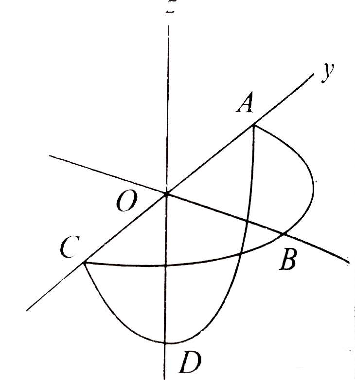
If `vec(B)` be directed along the +z axis and increases at the rate of `10^(-2) ("Tesla")/("second")`. the magnitude and sense of the induced emf in the loop as seen along the field direction will be
View SolutionA solenoid of resistance R and inductance L has a piece of soft iron inside it. A battery of emf E and of negligible internal resistance is connected across the solenoid as shown in Fig. At any instant, the piece of soft iron is pulled out suddenly so that inductance of the solenoid decrease to `etaL(eta lt 1)` with battery remaining connected.
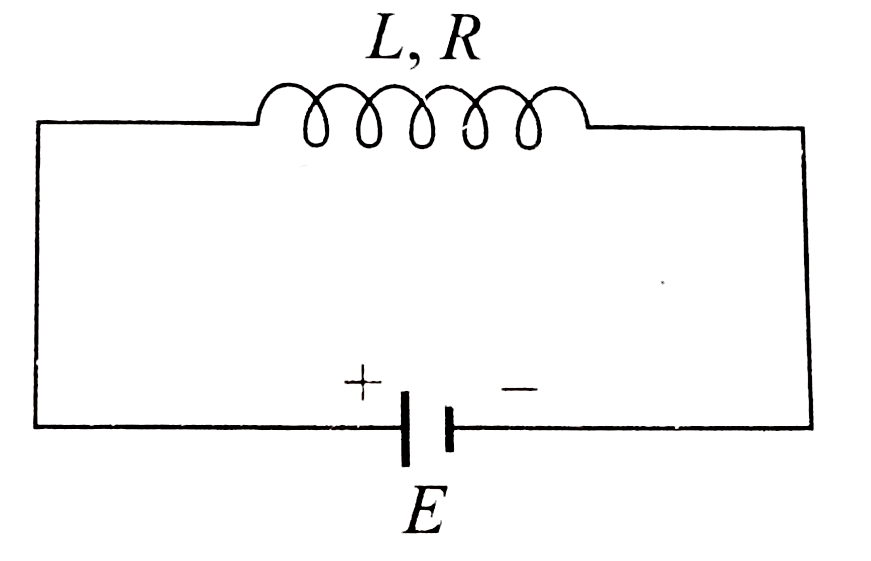
The work done to pull out the soft iron piece is
View SolutionA solenoid of resistance R and inductance L has a piece of soft iron inside it. A battery of emf E and of negligible internal resistance is connected across the solenoid as shown in Fig. At any instant, the piece of soft iron is pulled out suddenly so that inductance of the solenoid decrease to `etaL(eta lt 1)` with battery remaining connected.
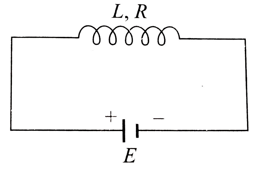
Assume t = 0 is the instant when iron piece has been pulled out, the current as a function of time after this is
View SolutionA solenoid of resistance R and inductance L has a piece of soft iron inside it. A battery of emf E and of negligible internal resistance is connected across the solenoid as shown in Fig. At any instant, the piece of soft iron is pulled out suddenly so that inductance of the solenoid decrease to `etaL(eta lt 1)` with battery remaining connected.
Power supplied by the battery as a function of time
View SolutionThe fact tht a changing magnetic flux produces an electric field is basic to the operation of many high energy particle accelerators. Since the principle was first successfully applied to the acceleration of electrons (or beta particles) in a device called the betatron, this method of acceleration is often given that name. The general idea involved is shown in Fig.
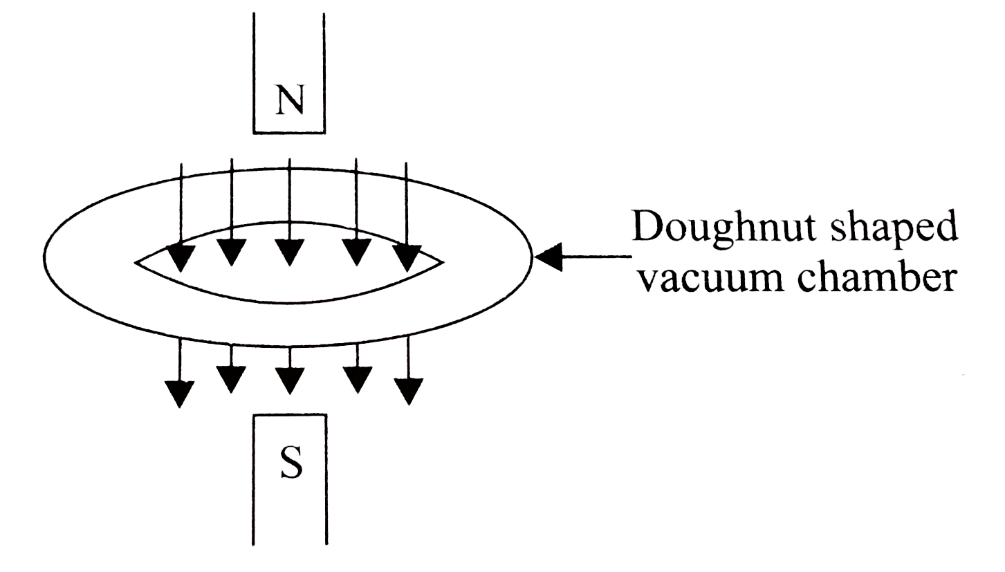
An electromagnet is used to produce a changing flux through a circular loop defined by the doughnut shaped vacuum chamber. We see that there will be an electric field E along the circular length of the doughnut, i.e. circling the magnet poles, given by `2piaE = d(phi)//dt`, where 'a' is the radius of the doughnut. Any charged particle inside the vacuum chamber will experience a force qE and will accelerate. Ordinarily, the charged particle would shoot out the vacuum chamber and becomes lost.
However, if the magnetic field at the position of the doughnut is just proper to satisfy the relation,
Centripetal force = magnetic force or `mv^(2)//a = qvB` then the charge will travel in a circle within the doughnut. By proper shaping of the magnet pole piece, this relation can be satisfied. As a result, the charge will move at high speed along the loop within the doughnut. Each time it goes around the loop, it has, in effect, fallen through a potential difference equal to the induced emf, namely `epsilon = (d(phi)//dt)`. Its energy after 'n' trips around the loop will be `q(n(epsilon))`.
Working of betatron is not based upon which of the following theories?
View SolutionThe fact tht a changing magnetic flux produces an electric field is basic to the operation of many high energy particle accelerators. Since the principle was first successfully applied to the acceleration of electrons (or beta particles) in a device called the betatron, this method of acceleration is often given that name. The general idea involved is shown in Fig.
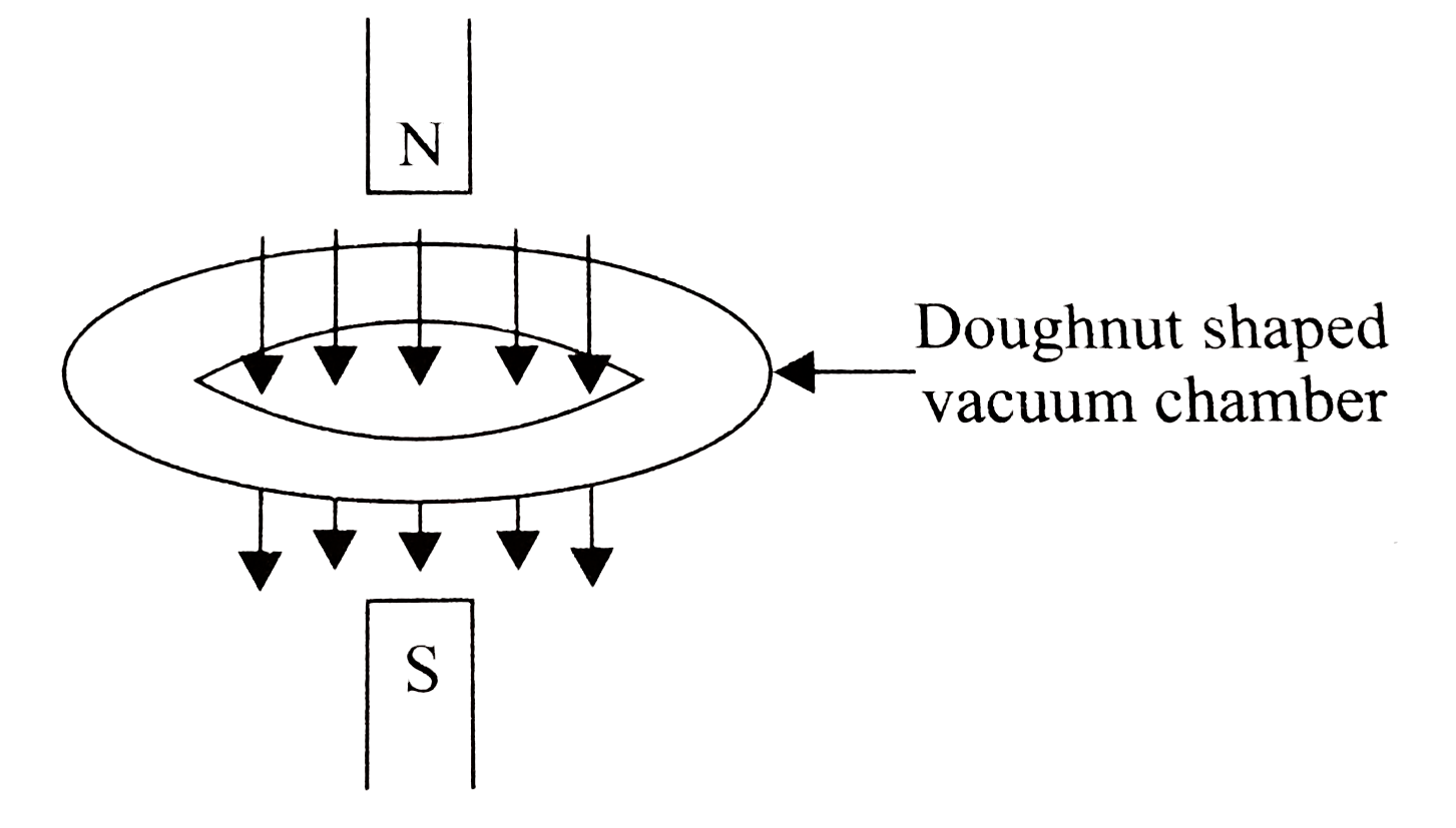
An electromagnet is used to produce a changing flux through a circular loop defined by the doughnut shaped vacuum chamber. We see that there will be an electric field E along the circular length of the doughnut, i.e. circling the magnet poles, given by `2piaE = d(phi)//dt`, where 'a' is the radius of the doughnut. Any charged particle inside the vacuum chamber will experience a force qE and will accelerate. Ordinarily, the charged particle would shoot out the vacuum chamber and becomes lost.
However, if the magnetic field at the position of the doughnut is just proper to satisfy the relation,
Centripetal force = magnetic force or `mv^(2)//a = qvB` then the charge will travel in a circle within the doughnut. By proper shaping of the magnet pole piece, this relation can be satisfied. As a result, the charge will move at high speed along the loop within the doughnut. Each time it goes around the loop, it has, in effect, fallen through a potential difference equal to the induced emf, namely `epsilon = (d(phi)//dt)`. Its energy after 'n' trips around the loop will be `q(n(epsilon))`.
Variable magnetic flux
View SolutionThe fact tht a changing magnetic flux produces an electric field is basic to the operation of many high energy particle accelerators. Since the principle was first successfully applied to the acceleration of electrons (or beta particles) in a device called the betatron, this method of acceleration is often given that name. The general idea involved is shown in Fig.
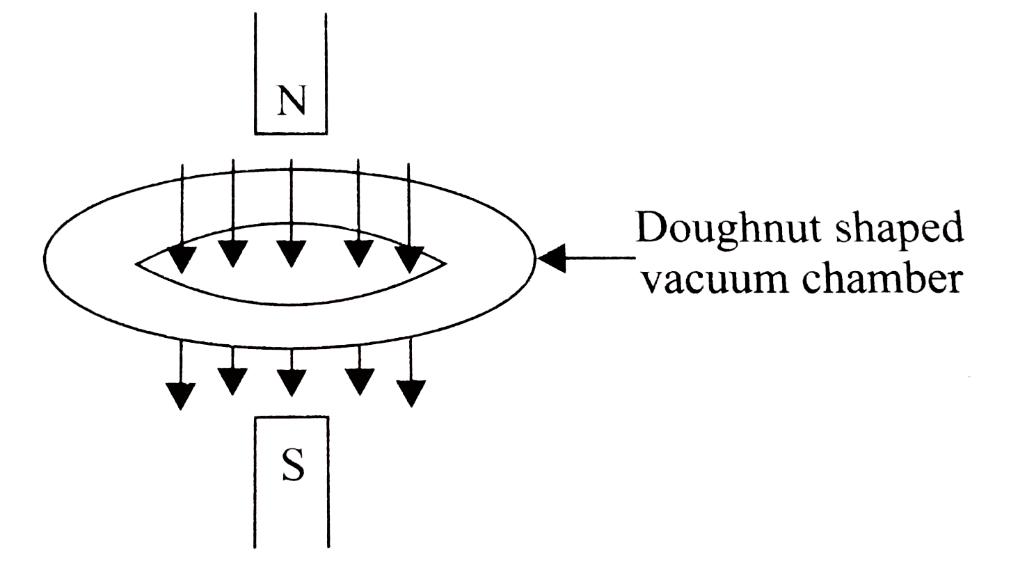
An electromagnet is used to produce a changing flux through a circular loop defined by the doughnut shaped vacuum chamber. We see that there will be an electric field E along the circular length of the doughnut, i.e. circling the magnet poles, given by `2piaE = d(phi)//dt`, where 'a' is the radius of the doughnut. Any charged particle inside the vacuum chamber will experience a force qE and will accelerate. Ordinarily, the charged particle would shoot out the vacuum chamber and becomes lost.
However, if the magnetic field at the position of the doughnut is just proper to satisfy the relation,
Centripetal force = magnetic force or `mv^(2)//a = qvB` then the charge will travel in a circle within the doughnut. By proper shaping of the magnet pole piece, this relation can be satisfied. As a result, the charge will move at high speed along the loop within the doughnut. Each time it goes around the loop, it has, in effect, fallen through a potential difference equal to the induced emf, namely `epsilon = (d(phi)//dt)`. Its energy after 'n' trips around the loop will be `q(n(epsilon))`.
Magnetic field which keeps the particles in circular path must
View SolutionA velocity filter uses the properties of electric and magnetic field to select particles that are moving with a specifice velocity. Charged particles with varying speeds are directed into the filter as shown. The filter consistt of an electric field E and a magnetic field B, each of constant magnitude, directed perpendicular to each other as shown, The charge particles will experience a force due to electric field given by F = qE. If positively charged particles are used, this force is towards right.
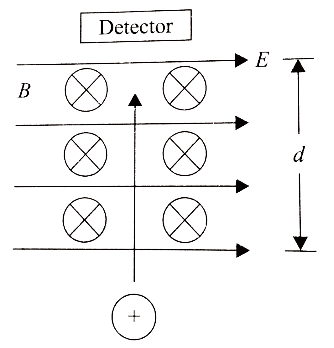
The moving particle will also experience a force due to magnetic field given by `F = qvB`. When forces due to the two fields are of equal magnitude, the net force on the particle will be zero, the particle will pass through centre with its path unaltered. The electric and magnetic fields can be adjusted t choose the specific velocity to be filtered. The efect of gravity can be neglected.
The electric and magnetic fields are adjusted to detect particles with positive charge q of certain speed `v_(0)`. which of the following expressions is equal to this speed?
View SolutionA velocity filter uses the properties of electric and magnetic field to select particles that are moving with a specifice velocity. Charged particles with varying speeds are directed into the filter as shown. The filter consistt of an electric field E and a magnetic field B, each of constant magnitude, directed perpendicular to each other as shown, The charge particles will experience a force due to electric field given by F = qE. If positively charged particles are used, this force is towards right.
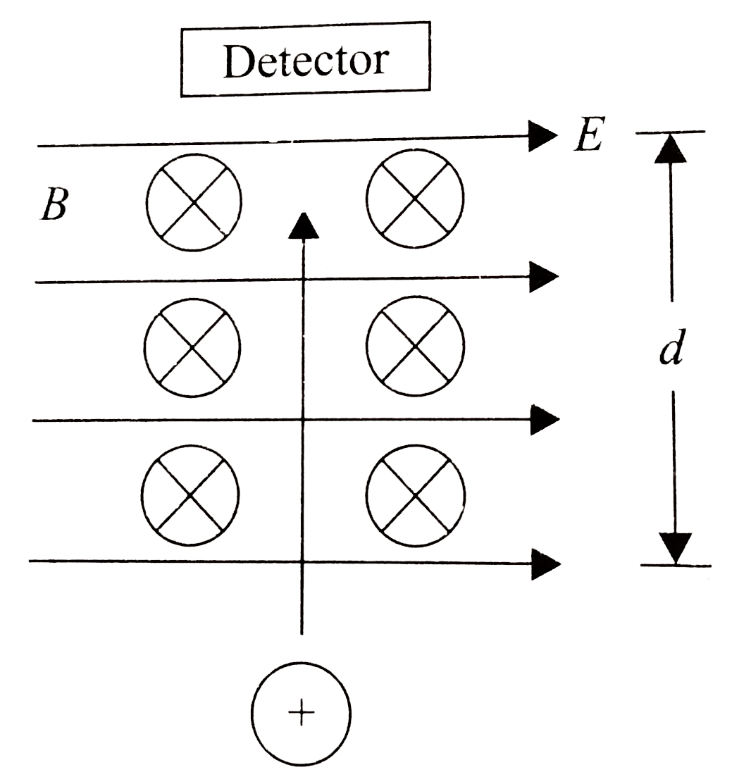
The moving particle will also experience a force due to magnetic field given by F = qvB. When forces due to the two fields are of equal magnitude, the net force on the particle will be zero, the particle will pass through centre with its path unaltered. The electric and magnetic fields can be adjusted t choose the specific velocity to be filtered. The efect of gravity can be neglected.
Which of the following is true about the velocity filter shown in Fig,
View SolutionA velocity filter uses the properties of electric and magnetic field to select particles that are moving with a specifice velocity. Charged particles with varying speeds are directed into the filter as shown. The filter consistt of an electric field E and a magnetic field B, each of constant magnitude, directed perpendicular to each other as shown, The charge particles will experience a force due to electric field given by F = qE. If positively charged particles are used, this force is towards right.
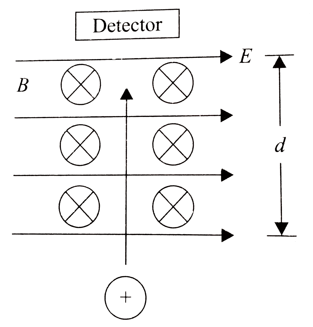
The moving particle will also experience a force due to magnetic field given by F = qvB. When forces due to the two fields are of equal magnitude, the net force on the particle will be zero, the particle will pass through centre with its path unaltered. The electric and magnetic fields can be adjusted t choose the specific velocity to be filtered. The efect of gravity can be neglected.
If the filter is set to detect particles of speed `v_(0)`, which one of the following diagrams best illustrates how the magnitude of the particle acceleration (a) depends on velocity v?
View SolutionIn the given arrangement, the space between a pair of co-axial cylindrical conductors is evacuated. The outer cylinder, called anode, may be given a positive potential V relative to the inner cylinder.
A static homogeneous magnetic field `vec(B)` parallel to the cylinder axis, directed out of plane of figure is aslo present. induced charges in the conductors are neglected.
We study the dynamics of electrons with rest mass m and charge e. The electrons are released at the surface of inner cylinder.
Consider the following two cases
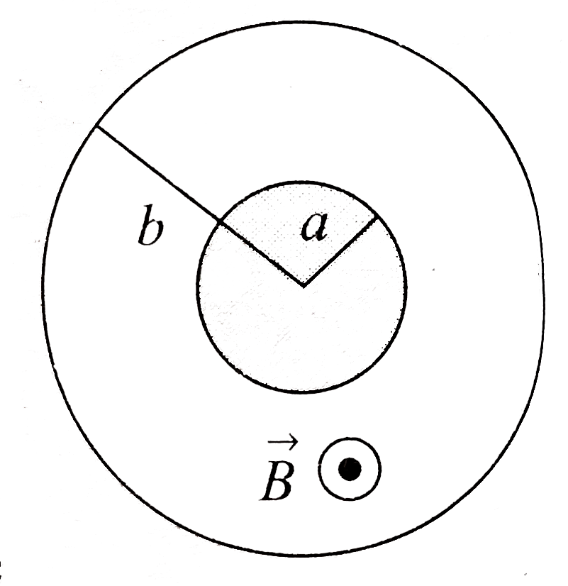
Case 1: Firstly the potential V is turned on, but `vec(B) = 0`. An electron with negligible velocity is ejected at the surface of inner cylinder. It is found to hit the anode.
Case 2: Now V = 0 but `vec(B)` is present. An electron starts out with an initial velocity `vec(v_(0))` in radial direction. For magnetic field larger than critical value `B_(c)` the electron will not reach the anode.
Considering the case 1, the trajectory of electron will be
View SolutionIn the given arrangement, the space between a pair of co-axial cylindrical conductors is evacuated. The outer cylinder, called anode, may be given a positive potential V relative to the inner cylinder.
A static homogeneous magnetic field `vec(B)` parallel to the cylinder axis, directed out of plane of figure is aslo present. induced charges in the conductors are neglected.
We study the dynamics of electrons with rest mass m and charge e. The electrons are released at the surface of inner cylinder.
Consider the following two cases
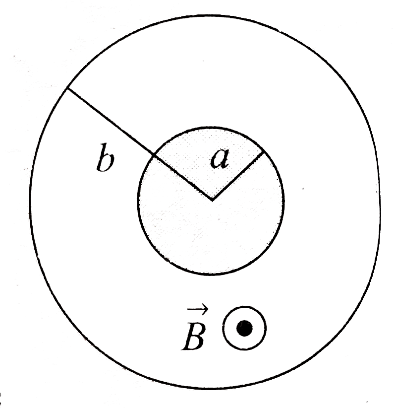
Case 1: Firstly the potential V is turned on, but `vec(B) = 0`. An electron with negligible velocity is ejected at the surface of inner cylinder. It is found to hit the anode.
Case 2: Now V = 0 but `vec(B)` is present. An electron starts out with an initial velocity `vec(v_(0))` in radial direction. For magnetic field larger than critical value `B_(c)` the electron will not reach the anode.
Considering case 2, the trajectory of electron will be
View SolutionIn the given arrangement, the space between a pair of co-axial cylindrical conductors is evacuated. The outer cylinder, called anode, may be given a positive potential V relative to the inner cylinder.
A static homogeneous magnetic field `vec(B)` parallel to the cylinder axis, directed out of plane of figure is aslo present. induced charges in the conductors are neglected.
We study the dynamics of electrons with rest mass m and charge e. The electrons are released at the surface of inner cylinder.
Consider the following two cases
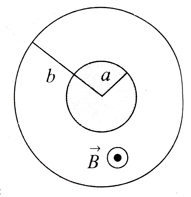
Case 1: Firstly the potential V is turned on, but `vec(B) = 0`. An electron with negligible velocity is ejected at the surface of inner cylinder. It is found to hit the anode.
Case 2: Now V = 0 but `vec(B)` is present. An electron starts out with an initial velocity `vec(v_(0))` in radial direction. For magnetic field larger than critical value `B_(c)` the electron will not reach the anode.
The critical magnetic field `B_(c)` is given by
View SolutionThe path of a charged particle in a uniform magnetic field depends on the angle `theta` between velocity vector and magnetic field, When `theta is 0^(@) or 180^(@), F_(m) = 0` hence path of a charged particle will be linear.
When `theta = 90^(@)`, the magnetic force is perpendicular to velocity at every instant. Hence path is a circle of radius `r = (mv)/(qB)`.
The time period for circular path will be `T = (2pim)/(qB)`
When `theta` is other than `0^(@), 180^(@) and 90^(@)`, velocity can be resolved into two components, one along `vec(B)` and perpendicular to B.
`v_(|/|)=cos theta`
`v_(^)= v sin theta`
The `v_(_|_)` component gives circular path and `v_(|/|)` givestraingt line path. The resultant path is a helical path. The radius of helical path
`r=(mv sin theta)/(qB)`
ich of helix is defined as `P=v_(|/|)T`
`P=(2 i mv cos theta)`
`p=(2 pi mv cos theta)/(qB)`
A charged particle moves in a uniform magnetic field. The velocity of particle at some instant makes acute angle with magnetic field. The path of the particle will be
View SolutionThe path of a charged particle in a uniform magnetic field depends on the angle `theta` between velocity vector and magnetic field, When `theta is 0^(@) or 180^(@), F_(m) = 0` hence path of a charged particle will be linear.
When `theta = 90^(@)`, the magnetic force is perpendicular to velocity at every instant. Hence path is a circle of radius `r = (mv)/(qB)`.
The time period for circular path will be `T = (2pim)/(qB)`
When `theta` is other than `0^(@), 180^(@) and 90^(@)`, velocity can be resolved into two components, one along `vec(B)` and perpendicular to B.
`v_(|/|)=cos theta`
`v_(^)= v sin theta`
The `v_(_|_)` component gives circular path and `v_(|/|)` givestraingt line path. The resultant path is a helical path. The radius of helical path
`r=(mv sin theta)/(qB)`
ich of helix is defined as `P=v_(|/|)T`
`P=(2 i mv cos theta)`
`p=(2 pi mv cos theta)/(qB)`
Two ions having masses in the ratio 1:1 and charges 1:2 are projected from same point into a uniform magnetic field with speed in the ratio 2:3 perpendicular to field. The ratio of radii of circle along which the two particles move is :
View SolutionThe path of a charged particle in a uniform magnetic field depends on the angle `theta` between velocity vector and magnetic field, When `theta is 0^(@) or 180^(@), F_(m) = 0` hence path of a charged particle will be linear.
When `theta = 90^(@)`, the magnetic force is perpendicular to velocity at every instant. Hence path is a circle of radius `r = (mv)/(qB)`.
The time period for circular path will be `T = (2pim)/(qB)`
When `theta` is other than `0^(@), 180^(@) and 90^(@)`, velocity can be resolved into two components, one along `vec(B)` and perpendicular to B.
`v_(|/|)=cos theta`
`v_(^)= v sin theta`
The `v_(_|_)` component gives circular path and `v_(|/|)` givestraingt line path. The resultant path is a helical path. The radius of helical path
`r=(mv sin theta)/(qB)`
ich of helix is defined as `P=v_(|/|)T`
`P=(2 i mv cos theta)`
`p=(2 pi mv cos theta)/(qB)`
Which particle will have minimum frequency of revolution when projected with the same velocity perpendicular to a magnetic field.
View SolutionMagnetic force on a charged particle is given by `vec F_(m) = q(vec(v) xx vec(B))` and electrostatic force `vec F_(e) = q vec (E)`. A particle having charge q = 1C and mass 1 kg is released from rest at origin. There are electric and magnetic field given by `vec(E) = (10 hat(i)) N//C for x = 1.8 m` and `vec(B) = -(5 hat(k)) T` for `1.8 m le x le 2.4 m`
A screen is placed parallel to y-z plane at `x = 3 m`. Neglect gravity forces.
The speed with which the particle will collide the screen is
View SolutionMagnetic force on a charged particle is given by `vec F_(m) = q(vec(v) xx vec(B))` and electrostatic force `vec F_(e) = q vec (E)`. A particle having charge q = 1C and mass 1 kg is released from rest at origin. There are electric and magnetic field given by `vec(E) = (10 hat(i)) N//C for x = 1.8 m` and `vec(B) = -(5 hat(k)) T` for `1.8 m le x le 2.4 m`
A screen is placed parallel to y-z plane at `x = 3 m`. Neglect gravity forces.
y-coordinate of particle where it collides with screen (in meters) is
View SolutionMagnetic force on a charged particle is given by `vec F_(m) = q(vec(v) xx vec(B))` and electrostatic force `vec F_(e) = q vec (E)`. A particle having charge q = 1C and mass 1 kg is released from rest at origin. There are electric and magnetic field given by `vec(E) = (10 hat(i)) N//C for x = 1.8 m` and `vec(B) = -(5 hat(k)) T` for `1.8 m le x le 2.4 m`
A screen is placed parallel to y-z plane at `x = 3 m`. Neglect gravity forces.
Time after which the particle will collide the screen is (in seconds)
View SolutionFollowing experiment was performed by J.J. Thomson in order to measure ratio of charge e and mass m of electron.
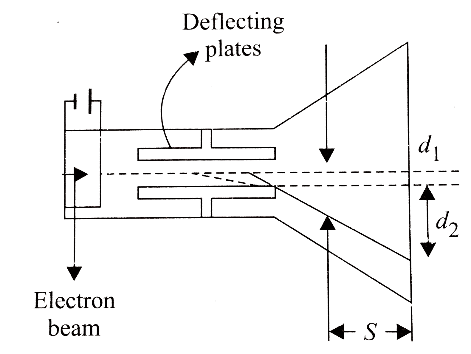
Electrons emitted from a hot filament are accelerated by a potential difference V. As the electrons pass through deflecting plates, they encounter both electric and magnetic fields. the entire region in which electrons leave the plates they enters a field free region that extends to fluorescent screen. The entire region in which electrons travel is evacuated.
Firstly, electric and magnetic fields were made zero and position of undeflected electron beam on the screen was noted. The electric field was turned on and resulting deflection was noted. Deflection is given by `d_(1) = (eEL^(2))/(2mV^(2))` where L = length of deflecting plate and v = speed of electron.
In second part of experiment, magnetic field was adjusted so as to exactly cancel the electric force leaving the electron beam undeflected. This gives eE = evB. Using expression for ` d_(1)` we can find out `(e)/(m) = (2d_(1)E)/(B^(2)L^(2))`
If the electron is deflected downward when only electric field is turned on, in what direction do the electric and magnetic fields point in second part of experiment
View SolutionFollowing experiment was performed by J.J. Thomson in order to measure ratio of charge e and mass m of electron.
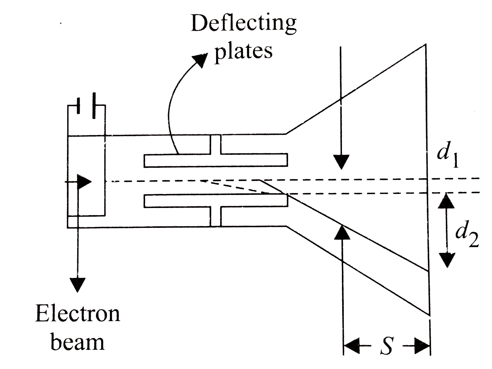
Electrons emitted from a hot filament are accelerated by a potential difference V. As the electrons pass through deflecting plates, they encounter both electric and magnetic fields. the entire region in which electrons leave the plates they enters a field free region that extends to fluorescent screen. The entire region in which electrons travel is evacuated.
Firstly, electric and magnetic fields were made zero and position of undeflected electron beam on the screen was noted. The electric field was turned on and resulting deflection was noted. Deflection is given by `d_(1) = (eEL^(2))/(2mV^(2))` where L = length of deflecting plate and v = speed of electron.
In second part of experiment, magnetic field was adjusted so as to exactly cancel the electric force leaving the electron beam undeflected. This gives `eE = evB`. Using expression for ` d_(1)` we can find out `(e)/(m) = (2d_(1)E)/(B^(2)L^(2))`
A beam of electron with velocity `3 xx 10^(7) m s^(-1)` is deflected 2 mm while passing through 10 cm in an electric field of ` 1800 V//m` perpendicular to its path. `e//m` for electron is
View SolutionFollowing experiment was performed by J.J. Thomson in order to measure ratio of charge e and mass m of electron.
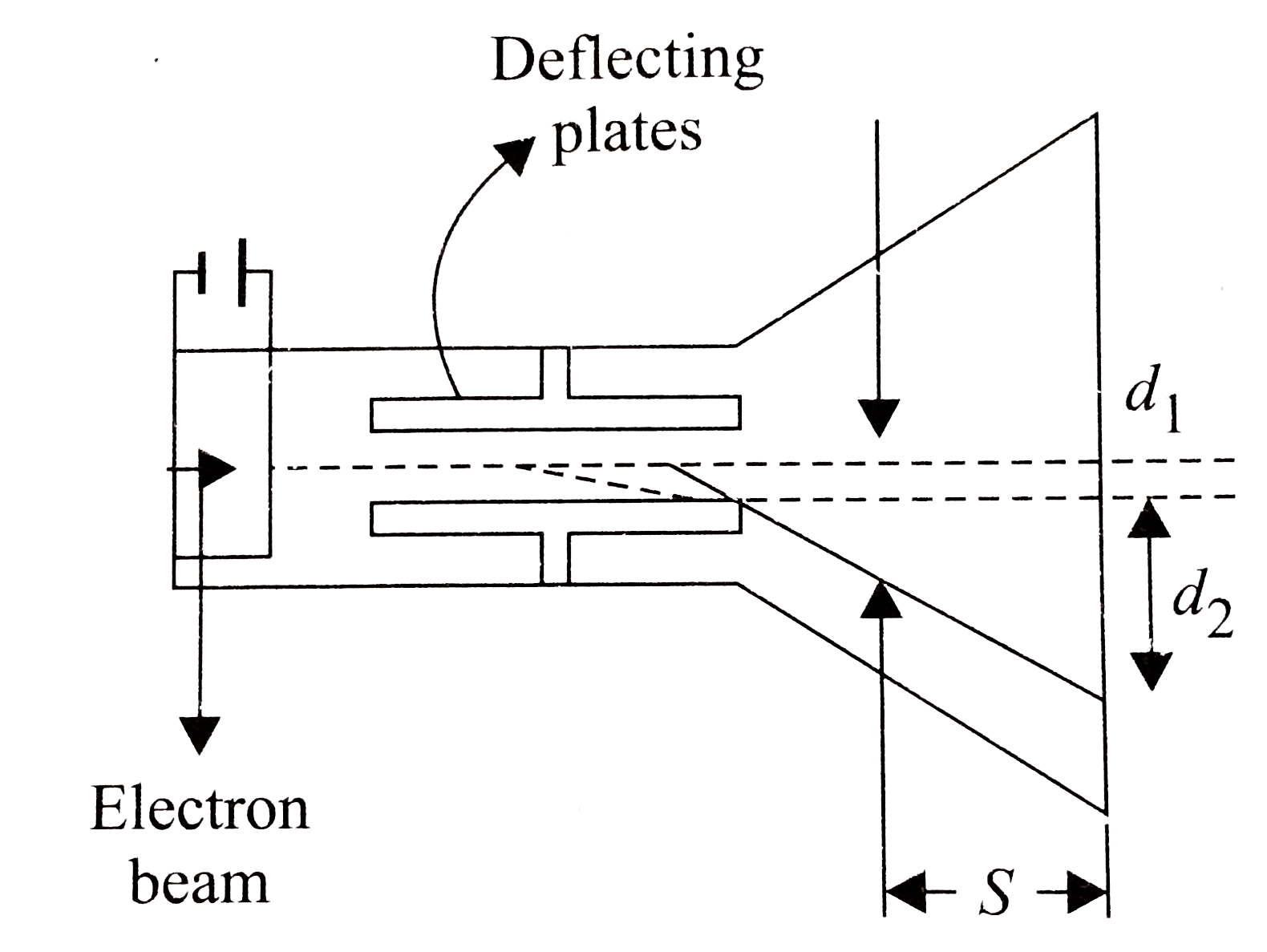
Electrons emitted from a hot filament are accelerated by a potential difference V. As the electrons pass through deflecting plates, they encounter both electric and magnetic fields. the entire region in which electrons leave the plates they enters a field free region that extends to fluorescent screen. The entire region in which electrons travel is evacuated.
Firstly, electric and magnetic fields were made zero and position of undeflected electron beam on the screen was noted. The electric field was turned on and resulting deflection was noted. Deflection is given by `d_(1) = (eEL^(2))/(2mV^(2))` where L = length of deflecting plate and v = speed of electron.
In second part of experiment, magnetic field was adjusted so as to exactly cancel the electric force leaving the electron beam undeflected. This gives `eE = evB`. Using expression for ` d_(1)` we can find out `(e)/(m) = (2d_(1)E)/(B^(2)L^(2))`
If the electron speed were doubled by increasing the potential differece V, which of the following would be true in order to correctly measure `e//m`
View SolutionIn uniform magnetic field, if angle between `vec(v) and vec(B) is 0^(@) lt 0 lt 90^(@)`, the path of particle is helix. Let `v_(1)` be the component of `vec(v) along vec(B) and v_(2)` be the component perpendicular to `vec(B)`. Suppose p is the pitch. T is the time period and r is the radius of helix. Then
`T = (2pim)/(qB), r = (mv_(2))/(qB), P = (v_(1))T`
Assume a charged particle of charge q and mass m is released from the origin with velocity `vec(v) = v_(0) hat(i) - v_(0) hat(k)` in a uniform magnetic field `vec(B) = -B_(0) hat(k)`.
Pitch of helical path described by particle is
View SolutionIn uniform magnetic field, if angle between `vec(v) and vec(B) is 0^(@) lt 0 lt 90^(@)`, the path of particle is helix. Let `v_(1)` be the component of `vec(v) along vec(B) and v_(2)` be the component perpendicular to `vec(B)`. Suppose p is the pitch. T is the time period and r is the radius of helix. Then
`T = (2pim)/(qB), r = (mv_(2))/(qB), P = (v_(1))T`
Assume a charged particle of charge q and mass m is released from the origin with velocity `vec(v) = v_(0) hat(i) - v_(0) hat(k)` in a uniform magnetic field `vec(B) = -B_(0) hat(k)`.
Angle between v and B is
View SolutionIn uniform magnetic field, if angle between `vec(v) and vec(B) is 0^(@) lt 0 lt 90^(@)`, the path of particle is helix. Let `v_(1)` be the component of `vec(v) along vec(B) and v_(2)` be the component perpendicular to `vec(B)`. Suppose p is the pitch. T is the time period and r is the radius of helix. Then
`T = (2pim)/(qB), r = (mv_(2))/(qB), P = (v_(1))T`
Assume a charged particle of charge q and mass m is released from the origin with velocity `vec(v) = v_(0) hat(i) - v_(0) hat(k)` in a uniform magnetic field `vec(B) = -B_(0) hat(k)`.
Axis of helix is along
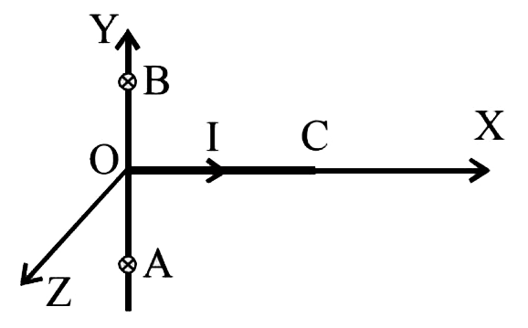
View SolutionA straight segment `OC`(of length L meter) of a circuit carrying a current `I amp` is placed along the ` x- axis` ( fig.). Two infinetely long straight wires ` A and B` , each extending from ` z = -oo to +oo`, are fixed at ` y = -ameter and y = +a meter` respectively, as shown in the figure.
If the wires ` A and B` each carry a current `I amp` into the plane of the paper, obtain the expression for the force acting on the segment ` OC`. What will be the force on `OC` if the current in the wire `B` is reversed?

View SolutionFour long wires each carrying current I as shown in Fig. are placed at points A, B, C and D. Find the magnitude and direction of
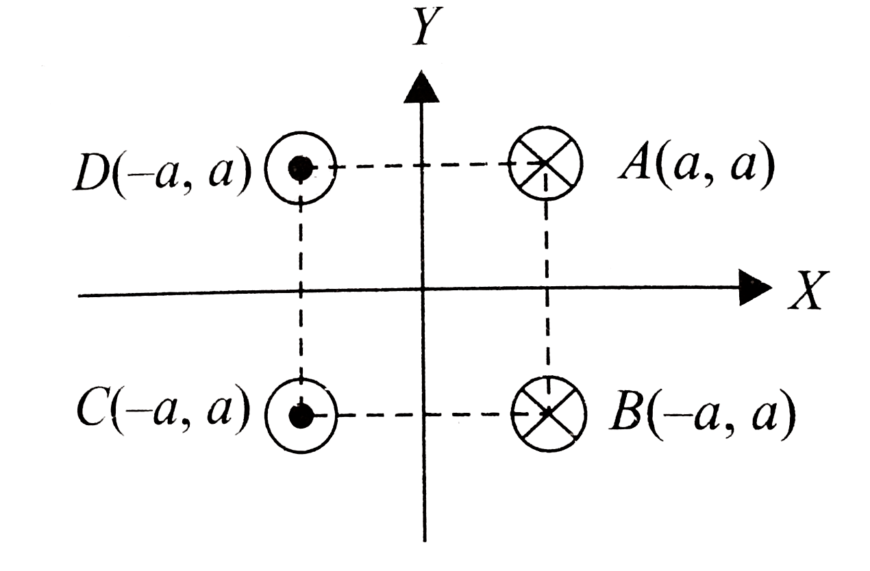
magnetic field at the centre of the square.
View SolutionFour long wires each carrying current I as shown in Fig. are placed at points A, B, C and D. Find the magnitude and direction of
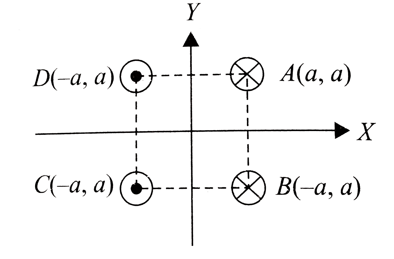
Force per metre acting on wire at point D
View SolutionConsider the situation shown Fig. There present a magnetic field B = 1 T which is perpendicular to plane of paper. The wire `P_(2), Q_(2)` are made to slide on the rails with the same speed `5 cm //s`. Find the electric current in the `19 (Omega)` resistance if
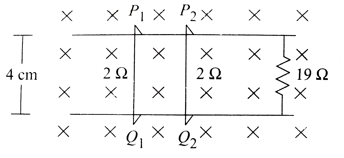
Both the wires move towards right
View SolutionConsider the situation shown in . The wires `P_1Q_1` and `P_2 Q_2` are made to slide on the rails with the same speed `5cm s^(-1)`. Find the electric current in the 19`Omega` resistorif (a) both the wires move towards right and (b) if `P_1 Q_1` moves towards left but `P_2 Q_2` moves towards right.
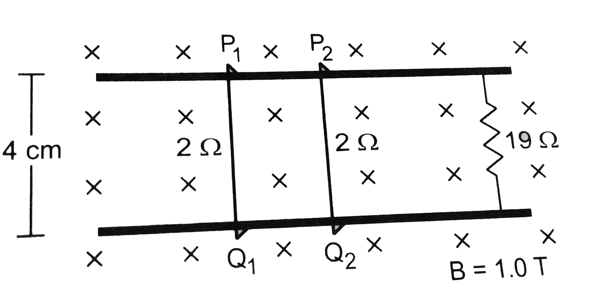
View SolutionSuppose the `19 Omega` resistor of the previous problem is disconnected. Find the current through `P_2 Q_2` in the two situations (a) and (b) of that problem.
View SolutionSuppose the `19 Omega` resistor of the previous problem is disconnected. Find the current through `P_2 Q_2` in the two situations (a) and (b) of that problem.
View SolutionConsider the situation shown in . The wire PQ has a negligible resistance and is made to slide on the three rails with a constant speed of `5 cm s^(-1)` . Find the current in the `10 Omega` resistor when the switch S is thrown to (a) the middle rail (b) the bottom rail.
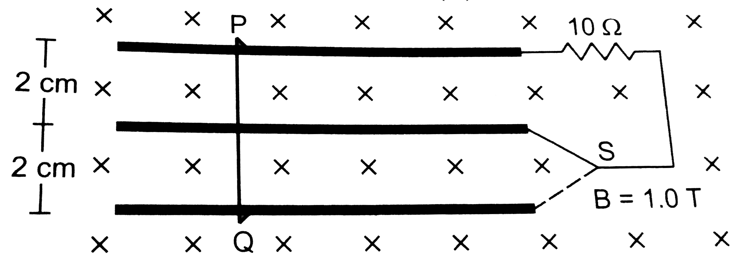
View SolutionConsider the situation shown in . The wire PQ has a negligible resistance and is made to slide on the three rails with a constant speed of `5 cm s^(-1)` . Find the current in the `10 Omega` resistor when the switch S is thrown to (a) the middle rail (b) the bottom rail.

View SolutionA square wire loop with 2 m sides is perpendicular to a uniform magnetic field, with half the area of the loop in the field (see Fig.) The loop contains a 20 V battery with negligible internal resistance. If the magnitude of the field varies with time according to `B = (2 + 5t)`, with B in tesla and t in second.
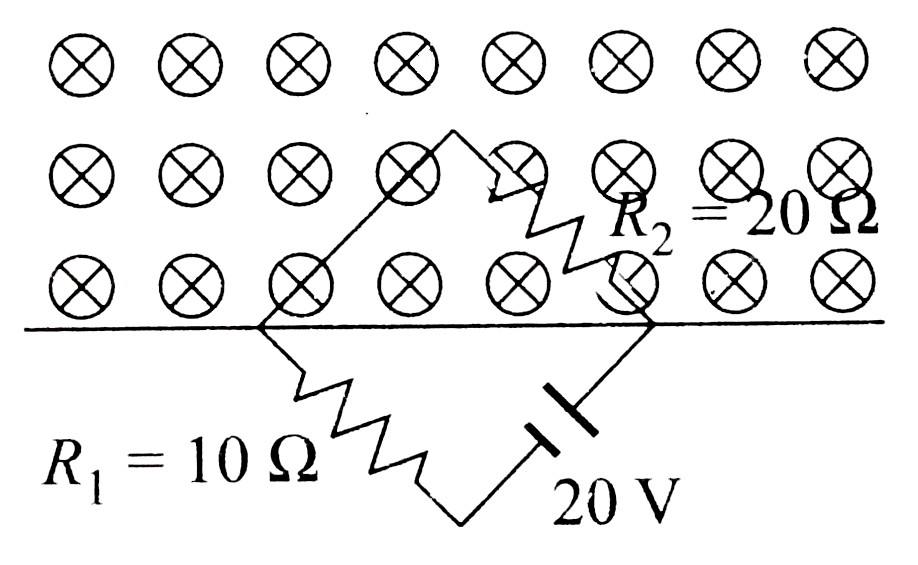
What is the total emf in the circuit ?
View SolutionA square wire loop with 2 m sides is perpendicular to a uniform magnetic field, with half the area of the loop in the field (see Fig.) The loop contains a 20 V battery with negligible internal resistance. If the magnitude of the field varies with time according to B = (2 + 5t), with B in tesla and t in second.
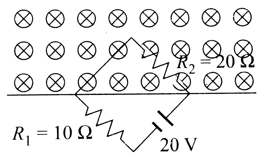
What is the current through the battery ?
View SolutionIn a cylindrical region of radius a, magnetic field exists along its axis but the direction of magnetic field is opposite in the four quadrants of the region as shown in Fig. A or AB rotates with its end A at the centre of magnetic field and other end B slides on a smooth wire at the periphery of the region of magnetic field. At `t = 0` the rod was situated along the +X direction.
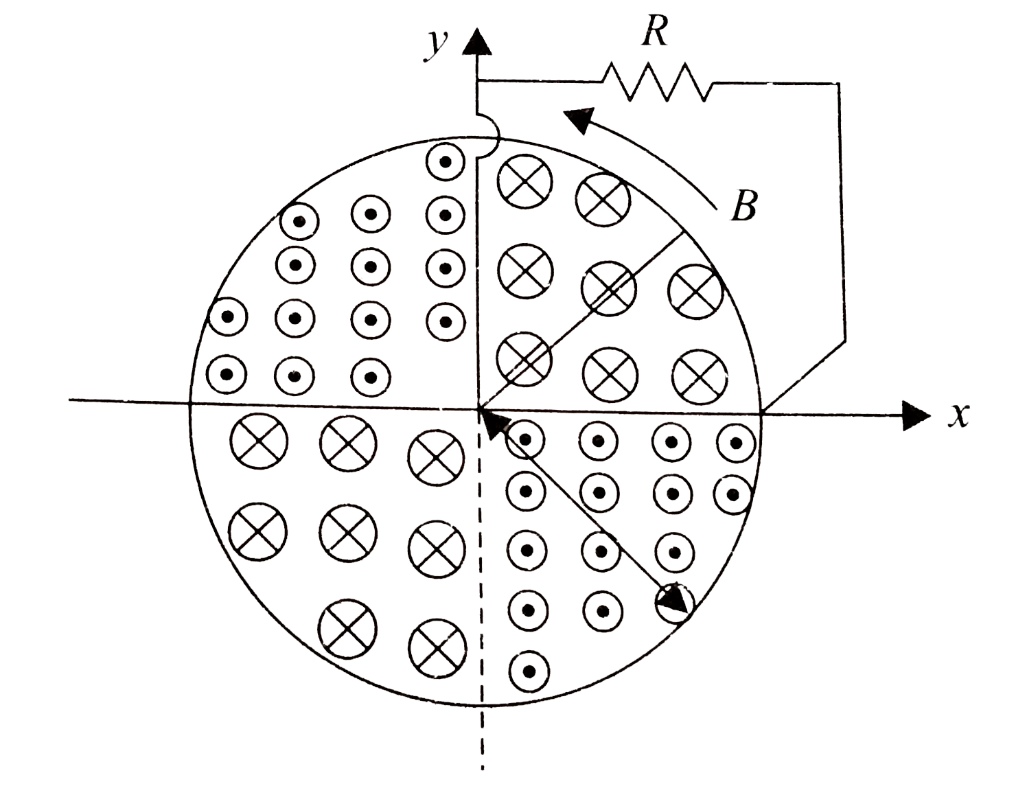
Find and plot the time dependence of the current in the resistance R when rod rotates with a constant angular velocity `(omega)`.
View SolutionIn a cylindrical region of radius a, magnetic field exists along its axis but the direction of magnetic field is opposite in the four quadrants of the region as shown in Fig. A or AB rotates with its end A at the centre of magnetic field and other end B slides on a smooth wire at the periphery of the region of magnetic field. At t = 0 the rod was situated along the +X direction.
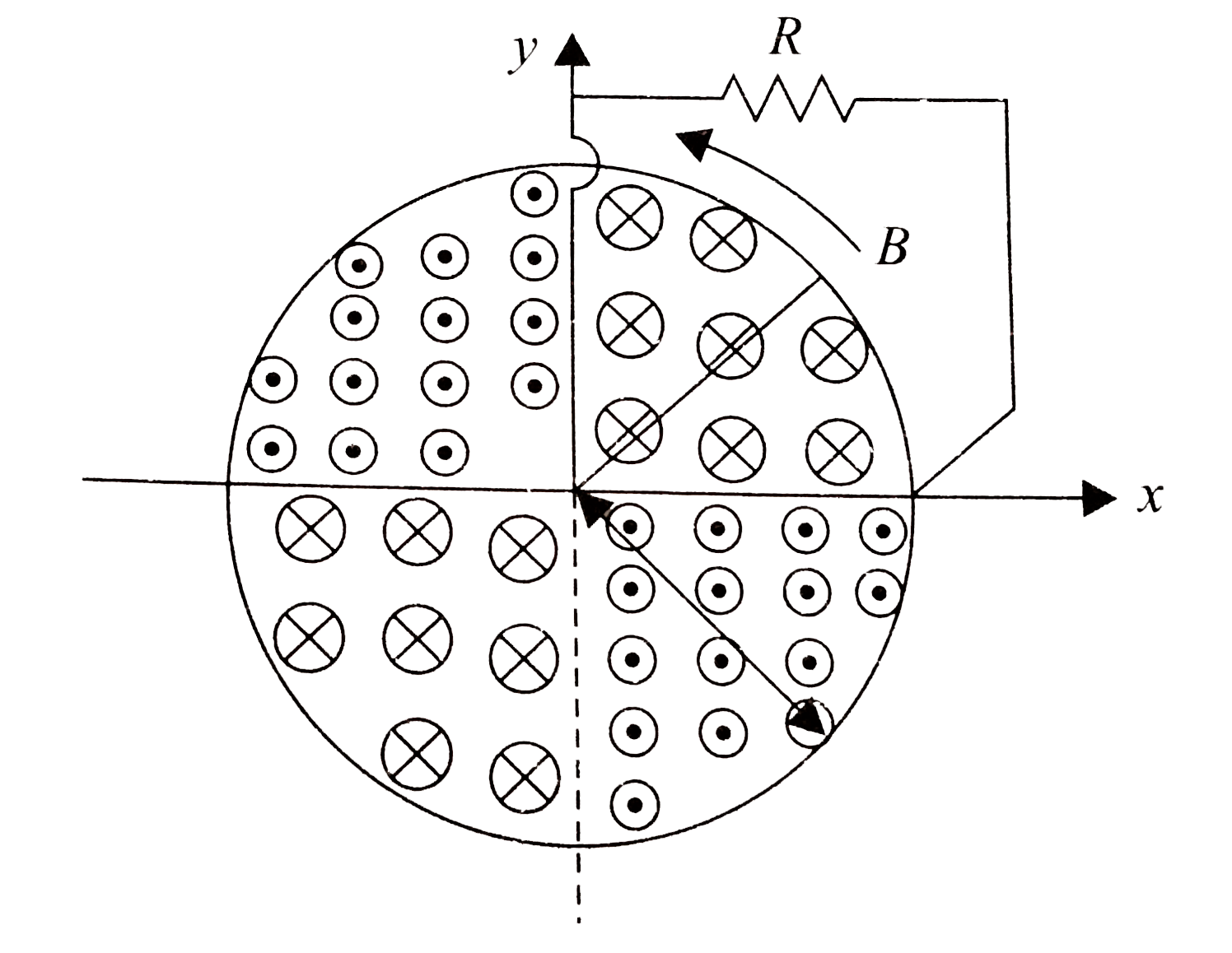
Find and plot the time dependence of the current in the resistance R when rotates with a constant angular acceleration `(alpha)`
View SolutionIn a cylindrical region of radius a, magnetic field exists along its axis but the direction of magnetic field is opposite in the four quadrants of the region as shown in Fig. A or AB rotates with its end A at the centre of magnetic field and other end B slides on a smooth wire at the periphery of the region of magnetic field. At t = 0 the rod was situated along the +X direction.
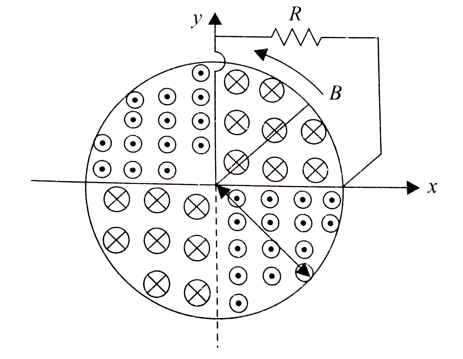
Find and plot the time dependence of the thermal power in the resistance R when rod rotates with a constant angular acceleration `(alpha)`
View SolutionA rectangular wire frame of dimensions `(0.25 xx 2.0 m)` and mass 0.5 kg falls from a height 5m above a region occupied by uniform magnetic field of magnetic induction 1 T. The resistance of the wire frame is `1/8 (Omega)`. Find
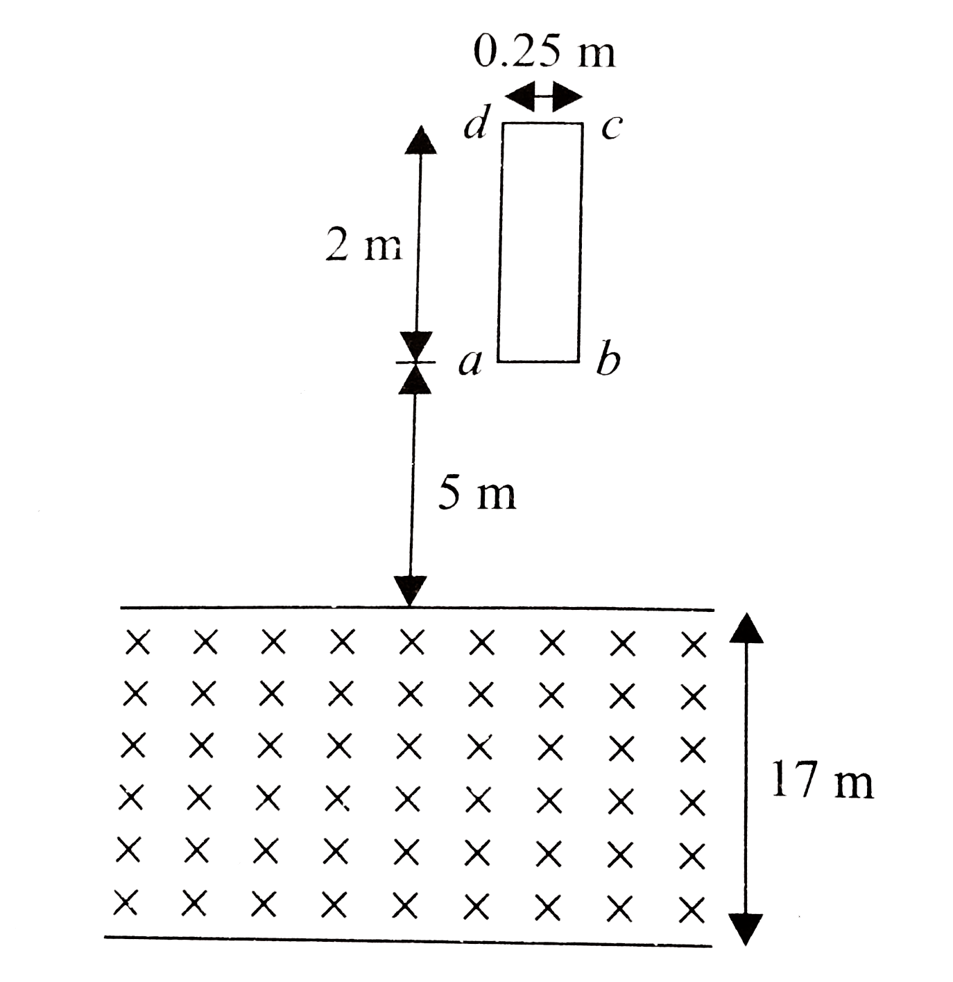
time taken to completely enter into the field is
View SolutionA rectangular wire frame of dimensions `(0.25 xx 2.0 m)` and mass 0.5 kg falls from a height 5m above a region occupied by uniform magnetic field of magnetic induction 1 T. The resistance of the wire frame is `1/8 (Omega)`. Find
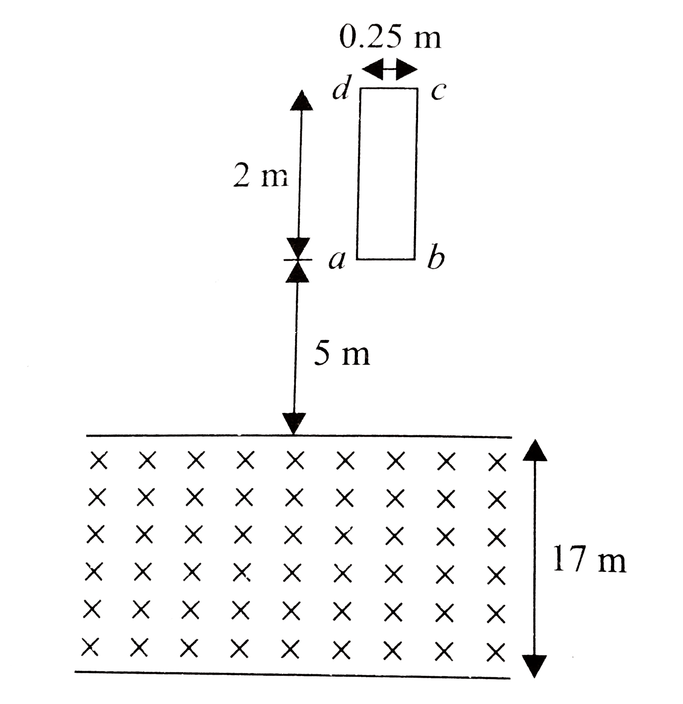
time taken by the wire frame when it just starts coming out of the magnetic field.
View SolutionA metallic rod of mass m and resistance R is sliding over the 2 conducting frictionless rails as shown in Fig. An infinitely long wire carries a current `I_(0)`. The distance of the rails from the wire are b and a respectively.
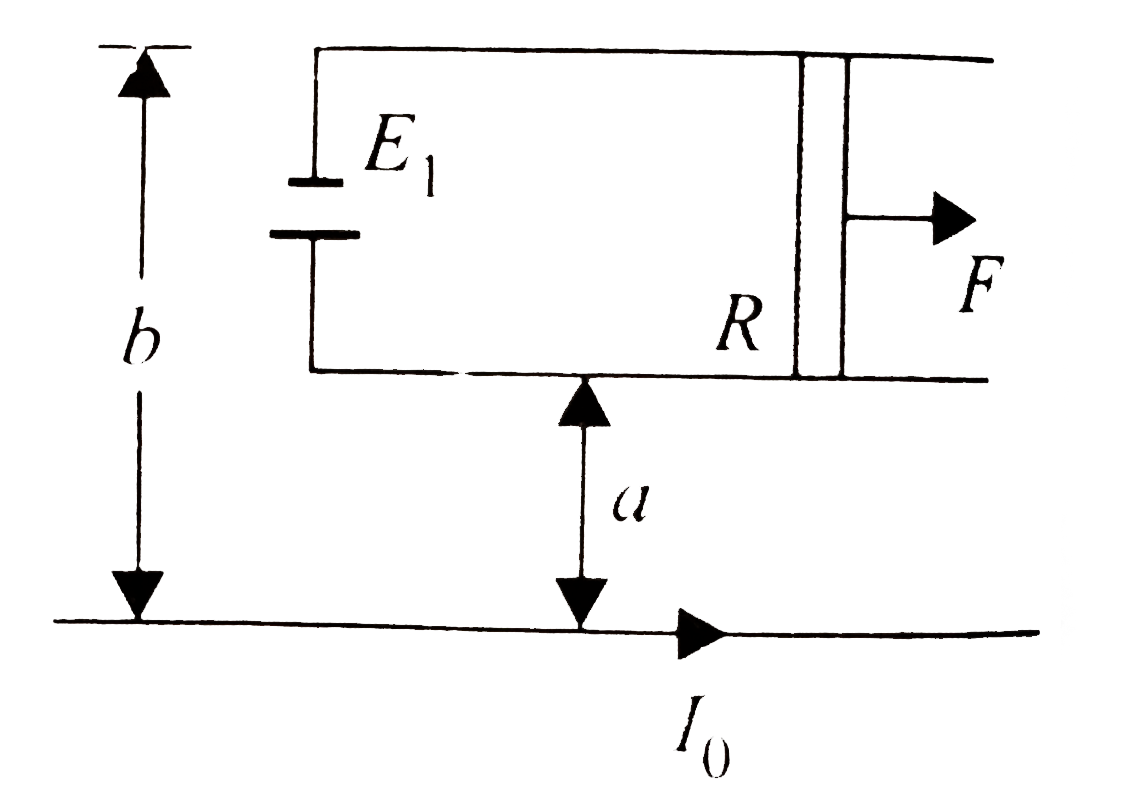
Find the value of current in the circuit if the rod slides with constant velocity `v_(0)`
View SolutionA metallic rod of mass m and resistance R is sliding over the 2 conducting frictionless rails as shown in Fig. An infinitely long wire carries a current `I_(0)`. The distance of the rails from the wire are b and a respectively.
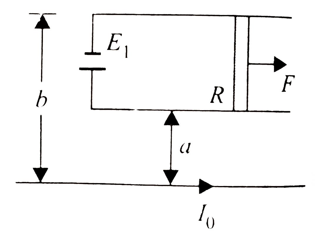
Find the value of F if the rod slides with constant velocity
View SolutionA stationary circular loop of radius a is located in a magnetic field which varies with time from `t = 0 to t = T` according to law `B = B_(0) t(T - t)`. If plane of loop is normal to the direction of field and resistance of the loop is R, calculate
amount of heat generated in the loop during this interval.
View SolutionA stationary circular loop of radius a is located in a magnetic field which varies with time from t = 0 to t = T according to law `B = B_(0) t(T - t)`. If plane of loop is normal to the direction of field and resistance of the loop is R, calculate
magnitude of charge flown through the loop from instant t = 0 to the instant when current reverses its direction.
View SolutionA circular ring of radius a is made from a wire having resistance `(lambda)` per unit length. The ring is mounted on a car such that ring remains vertical. The care moves along a horizontal circle of radius R and completes n revolutions per minute. The horizontal component of earth's magnetic field be H,
The emf induced in the ring is
View SolutionA circular ring of radius a is made from a wire having resistance `(lambda)` per unit length. The ring is mounted on a car such that ring remains vertical. The care moves along a horizontal circle of radius R and completes n revolutions per minute. The horizontal component of earth's magnetic field be H,
Calculate average rate at which heat is produced in the ring
View SolutionA long solenoid having n = 200 turns per metre has a circular cross-section of radius `a_(1) = 1 cm`. A circular conducting loop of radius `a_(2) = 4 cm` and resistance ` R = 5 (Omega)` encircles the solenoid such that the centre of circular loop coincides with the midpoint of the axial line of the solenoid and they have the same axis as shown in Fig.
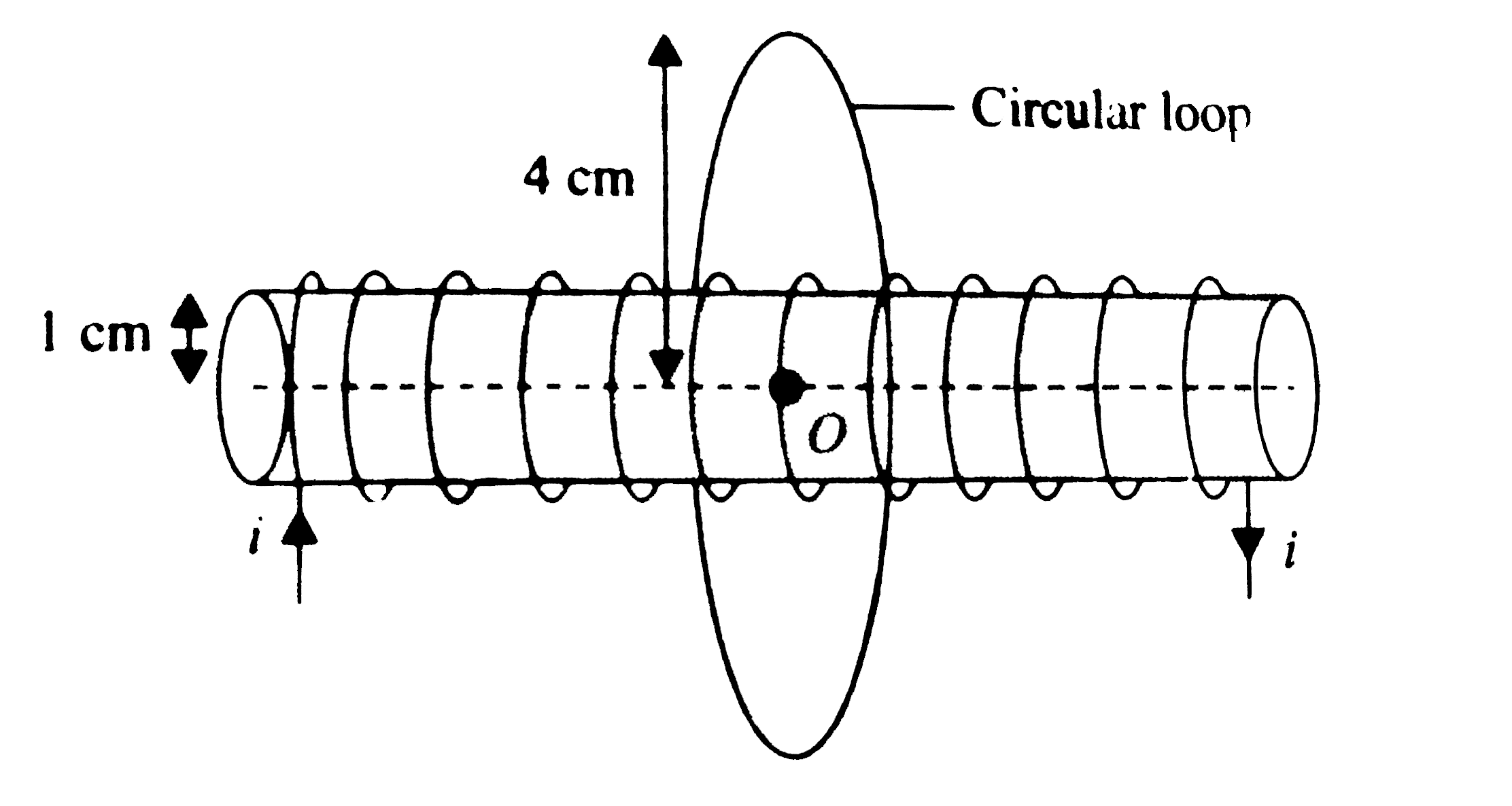
A current 't' in the solenoid results in magnetic field along its axis with magnitude `B = (mu)ni` at points well inside the solenoid on its axis. We can neglect the insignificant field outside the solenoid. This results in a magnetic flux `(phi)_(B)` through the circular loop. If the current in the winding of solenoid is changed, it will also change the magnetic field `B = (mu)_(0)ni` and hence also the magnetic flux through the circular loop. Obvisouly, it will result in an induced emf or induced electric field in the circular loop and an induced current will appear in the loop. Let current in the winding of solenoid be reduced at a rate of `75 A //sec`.
Magnitude of induced current that appears in the circular loop is
View SolutionA long solenoid having n = 200 turns per metre has a circular cross-section of radius `a_(1) = 1 cm`. A circular conducting loop of radius `a_(2) = 4 cm` and resistance ` R = 5 (Omega)` encircles the solenoid such that the centre of circular loop coincides with the midpoint of the axial line of the solenoid and they have the same axis as shown in Fig.
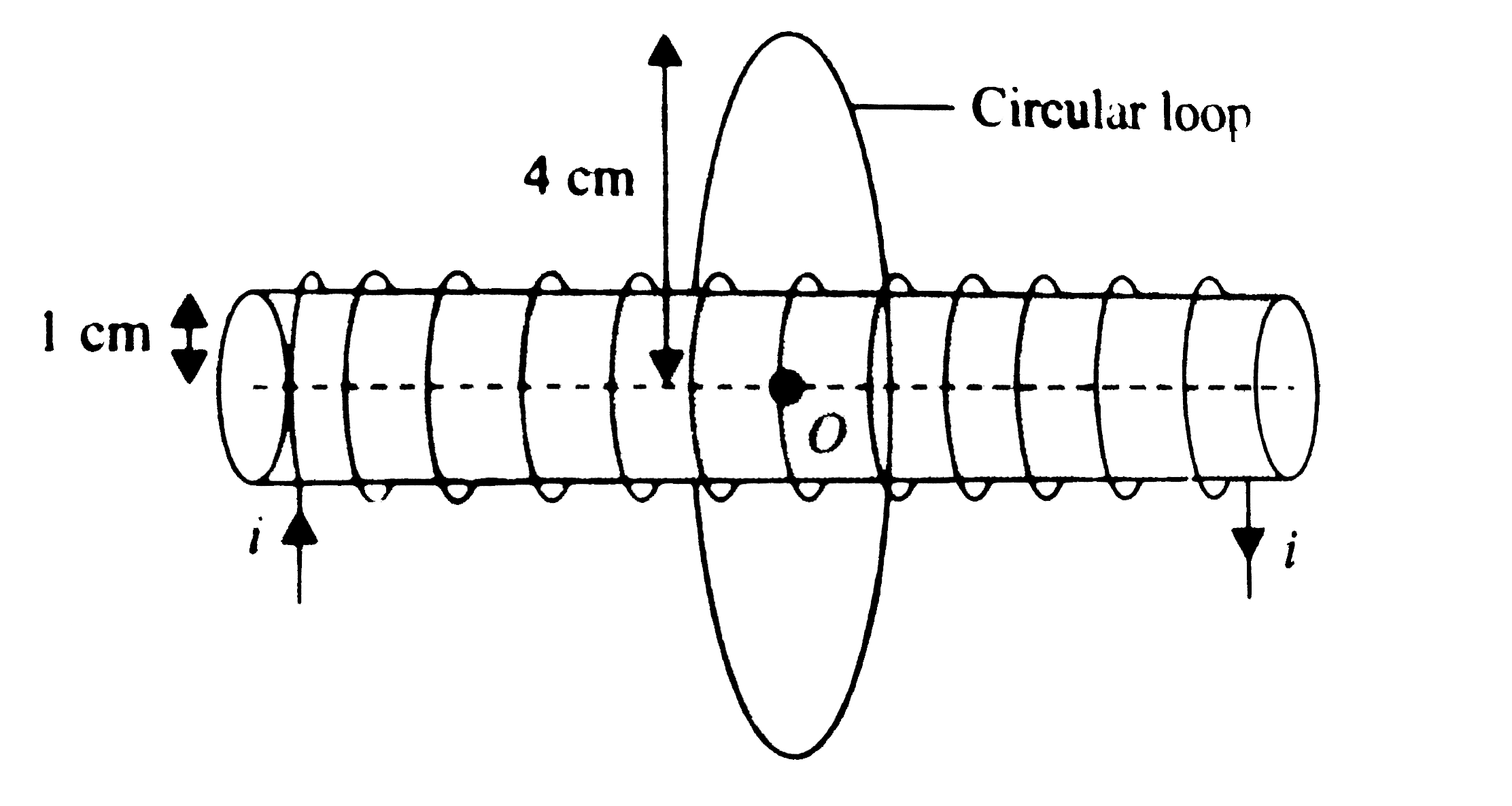
A current 't' in the solenoid results in magnetic field along its axis with magnitude `B = (mu)ni` at points well inside the solenoid on its axis. We can neglect the insignificant field outside the solenoid. This results in a magnetic flux `(phi)_(B)` through the circular loop. If the current in the winding of solenoid is changed, it will also change the magnetic field `B = (mu)_(0)ni` and hence also the magnetic flux through the circular loop. Obvisouly, it will result in an induced emf or induced electric field in the circular loop and an induced current will appear in the loop. Let current in the winding of solenoid be reduced at a rate of `75 A //sec`.
Magnetic of induced electric field strength in the circular loop is nearly We know that there is magnetic flux through the circular loop because of the magnetic field of current in the solenoid. For the purpose of circular loop, let us call it the external magnetic field. As current in the solenoid is reducing, external magnetic field for the circular loop also reduced resulting in induced current in the loop. Finally, as the solenoid current becomes zero, external field for the loop also becomes zero and stop changing. However, induced current in the loop will not stop at the instant at which the external field stops changing. This is because induced current itself produces a magnetic field that results in a flux through the loop. External field becoming zero without any further change will compel the induced current in the loop to become zero and so magnetic flux through the loop due to change in induced current will also change resulting in a further induced phenomenon that sustains currents in the loop even after the external field becomes zero.
View SolutionA long solenoid having n = 200 turns per metre has a circular cross-section of radius `a_(1) = 1 cm`. A circular conducting loop of radius `a_(2) = 4 cm` and resistance ` R = 5 (Omega)` encircles the solenoid such that the centre of circular loop coincides with the midpoint of the axial line of the solenoid and they have the same axis as shown in Fig.
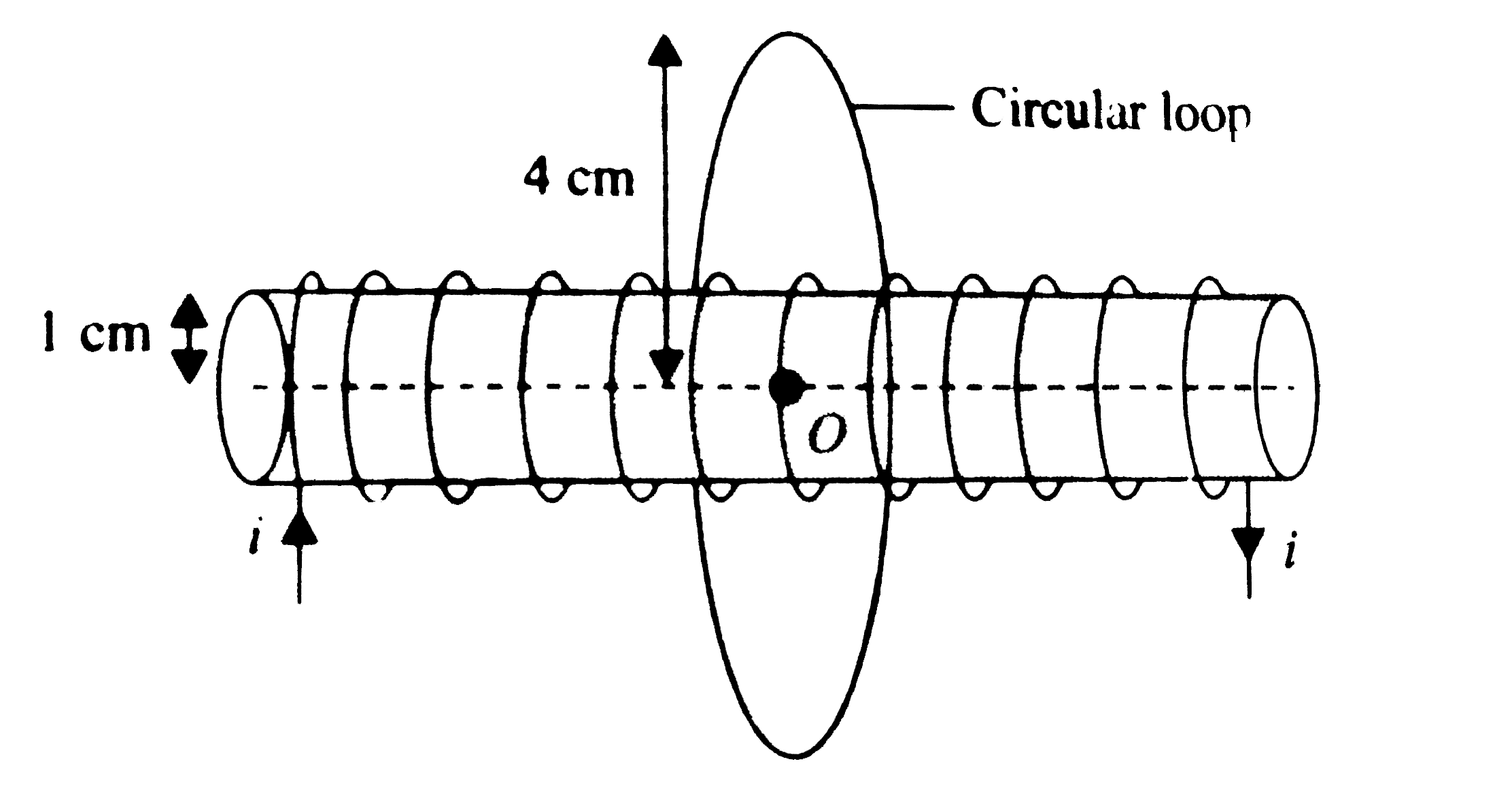
A current 't' in the solenoid results in magnetic field along its axis with magnitude `B = (mu)ni` at points well inside the solenoid on its axis. We can neglect the insignificant field outside the solenoid. This results in a magnetic flux `(phi)_(B)` through the circular loop. If the current in the winding of solenoid is changed, it will also change the magnetic field `B = (mu)_(0)ni` and hence also the magnetic flux through the circular loop. Obvisouly, it will result in an induced emf or induced electric field in the circular loop and an induced current will appear in the loop. Let current in the winding of solenoid be reduced at a rate of `75 A //sec`.
Magentic flux through the loop due to external magnetic field will be
I is the current in the loop
`a_(1)` is the radius of solendoid and `a_(1)=1cm` (given)
`a_(2)` is the radius of circular loop and `a_(2)=4cm` (given)
i is hte current in the solenoid
View SolutionA long solenoid having n = 200 turns per metre has a circular cross-section of radius `a_(1) = 1 cm`. A circular conducting loop of radius `a_(2) = 4 cm` and resistance ` R = 5 (Omega)` encircles the solenoid such that the centre of circular loop coincides with the midpoint of the axial line of the solenoid and they have the same axis as shown in Fig.
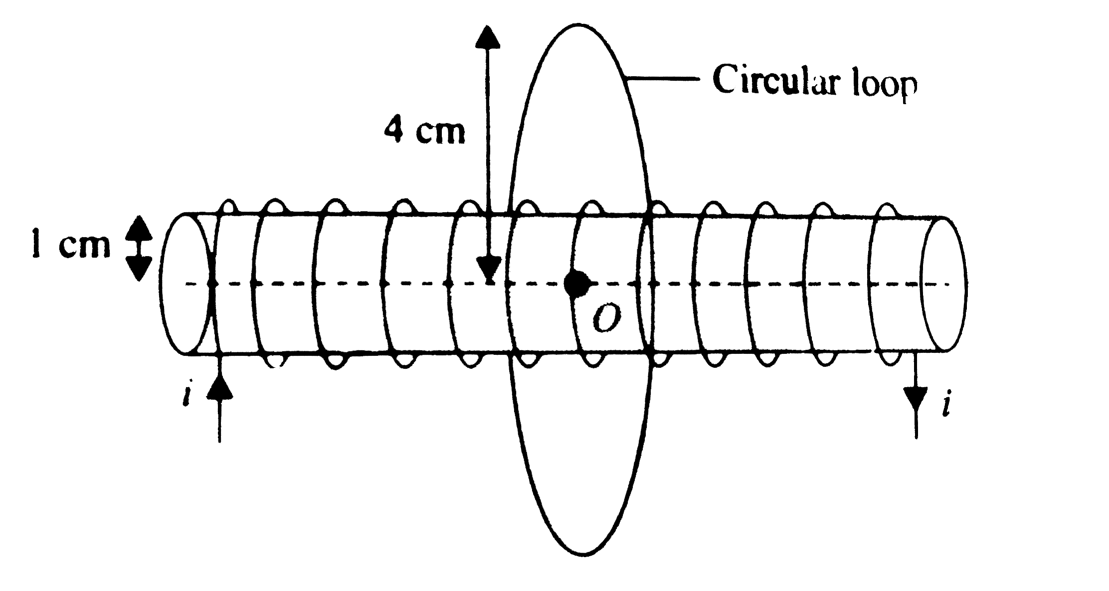
A current 't' in the solenoid results in magnetic field along its axis with magnitude `B = (mu)ni` at points well inside the solenoid on its axis. We can neglect the insignificant field outside the solenoid. This results in a magnetic flux `(phi)_(B)` through the circular loop. If the current in the winding of solenoid is changed, it will also change the magnetic field `B = (mu)_(0)ni` and hence also the magnetic flux through the circular loop. Obvisouly, it will result in an induced emf or induced electric field in the circular loop and an induced current will appear in the loop. Let current in the winding of solenoid be reduced at a rate of `75 A //sec`.
When the current in the solenoid becomes zero so that external magnetic field for the loop stops changing, current in the loop will follow a differenctial equation given by [You may use an approximation that field at all points in the area of loop is the same as at the centre
View SolutionThe potential difference across a 2-H inductor as a function of time is shown in Fig. At time `t = 0`, current is zero.
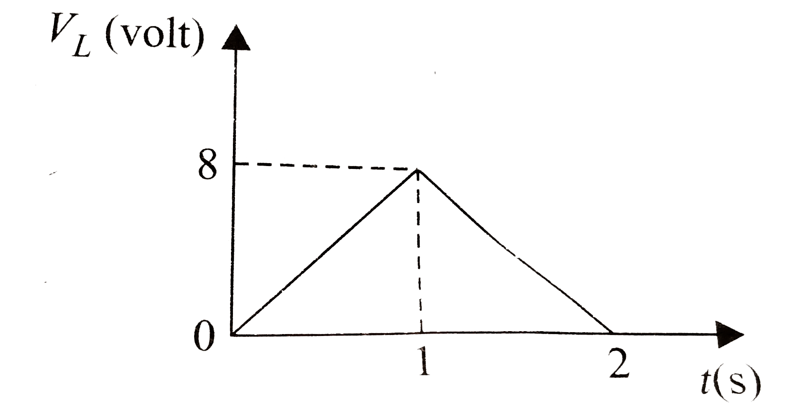
Area under `V_(L) - t` graph gives
View SolutionThe potential difference across a 2-H inductor as a function of time is shown in Fig. At time t = 0, current is zero.
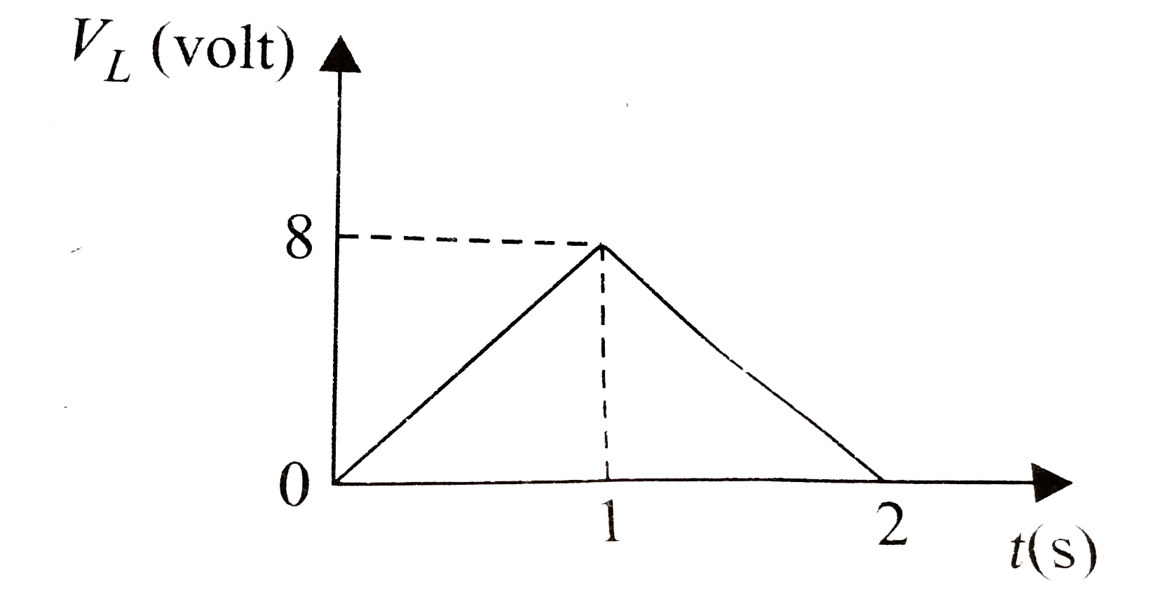
Current at t = 1 s is
View SolutionThe potential difference across a 2-H inductor as a function of time is shown in Fig. At time t = 0, current is zero.
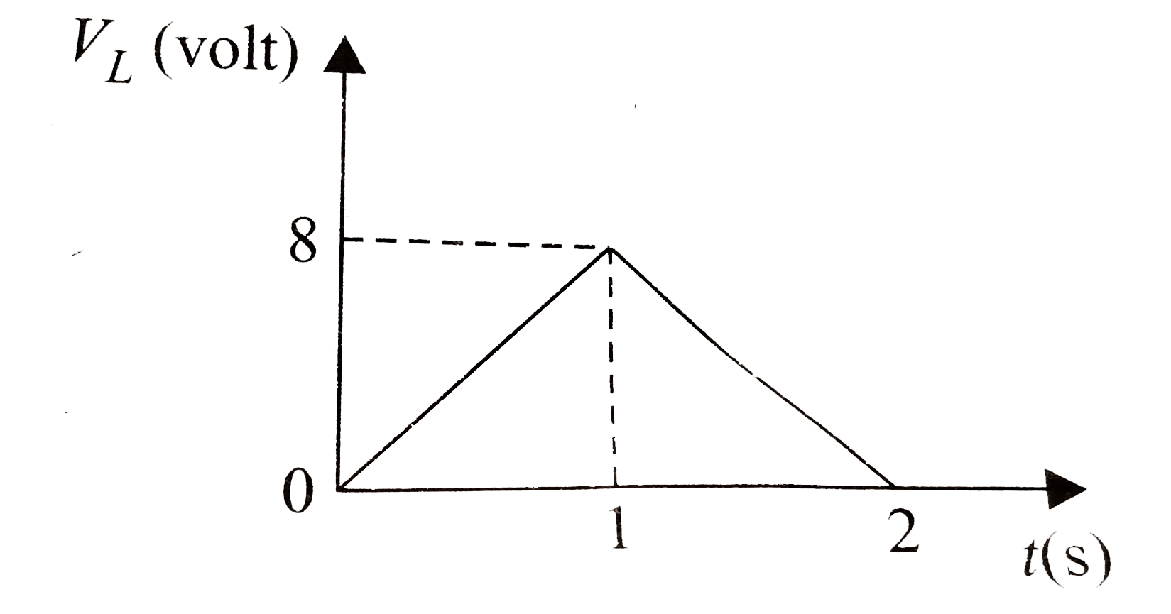
The variation of current versus time is
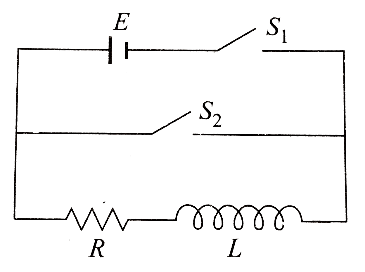
View SolutionConsider the circuit shown below. When switch `S_(1)` is closed, let I be the current at time t, then applying Kirchhoff's law
`E-iR-L (di)/(dt) = 0 or int_(0)^(i) (di)/(E-iR) = 1/L int_(0)^(1) dt`
`i=E/R (1-e^(-R/l *t))`
`L/R` = time constant of circuit
When current reaches its steady value `(=i_(0)`, open `S_(1)` and close `S_(2)`, the current does reach to zero finally but decays expnentially. The decay equation is given as `i=i_(0)e^(-R/L *T)`).
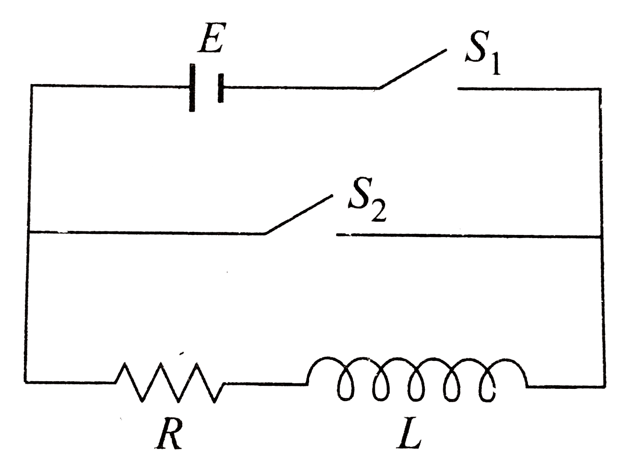
When a coil carrying a steady current is short circuited, the current decreases in it `eta` times in time `t_(0)`. The time constant of the circuit is
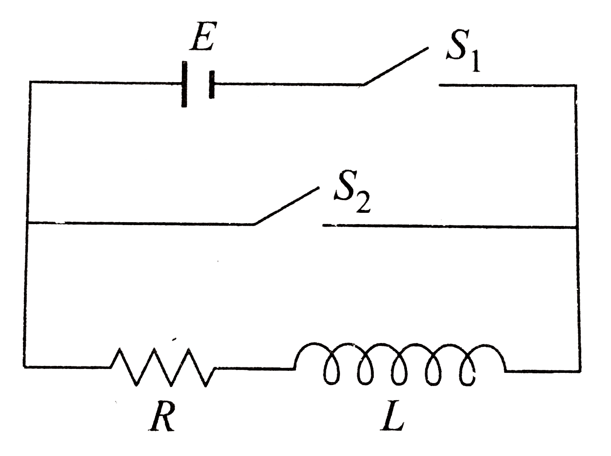
View SolutionConsider the circuit shown below. When switch `S_(1)` is closed, let I be the current at time t, then applying Kirchhoff's law
`E-iR-L (di)/(dt) = 0 or int_(0)^(i) (di)/(E-iR) = 1/L int_(0)^(1) dt`
`i=E/R (1-e^(-R/l *t))`
`L/R` = time constant of circuit
When current reaches its steady value `(=i_(0)`, open `S_(1)` and close `S_(2)`, the current does reach to zero finally but decays expnentially. The decay equation is given as `i=i_(0)e^(-R/L *T)`.
Three idenctical rings. The first (a). slips without rolling and the second (b) rolls without slipping and the third rolls with slipping .
View SolutionConsider the circuit shown below. When switch `S_(1)` is closed, let I be the current at time t, then applying Kirchhoff's law
`E-iR-L (di)/(dt) = 0 or int_(0)^(i) (di)/(E-iR) = 1/L int_(0)^(1) dt`
`i=E/R (1-e^(-R/l *t))`
`L/R` = time constant of circuit
When current reaches its steady value `(=i_(0)`, open `S_(1)` and close `S_(2)`, the current does reach to zero finally but decays expnentially. The decay equation is given as `i=i_(0)e^(-R/L *T)`.
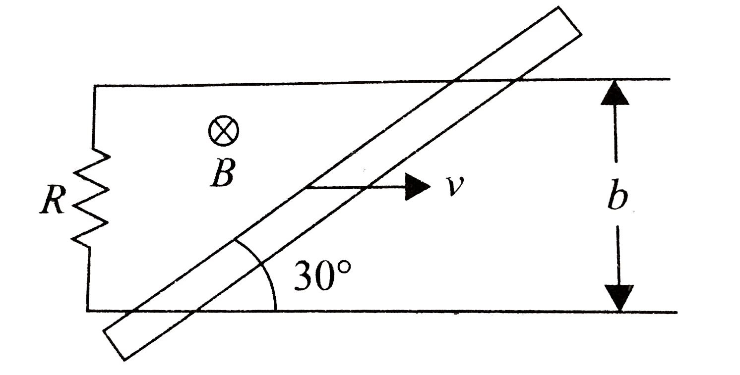
A wire is sliding as shown in fig . The angle between the acceleration and velocity of the wire is
View SolutionTwo long parallel conducting horizontal rails are connected by a conducting wire at one end. A uniform magnetic field B (directed vertically downwards) exists in the region of space.
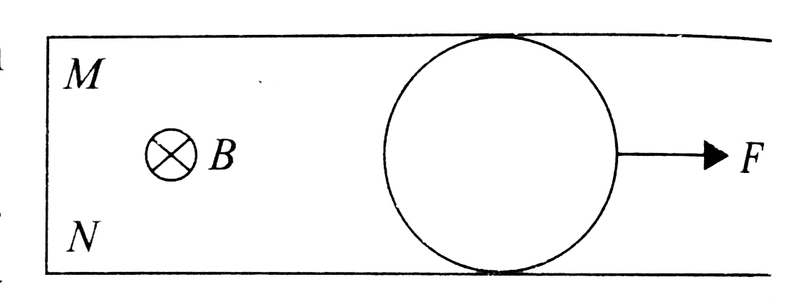
A light uniform ring of diameter d which is practically equal to separation between the rails is placed over the rails as shown in Fig. If resistance of ring be `(lambda)` per unit length
The current in the wire MN is
View SolutionTwo long parallel conducting horizontal rails are connected by a conducting wire at one end. A uniform magnetic field B (directed vertically downwards) exists in the region of space.
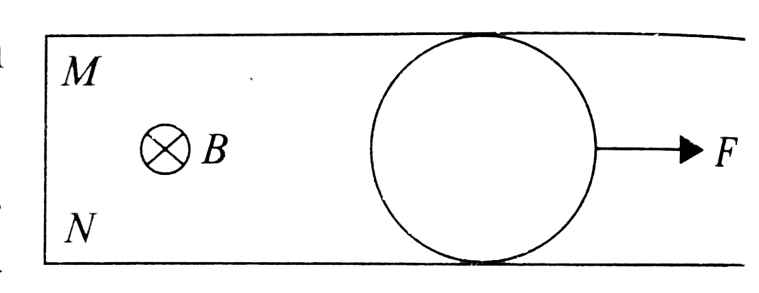
A light uniform ring of diameter d which is practically equal to separation between the rails is placed over the rails as shown in Fig. If resistance of ring be `(lambda)` per unit length
The force required to pull the ring with uniform velocity v is
View SolutionA uniform conducting ring of mass `pi` kg and radius 1 m is kept on smooth horizontal table. A uniform but time varying magnetic field `B = (hat (i) + t^(2) hat (j))T` is present in the region, where t is time in seconds. Resistance of ring is `2 (Omega)`. Then
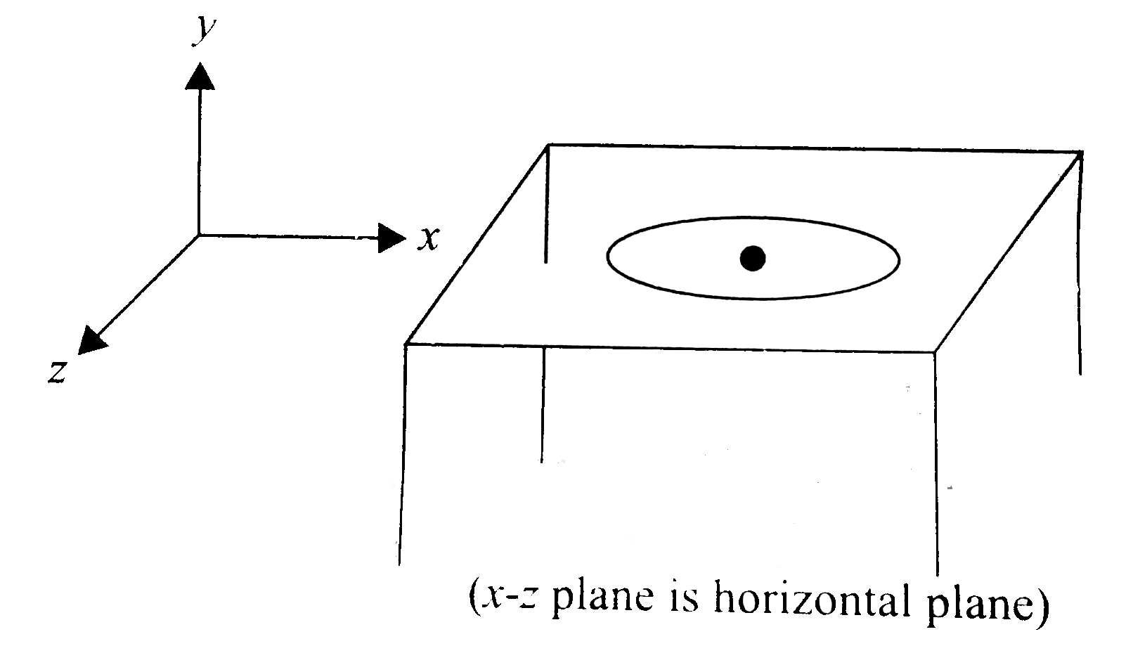
Net magnetic field (in Newton) on conducting ring as function of time is
View SolutionA uniform conducting ring of mass `pi` kg and radius 1 m is kept on smooth horizontal table. A uniform but time varying magnetic field `B = (hat (i) + t^(2) hat (j))T` is present in the region, where t is time in seconds. Resistance of ring is `2 (Omega)`. Then
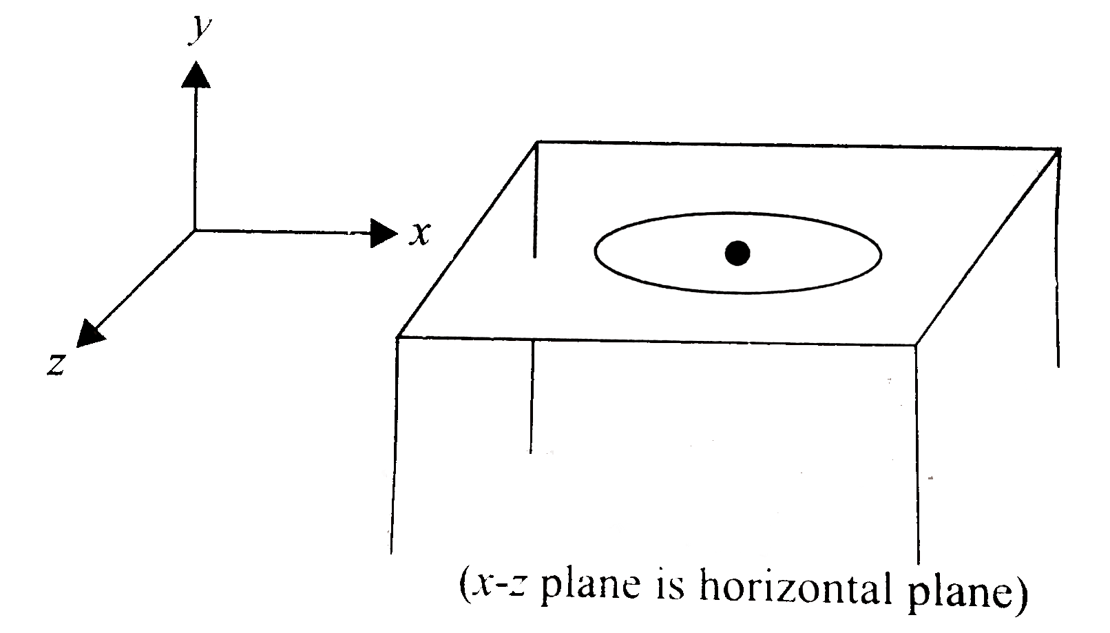
Time (in second) at which ring start toppling is
View SolutionA uniform conducting ring of mass `pi` kg and radius 1 m is kept on smooth horizontal table. A uniform but time varying magnetic field `B = (hat (i) + t^(2) hat (j))T` is present in the region, where t is time in seconds. Resistance of ring is `2 (Omega)`. Then
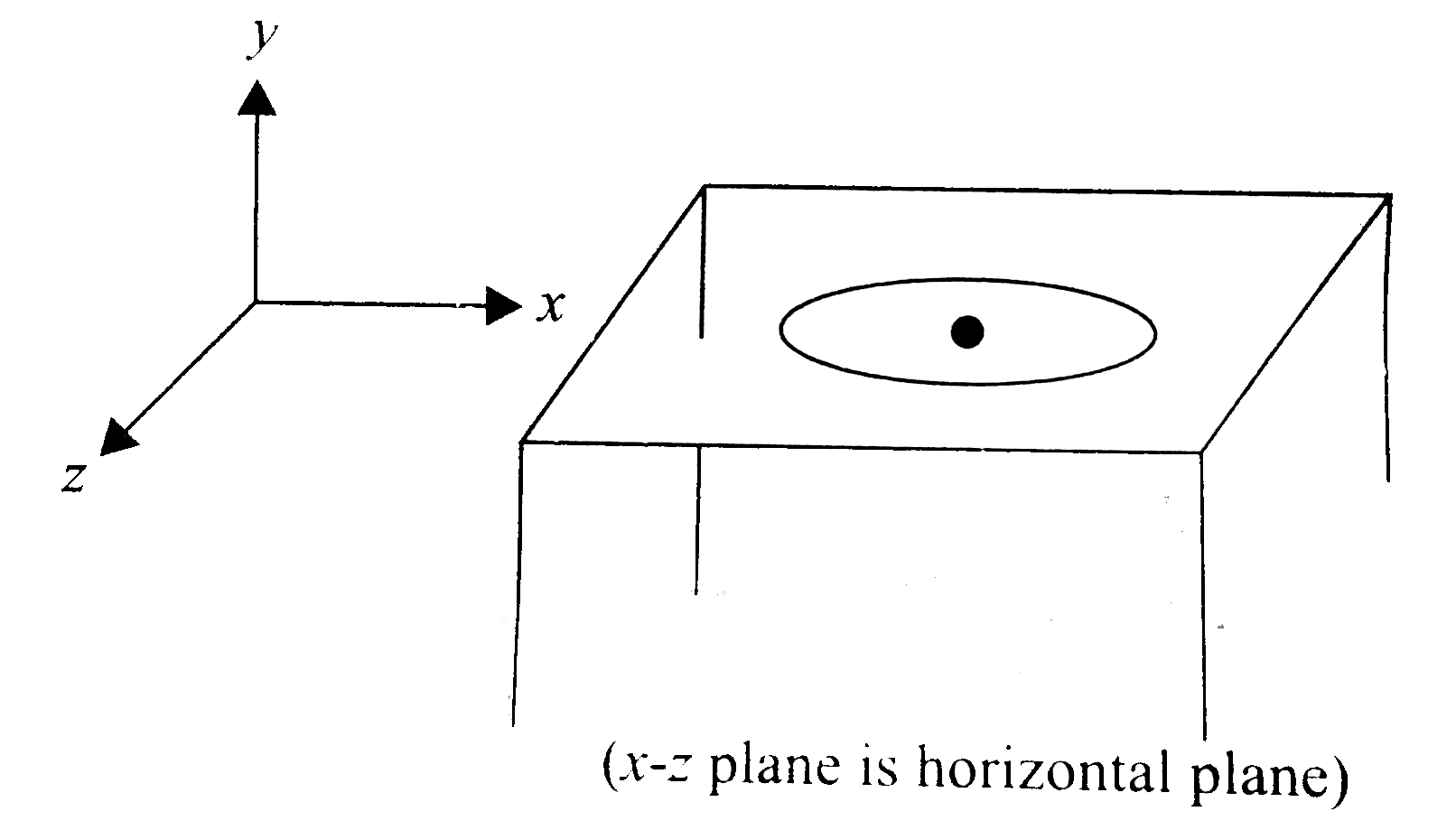
Heat generated (in kJ) through the ring till the instant when ring start toppling is
View SolutionA uniform conducting ring of mass `pi` kg and radius 1 m is kept on smooth horizontal table. A uniform but time varying magnetic field `B = (hat (i) + t^(2) hat (j))T` is present in the region, where t is time in seconds. Resistance of ring is `2 (Omega)`. Then
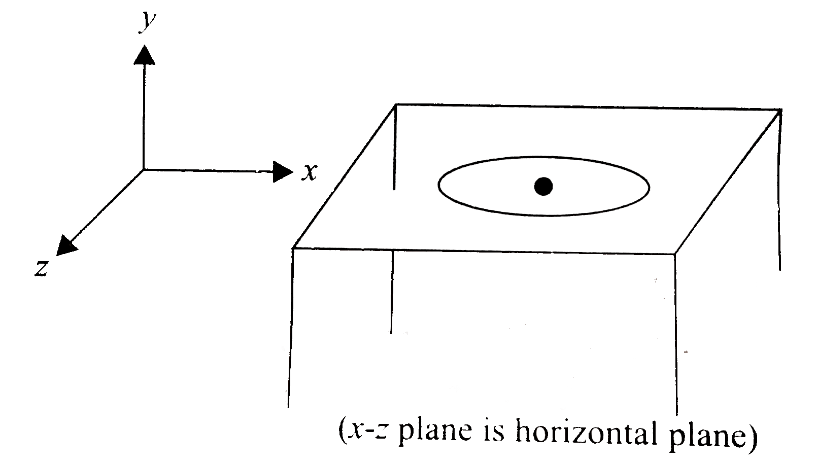
Induced electric field (in volt/meter) at the circumference of ring at the instant ring start toppling is
View Solution
Linked Comprehension questions and complete solutions for chapter MISCELLANEOUS VOLUME 5 of CENGAGE PHYSICS (HINGLISH) of Class 12