Complete Solutions to MULTIPLE CHOICE QUESTIONS LEVEL-II of chapter E.M. INDUCTION AND A.C. CURRENTS of Class 12 book with complete answers and questions
| Class 12 | PHYSICS |
| Chapter | E.M. INDUCTION AND A.C. CURRENTS |
| MODERN PUBLICATION | MULTIPLE CHOICE QUESTIONS LEVEL-II |
| Number Of Questions | 51 |
| Academic Year | 2023-24 |
A copper rod of length l is rotated about the end perpendicular to a uniform magnetic field B with:
View SolutionA small square loop of wire of side l is placed outside a large (square loop) of side L. `(L gt gt l)` The loops are coplanar and their centres coincide. The mutual induction of the system is:
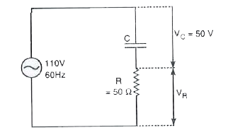
View SolutionIn the given circuit `V_c=50V and R=50 Omega`. The values of C and `V_R` are:
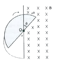
View SolutionA semi-circular wire loop of radius a has its centre at the boundary of a uniform magnetic field B. At the instant t=0, its diameter is along the boundary of the field and starts rotating in the clockwise direction with angular acceleration a. Find the emf induced in the loop as a function of time t.
View SolutionA superconducting ring of radius a and inductance L is located in a uniform magnetic field of induction B. the plane of ring is parallel to B and the current in the ring is zero. Then the ring is turned through `90^@` so that plane is perpendicular to the field. What is the work done in turning the ring?
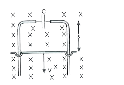
View SolutionA conductor of length l and mass m can slide without friction along the two vertical conductors connected at the top through a capacitor. A uniform magnetic field B is set up `bot` to plane of paper. Find the voltage across the capacitor in terms of distance x through which it falls.
View SolutionA power transformer is used to set up an alternating emf of 220V to 4.4kV to transmit 6.6kW of power. The primary coils has 1000 turns. What is current rating of secondary? Assume efficiency is 100%
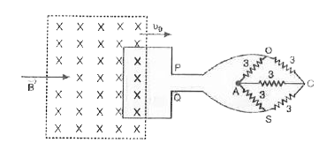
View SolutionA square metal wire loop of side 10cm and resistance `1 Omega` is moved with a constant velocity `v_0` in a uniform magnetic field of induction `B=2 Wb m^-2` as shown in fig. The magnetic field lines are `bot` to the plane of the loop . The loop is connected to network of resistors each of value `3Omega`. What should be speed of the loop so as to have a steady current of 1mA in the loop?
View SolutionA small town with a demand of 800 kW of electric power at 220V is situated 15km away from an electric plant generating power at 440V. The resistance of the two lines wires carrying power is `0.5 Omega per km`. The town gets power from the line 4000-220V step down transformer at a sub-station in the town. The line power losses in the form of heat are:
View SolutionIn Q.111 how much power the plant must supply?
View SolutionAgain in Q.112 step up transformer at the plane is characterised by:
View SolutionThe approximate formula expressing the mutual inductance of two thin co-axial loops of the same radius a when their centres are separated by a distance l, with `l gt gt a` is:
View SolutionA 22cm long solenoid having total number of turns 1000 consists of a core of cross sectional area `4 cm^2` Half portion of the core consists of air and other half is made of iron of relative permeability 500.Calculate the self inductance of the solenoid.
View SolutionA thin ring of a radius 10 cm carries a uniformly distributed charge. The ring rotates at constant speed of 1200 r.p.m about its axis `bot` to plane. Find the charge on ring if `B=3.14 times 10^-9 T`at centre.
View SolutionA 220V,50Hz a.c generator is connected to an inductor and a `50 Omega` resistance in series. The current in the circuit is 1.0A What is P.D. across inductor?
View SolutionA `8 mu F` capacitor is connected across 220V, 50 Hz line . What is peak value of charge through capacitor?
View SolutionIn an a.c. circuit the resistance `R=0.2 Omega` At a certain instant `V_A-V_B=0.5V, I=0.5A , (DeltaI)/(Delta t)=8A//s` The inductance of coil is

View SolutionIn LR circuit, the current increases to `3/4 th` of its max. value in 4s, then time constant of circuit is:
View SolutionA coil has a inductance of 0.7H and is joined in series with a resistance of `220 Omega` When the Ac emf of 220V is applied to it, find the wattless component of current in the circuit?
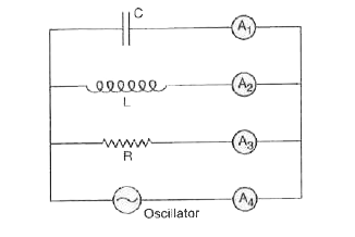
View SolutionIn the circuit shown in fig. When the frequency of oscillator is increased, the reading of ammeter `A_4` is same as that of ammeter:
View SolutionThe capacity of a capacitor which must be placed in series with a resistance of `50 Omega` and an inductance of 0.5H to bring the current in phase with voltage is
View SolutionAn alterating emf of 200V and 50 cycles is connected to a circuit of resistance of `3.142 Omega` and inductance 0.01 H The lag in a time between the emf and the current is:
View SolutionA generator produces 22 kW of power at 100A at 220V. The length of the transmission line is 100 km whose resistance is 1ohm. The line loss will be:
View SolutionIn LCR current resonant frequency is 600 Hz and half power points are at 650 and 550 Hz. The quality factor is:
View SolutionIn R-L circuit the time lag between the voltage maximum and current maximum is
View SolutionKamla peddles a stationary bicycles the pedals of the bicycle are attached to a 100 turns coils of area `0.10 m^2` The coil rotates at half a revolution per second and it is placed in uniform magnetic field of 0.01 T perpendicular to the axis of rotation of the coil. What is the maximum voltage generated in the coil?
View SolutionIf the instantaneous current in a circuit is given by `i=2 cos (omega t- phi)` ampere, the r.m.s value of the current is:
View SolutionIn a region of uniform magnetic induction `B=10^-2` tesla, a circular coil of radius 30 cm and resistance `pi^2` ohm is rotated about an axis which is perpendicular to the direction of B and which forms a diameter of the coil. IF the coil rotates at 200 r.p.m the amplitude of the alternating current induced in the coil is:
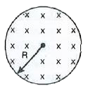
View SolutionA cylindrical space of radius R is filled with a uniform magnetic induction B parallel to the axis of the cylinder. IF B changes at a constant rate , the graph showing the variation of induced electric field with distance r from the axis of cylinder is:
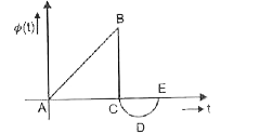
View SolutionThe graph shown the variation in magnetic flux `phi (t)` with time through a coil. Which of the statement gives below is not correct
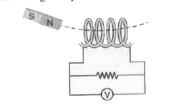
View SolutionA magnet is made to oscillate with a particular frequency passing through a coil as shown in figure. The time variation of the magnitude of emf generated across the coil during one cycle is:
View SolutionA metallic ring is dropped down, keeping its plane perpendicular to a constant and horizontal magnetic field. The ring enters the region of magnetic field at t=0 and completely emerges out at t=T sec. The current in the ring varies as:
View SolutionA wire is bent to form the double loop shown in figure. There is a uniform magnetic field direction into the plane of the loop. IF the magnetic of this field is decreasing current will flow from:
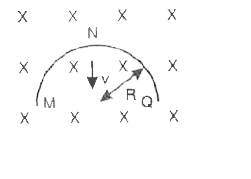
View SolutionA thin semicircular conducting ring of radius R is falling with its plane vertical in a horizontal magnetic induction `vec B`. At the position MNQ, the speed of the ring is v, the potential difference developed across the ring is:
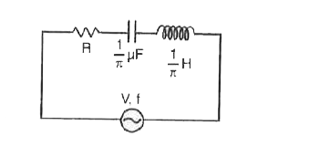
View SolutionIn the A.C. circuit shown below the supply voltage has a constant r.m.s value V but variable frequency f. At resonance , the circuit:
View SolutionA rigid conducting wire bent as shaped is released to fall freely in a horizontal magnetic field which is perpendicular to the plane of the conductor. IF magnetic field strength is B then the emf induced across the point A and C when it has fallen through a distance h will be
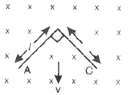
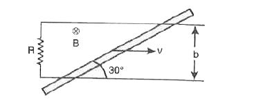
View SolutionA wire is sliding as shown in the figure. The angle between the acceleration and velocity of the wire is:
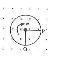
View SolutionA conducting ring of radius r is rolling without slipping with a constant angular velocity `omega`. IF the magnetic field strength in b and is directed into the page them emf induced across PQ is:
View SolutionA small circular loop of radius r is placed inside circular loop of radius `R (R gt gt r)` The loops are coplanar and their centres coincide. The mutual inductance of the system is proportional to:
View SolutionA small coil is introduced between the poles of an electromagnet so that its axis coincides with the magnetic field direction. The number of turns is n and the cross sectional area of the coil is A. When the coil turns through `180^@` about its diameter. the charge flowing through the coil is Q. The total resistance of the circuit is R. What is the magnitude of the magnetic induction?
View SolutionA wire in the form of a circular loop of radius r lies with its plane normal to a magnetic field B . IF the wire is pulled to take a square shape in the same plane in time t, the emf induced in the loop is given by:
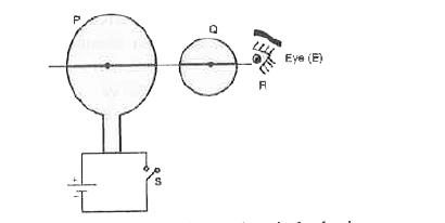
View SolutionAs shown in fig. P and Q are two coaxial conducting loops separated by some distance. When switch S is closed,a closkwise current `I_p` flows in P and an induced current `I_(Q_2)` flow in Q. the switch remains closed for a long time. When S is opened, a current `I_(Q_2)` flows in Q. Then the directions of `I_(Q_2)` and `I_(Q_2)` are
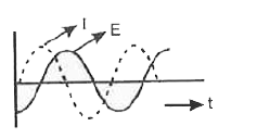
View SolutionWhen the A.C source of emf `E=E_0 sin (100t)` is connected across a circuit the phase differences between emf and current I in the circuit is observed to be `pi/4`. As shown in fig. If the circuit consists possibly only of R-C or R-L or L-C in series, what will be the the relation between the two elements of circuit?
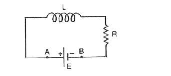
View SolutionAn inductor `(L=100mH)` a resistor `(R=100 Omega)` and a battery are initially connected in series as shown in figure. After the long time, the battery is disconnected after short circuiting the points A and B. The current it the circuit 1ms after the short circuit is:
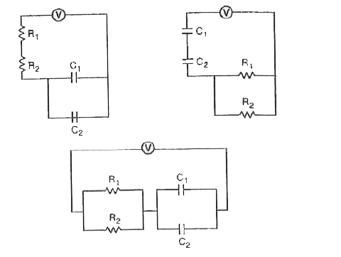
View SolutionFind the time constant for the given RC circuit in the given order respectively
`R_1=1 Omega, R_2=2 Omega, C_1=4 mu F,C_2=2 mu F`
View SolutionThe coaxial solenoids are made by winding him insulated wire over a pipe of cross sectional area `A=10 cm^2` and length =20 cm. IF one of the solenoids has 300 turns and the other 400 turns, their mutual inductance is
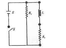
View SolutionAn inductance of inductance L=400 mH and resistors of resistance `R_1=2 Omega and R_2=2 Omega` are connected to a battery of emf 12V as shown in the figure. The internal resistance of the battery is negligible. The switch S is closed at t=0. The potential drop across L as a function of time is :
View SolutionLet C be the capacitance of a capacitor discharging through a resistor R. Suppose `t_1` is the time taken for the energy stored in the capacitor to reduce to half its initial value and `t_2` is the time taken for the charge to reduce to one-fourth its initial value. Then the ratio `t_1//t_2` will be:
View SolutionA rectangular loop has a sliding connector PQ of length I and resistance R `Omega` and it is moving with a speed v as shown.
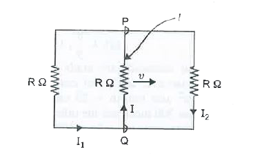
The set up is placed in a uniform magnetic field going into the plane of the paper. The three currents `I_1,I_2 and I` are:
View SolutionIn a series LCR circuit R=200 W and the voltage and the frequency of the main supply is 220V and 50Hz respectively. On taking out the capacitance from the circuit the current lags behind the voltage by `30^@` On taking out the inductor from the circuit the current leads the voltage by `30^@`. The power dissipated in the LCR circuit is:
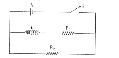
View SolutionIn the circuit shown below , the key K is closed at t=0. The current through the battery is:
View Solution
MULTIPLE CHOICE QUESTIONS LEVEL-II questions and complete solutions for chapter E.M. INDUCTION AND A.C. CURRENTS of MODERN PUBLICATION PHYSICS (KANNADA ENGLISH) of Class 12