Complete Solutions to MULTIPLE CHOICE QUESTIONS LEVEL -III (QUESTIONS FROM AIEEE/JEE EXAMINATION) of chapter E.M. INDUCTION AND A.C. CURRENTS of Class 12 book with complete answers and questions
| Class 12 | PHYSICS |
| Chapter | E.M. INDUCTION AND A.C. CURRENTS |
| MODERN PUBLICATION | MULTIPLE CHOICE QUESTIONS LEVEL -III (QUESTIONS FROM AIEEE/JEE EXAMINATION) |
| Number Of Questions | 14 |
| Academic Year | 2023-24 |
Combination of two identical capacitors, a resistor R and a dc voltage source of voltage 6V is used in an experiment on a (C-R) circuit . It is found that for a parallel combination of the capacitor the time in which the voltage to the fully charged combination reduces to half its original voltage is 10 second. For series combination the time needed for reducing the voltage of the fully charged series combination by half is:
View SolutionA horizontal straight wire 20m long expanding from east to west falling with a speed of `5.0 ms^-1` at right angles to the horizontal component of the earth's magnetic field `0.30 times 10^-4 Wb//m^2` The instantneous value of the emf induced of the wire will be:
View SolutionA fully charged capacitor C with initial charge `q_0` is connected to a coil of self inductance L at t=0. The time at which the energy is stored equality between the electric and the magnetic field is:
View SolutionA resistor R and `2muF` capacitor in series is connected through a switch to 200V direct supply . Across the capacitor is a neon bulb that lights up at 120V. Calculate the value of R to make the bulb light up 5s after the switch has been closed.
View SolutionA series R-C circuit is connected to A.C voltage source. Consider two cases(A) when C is without a dielectric medium and (B) when C is filled with dielectric constant 4. The current `I_R` through the resistor and voltage `V_c` across the capacitor are compared in the two cases which of the following is/are true?
View SolutionA series R-C combination is connected to an AC voltage of angular frequency `omega=500 radian//s`. If the impedance of the R-C circuit is `Rsqrt1.25`, the time constant of the circuit is
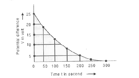
View SolutionThe figure shows an experimental plot for discharging of a capacitor in an R-C circuit . The time constant t of the circuit lies between:
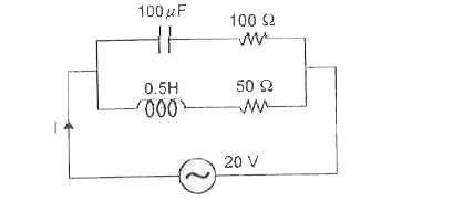
View SolutionIn the given circuit the AC source has `omega=100 rad//s` Considering the inductor and capacitor to be ideal, the correct choice is
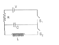
View SolutionIn an LCR circuit as shown below both switches are open initially. Now switch `S_1` is closed, `S_2` kept open. Which of the following statement is correct?
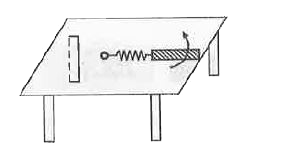
View SolutionA metallic rod of length l is tied to a string of length 2l and made to rotate with angular speed `omega` on a horizontal table with one end of the string fixed. IF there is a vertical magnetic field B in the region the emf induced across the ends of the rod is:
View SolutionA circular loop of radius 0.3 cm lies parallel to a much bigger circular loop of radius 20 cm. The centre of the small loop is on the axis of the bigger loop. The distance between their centres is 15 cm. IF a current of 2.0A flows through the smaller loop, then the flux linked with bigger loop is:
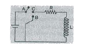
View SolutionIn the circuit shown here, the point C is kept connected to point A till the current flowing through the circuit becomes constant. Afterwards, suddenly point C is disconnected from point A and connected to point B at time t=0 Ratio of the voltage across resistance and the inductor at `t=L//R` will be equal to:
View SolutionAn LCR circuit is equivalent to a damped pendulum. In an LCR circuit the capacitor is charged to `Q_0 and ` then connected to the L and R as shown below:
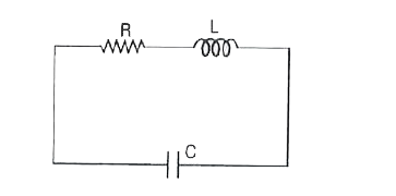
IF a students plots graphs of the square of maximum charge on the capacitor with time (t) for two different values `L_1 and L_2 (L_1 gt L_2)` then which of the following represents this graph correctly?
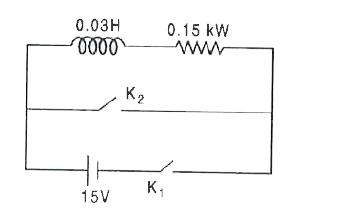
View SolutionAn inductor and a resistor are connected in series to a battery of 15V EMF in a circuit shown below. The key `K_1` has been kept closed for a long time Then at t=0 `K_1` is opened and key `K_2` is closed simultaneously At t=1 ms, the current in the in the circuit will be:
View Solution
MULTIPLE CHOICE QUESTIONS LEVEL -III (QUESTIONS FROM AIEEE/JEE EXAMINATION) questions and complete solutions for chapter E.M. INDUCTION AND A.C. CURRENTS of MODERN PUBLICATION PHYSICS (KANNADA ENGLISH) of Class 12