Complete Solutions to Level-VI of chapter CAPACITANCE of Class 12 book with complete answers and questions
| Class 12 | PHYSICS |
| Chapter | CAPACITANCE |
| NARAYANA | Level-VI |
| Number Of Questions | 28 |
| Academic Year | 2023-24 |
Seven capacitors each of capacitance `2muF` are to be connected in a configuration to obtain an effective capacitance of `(10/11)muF`. Which of the combination (s) shown in figure will achieve the desired result?
View SolutionA parallel plate capacitor of capacitance C is connected to a battery and is charged to a potential difference V. Another capacitor of capacitance 2C is ismilarly charged to a potential difference 2V. The charging battery is now disconnected and the capacitors are connected in parallel to each other in such a way that the poistive terminal of one is connected to the negative terminal of the other. The final energy of the configuration is
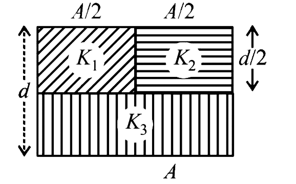
View SolutionA parallel plate capacitor of area A, plate separation d and capacitance C is filled with three different dielectric materials having dielectric constants `k_1`, `k_2` and `k_3` as shown. If a isngle dielectric material is to be used to have the same capacitance C in this capacitor, then its dielectic constant k is given by
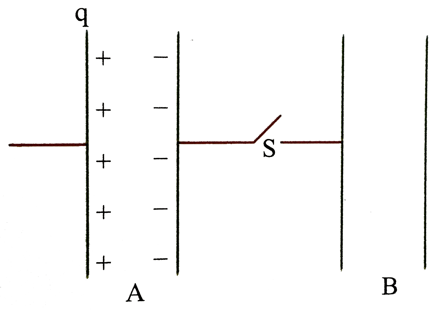
View SolutionConsider the situation shown in the figure. The capacitor `A` has a charge `q` on it whereas `B` is uncharged. The charge appearing on the capacitor `B` a long `7` time after the switch is closed is :
 .
.
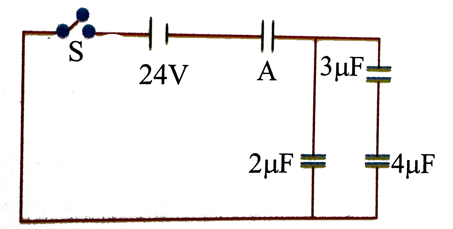
View SolutionFour capacitor and a battery of `emf 24 V` are connected as shown in the figure. Initially, `S` is open and the capacitors are uncharged. After `S` is closed and steady state is attained, the potential difference across the `4 mu f` capacitor is `7.5 V`. The capacitance in `mu f` of the capacitor `A` is.
 .
.
View SolutionTwo identical capacitors, have the same capacitance C. One of them is charged to potential `V_1` and the other `V_2`. The negative ends of the capacitors are connected together. When the poistive ends are also connected, the decrease in energy of the combined system is
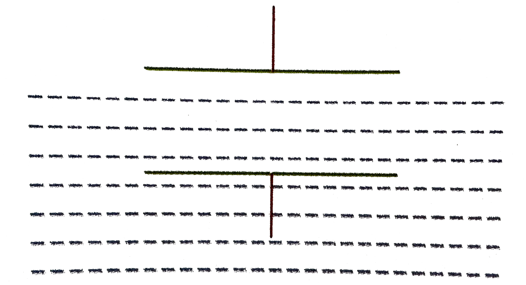
View SolutionA parallel plate capacitor is located horizontally, so that one of its plates is submerged into liquid while the other is over the surface. The dielectric constant of the liquid is equal to `k`. Its density is equal to `rho`. To what height will the level of the liquid in the capacitor rise after its plates gets a charge of surface density `sigma` ?
 .
.
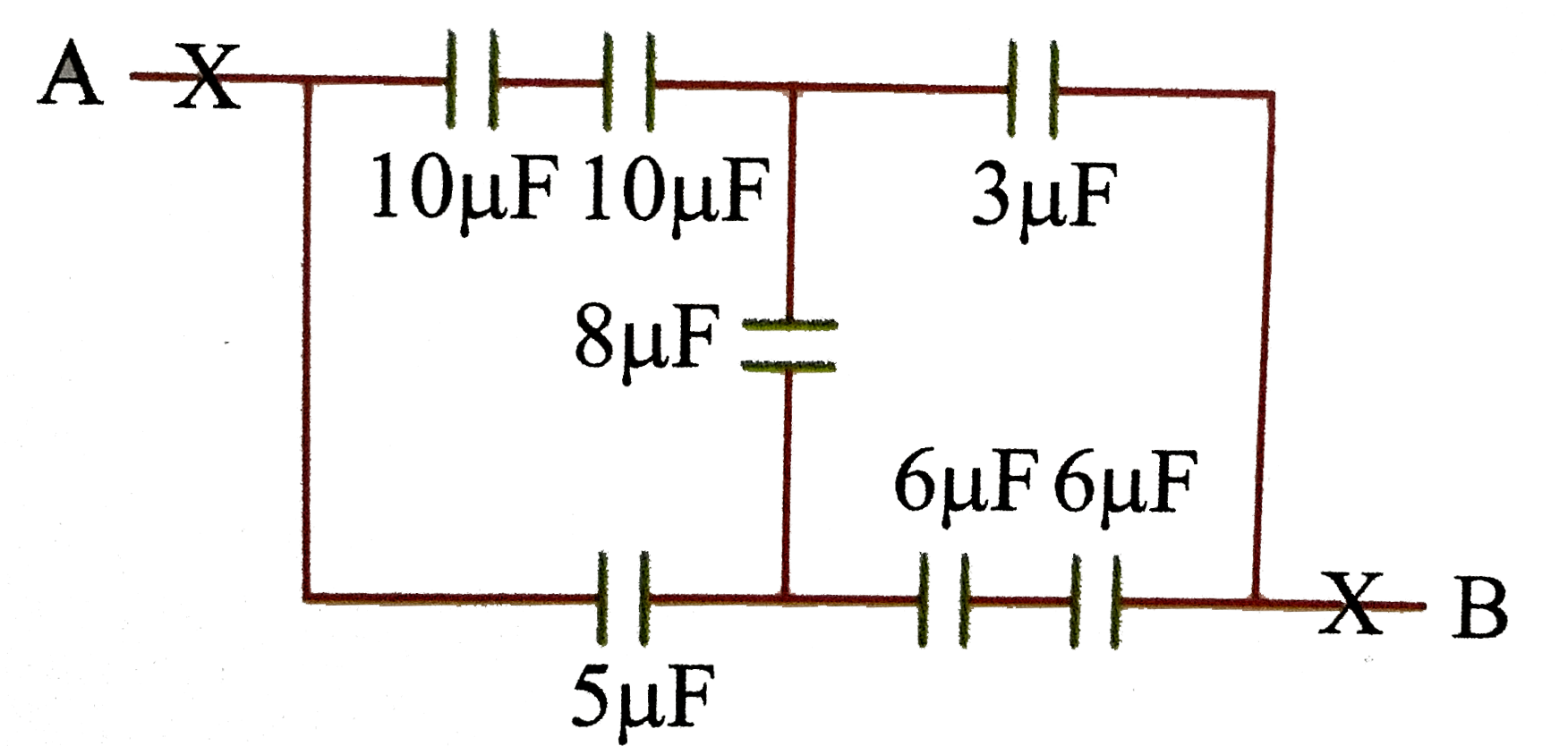
View SolutionSeven capacitor are connected as shown in the figure.
 .
.
The equivalent capacitance in `muF` between `A` and `B` is.
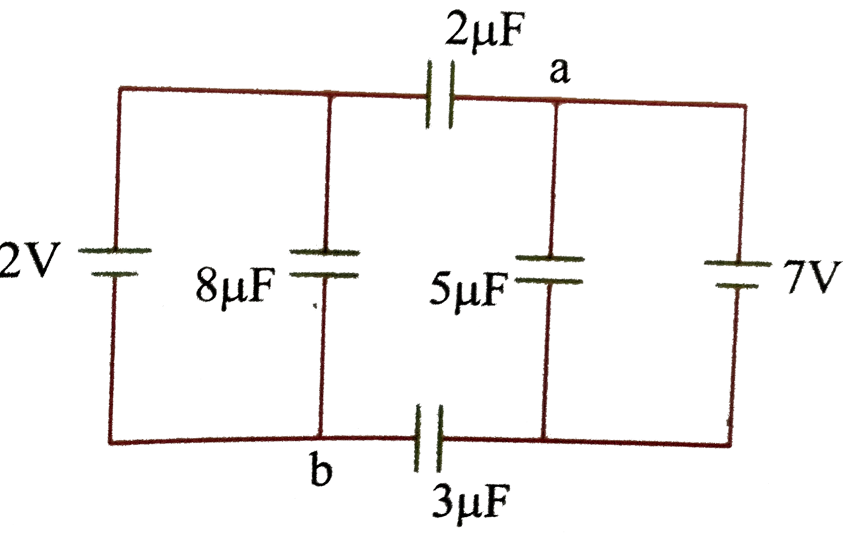
View SolutionFour capacitors and two batteries are connected as shown in the diagram. The `p.d` between the points `a` and `b` is
 .
.
View SolutionA parallel plate air capacitor is connected to a battery. The quantities charge, voltage, electric field and energy associated with this capacitor are given by `Q_0` , `V_0`, `E_0` and `U_0` respectively. A dielectric slab is now introduced to fill the space between the plates with battery still in connection. The corresponding quantities now given by Q, V, E and U are related to the previous one as
View SolutionA parallel plate capacitor is charged and the charging battery is then disconnected. If the plates of the capacitor are moved farther apart by means of insulating handles:
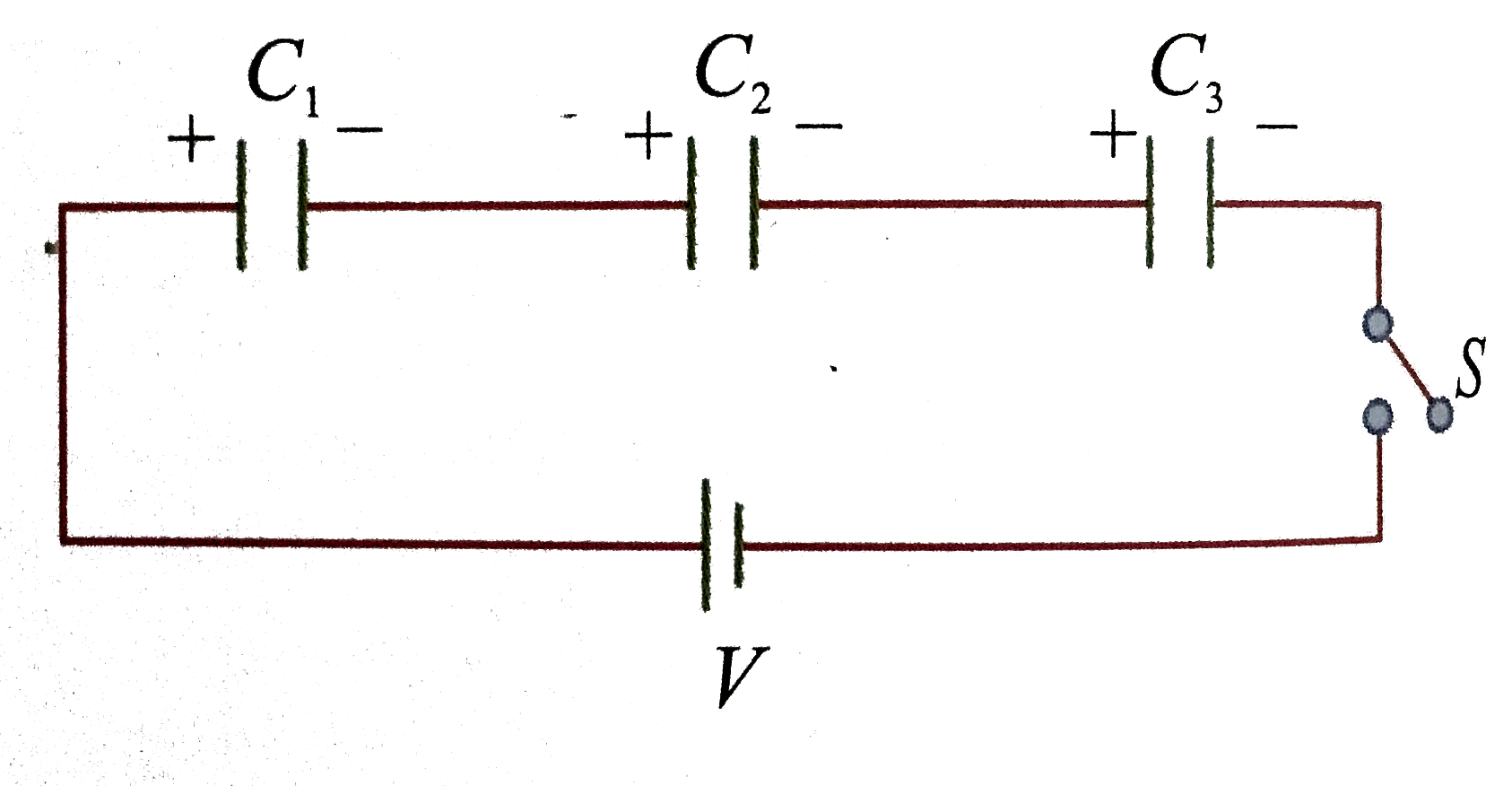
View SolutionThree parallel plate capacitors `C_(1) = 4 muF,C_(2) =2mu F,C_(3) = 6muF` with respective charges `q_(1) = 20 muC,q_(2) = 10 mu C,q_(3) =5 muC` are connected in series with a battery of `emf 10 V` through an open switch as shown. Now the switch is closed and steady state is reached.
 .
.
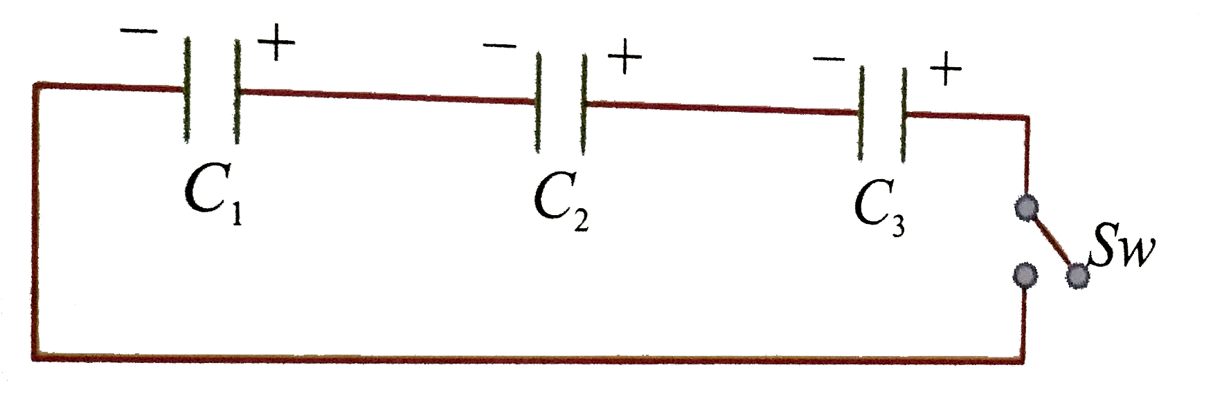
View SolutionThree parallel plate capacitors `C_(1) = 4 muF,C_(2) =2mu F,C_(3) = 6muF` with respective charges `q_(1) = 20 muC,q_(2) = 10 mu C,q_(3) =5 muC` are connected in series with a battery of `emf 10 V` through an open switch as shown. Now the switch is closed and steady state is reached.
 .
.
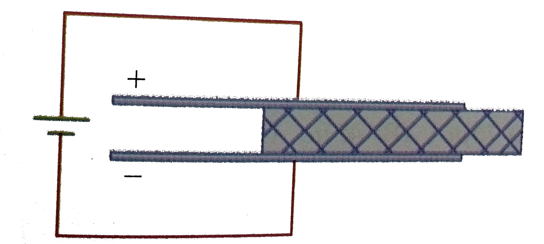
View SolutionA parallel plate capacitor has smooth square plates of side ''a''. It is connected to battery of `emf .V.` Now a smooth dielectric slab of length a which can fill the space between the plates is introduced between the plates from one side as shown in the figure. Now
 .
.
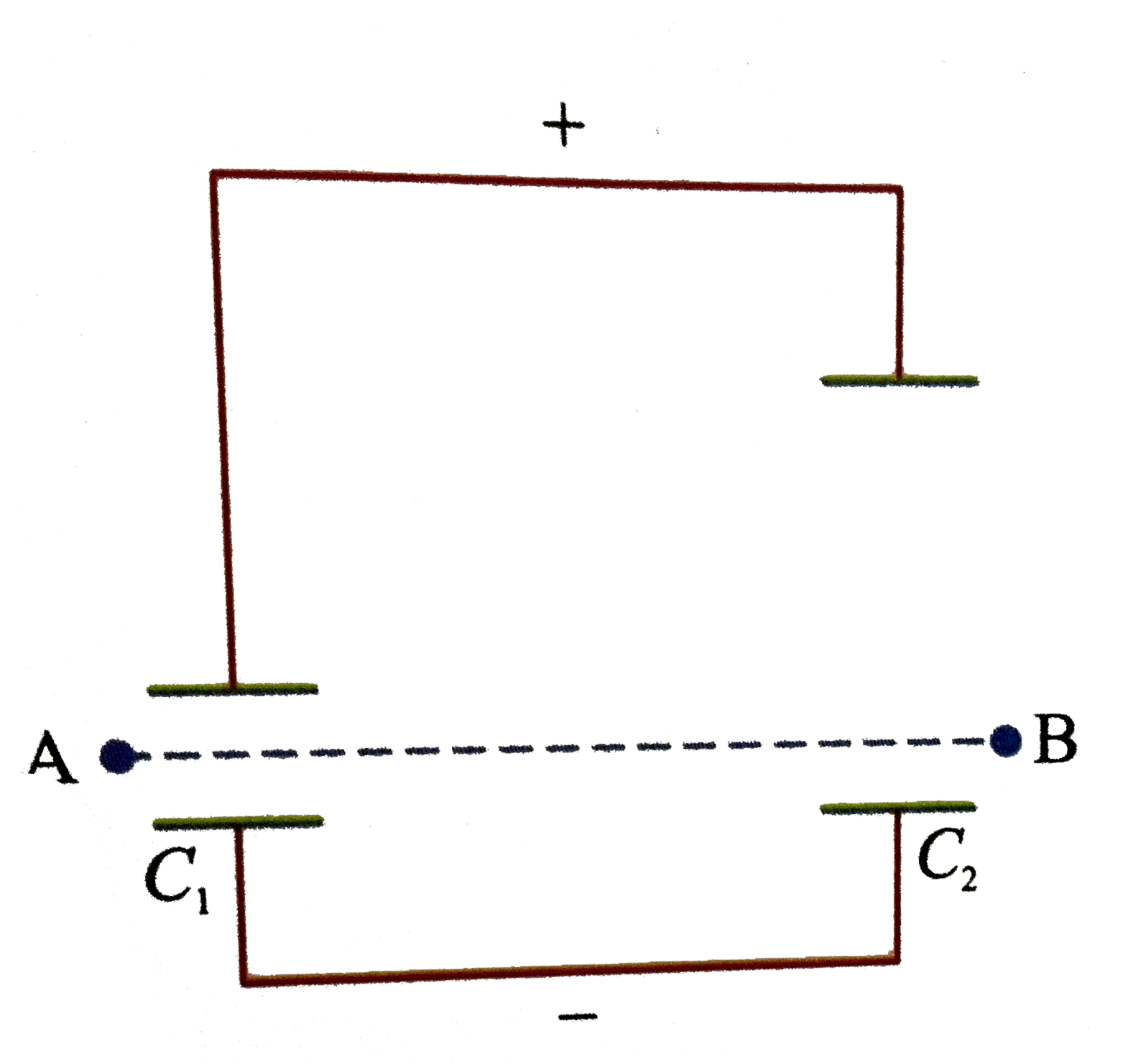
View SolutionTwo parallel-plate capacitors with different distances between the plates are connected in parallel to a voltage source. A point positive charge is moved from a point `A`, that is exactly in the middle between the plates of a capacitor `C_(1)` to a point `B`(or a capacitor `C_(2)` that lies at a distance from the negative plate of `C_(2)` equal to half the distance between the plates of `C_(1)`) During this process of moving the charge.
 .
.
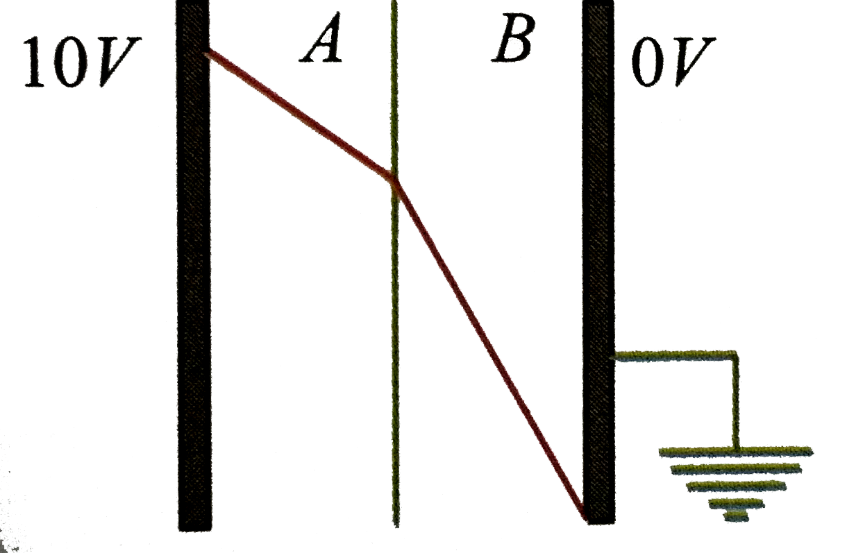
View SolutionA parallel-plate capacitor is filled with a dielectric upto one-half of the distance between the plates. The manner in which, the potential between the plates varies is illustrated in the figure
 .
.
View SolutionA capacitor of capacitance `2 mu F` is initially connected to a battery of emf `10` volt and steady state is reached. Now, `10 V` battery is removed and another battery of emf `20 V` is connected with like polarities together. Find the amount of heat energy developed (after the steady state is reached).
View SolutionSolve the above problem, if `20 V` battery is connected with unlike polarities together.
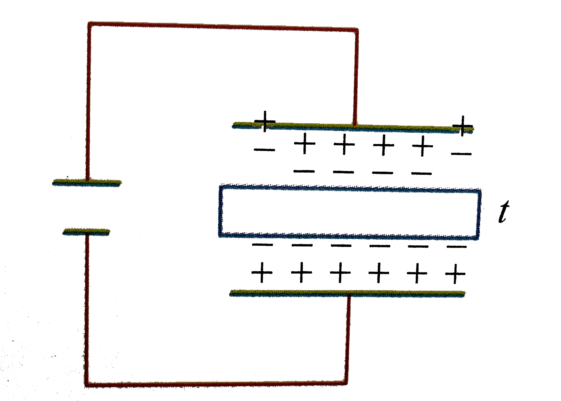
View SolutionA conducting slab is in between a parallel plate capacitor. The thickness of the slab is `t`. The distance between the plates is `d(d gt t)`. A battery of emf 'v' volt is connected across the plates (see diagram). The system attains steady state. Now select the correct options.
 .
.
View SolutionIn the circuit shown in the figure four capacitors are connected to a battery. The `p.d` across the `7 mu F` capacitor is `6V`.
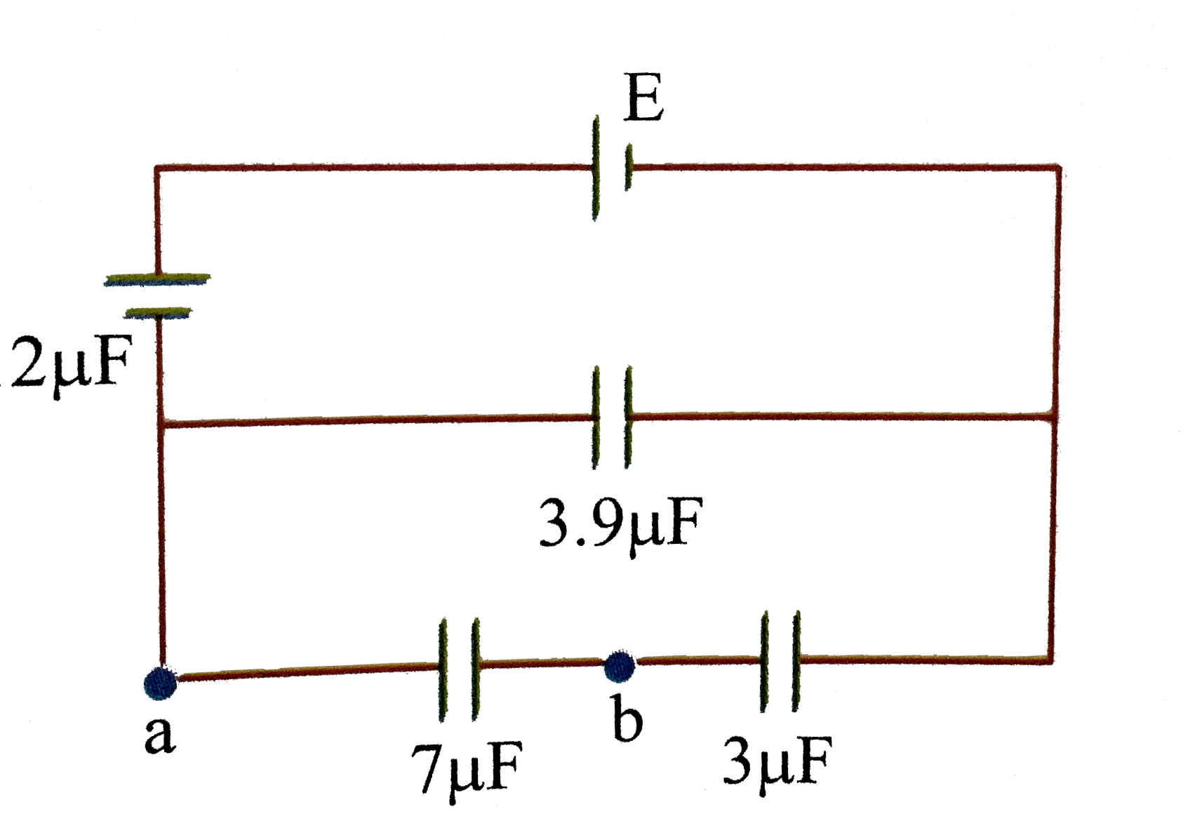 .
.
View SolutionIn the circuit diagram shown here seven capacitors are connected to a source of emf `E`. Initially, the switch `S` is closed and steady state attained. Now, the potential difference between the points 'a' and 'b' is `4` volt. Now, answer the following :
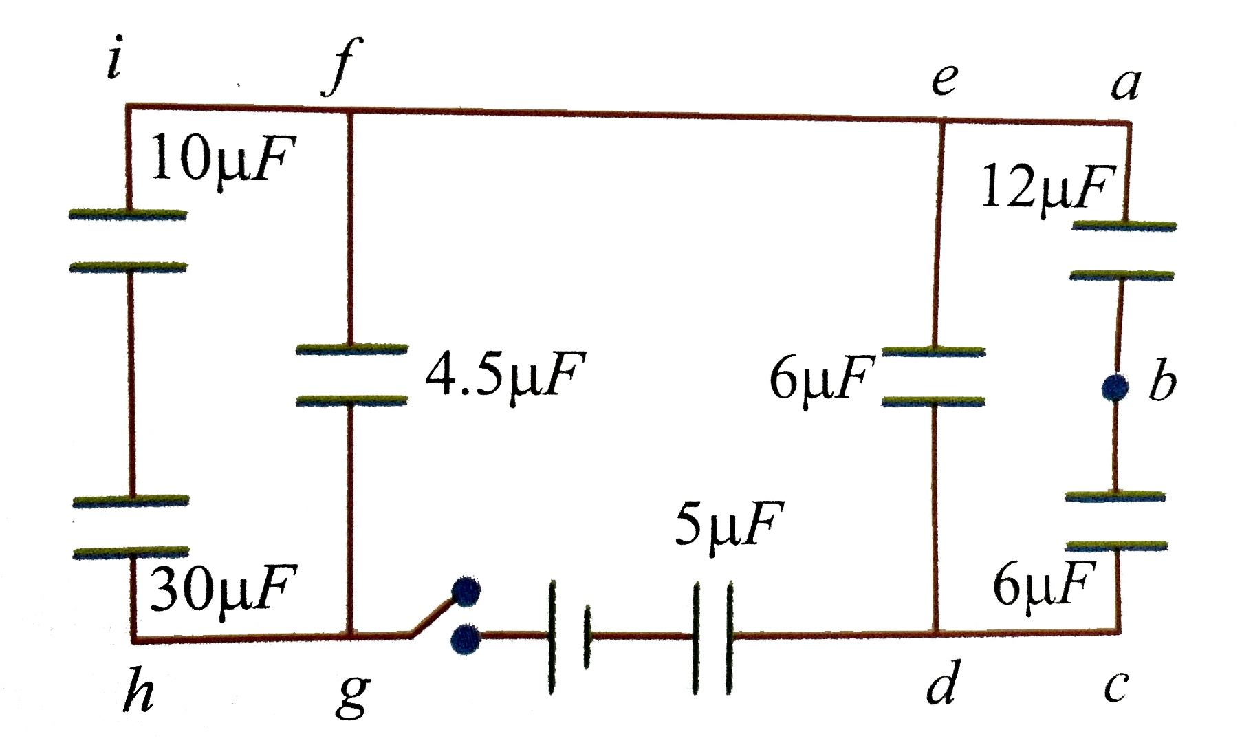 .
.
The emf `E` of the battery is :
View SolutionIn the circuit diagram shown here seven capacitors are connected to a source of emf `E`. Initially, the switch `S` is closed and steady state attained. Now, the potential difference between the points 'a' and 'b' is `4` volt. Now, answer the following :
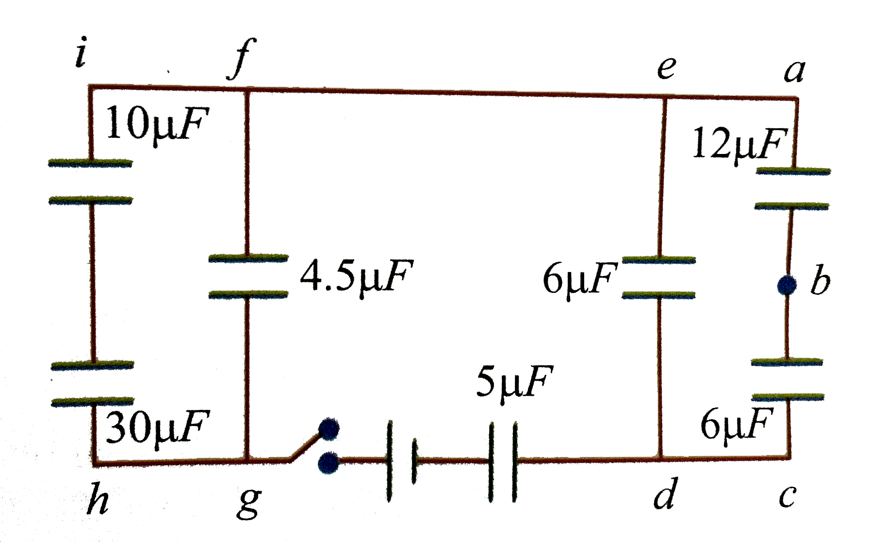 .
.
The charge on `4.5 mu F` is :
View SolutionIn the circuit diagram shown here seven capacitors are connected to a source of emf `E`. Initially, the switch `S` is closed and steady state attained. Now, the potential difference between the points 'a' and 'b' is `4` volt. Now, answer the following :
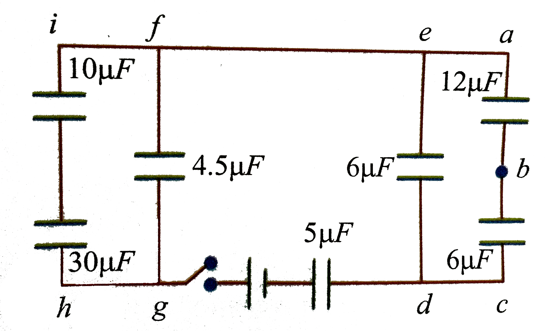 .
.
The charge on `10 mu F` is :
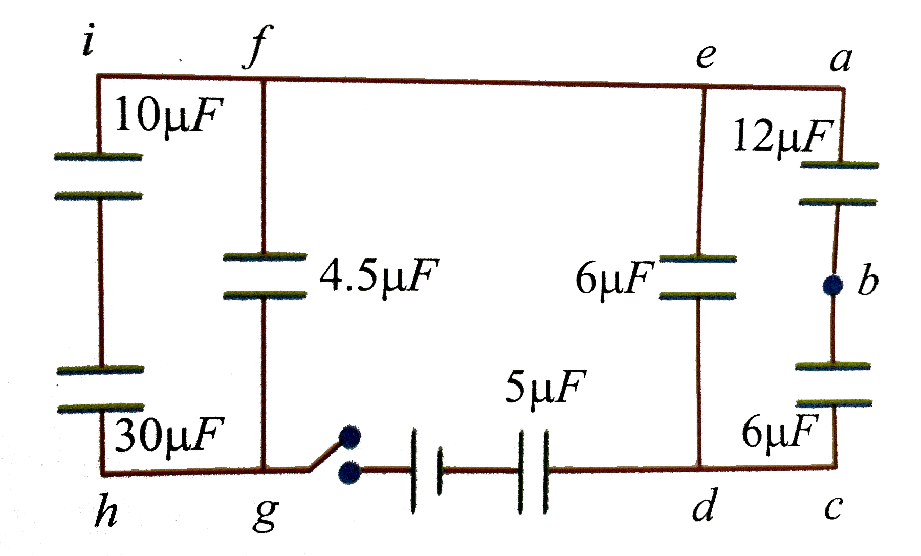
View SolutionIn the circuit diagram shown here seven capacitors are connected to a source of emf `E`. Initially, the switch `S` is closed and steady state attained. Now, the potential difference between the points 'a' and 'b' is `4` volt. Now, answer the following :
 .
.
The charge on `5 muC` is :
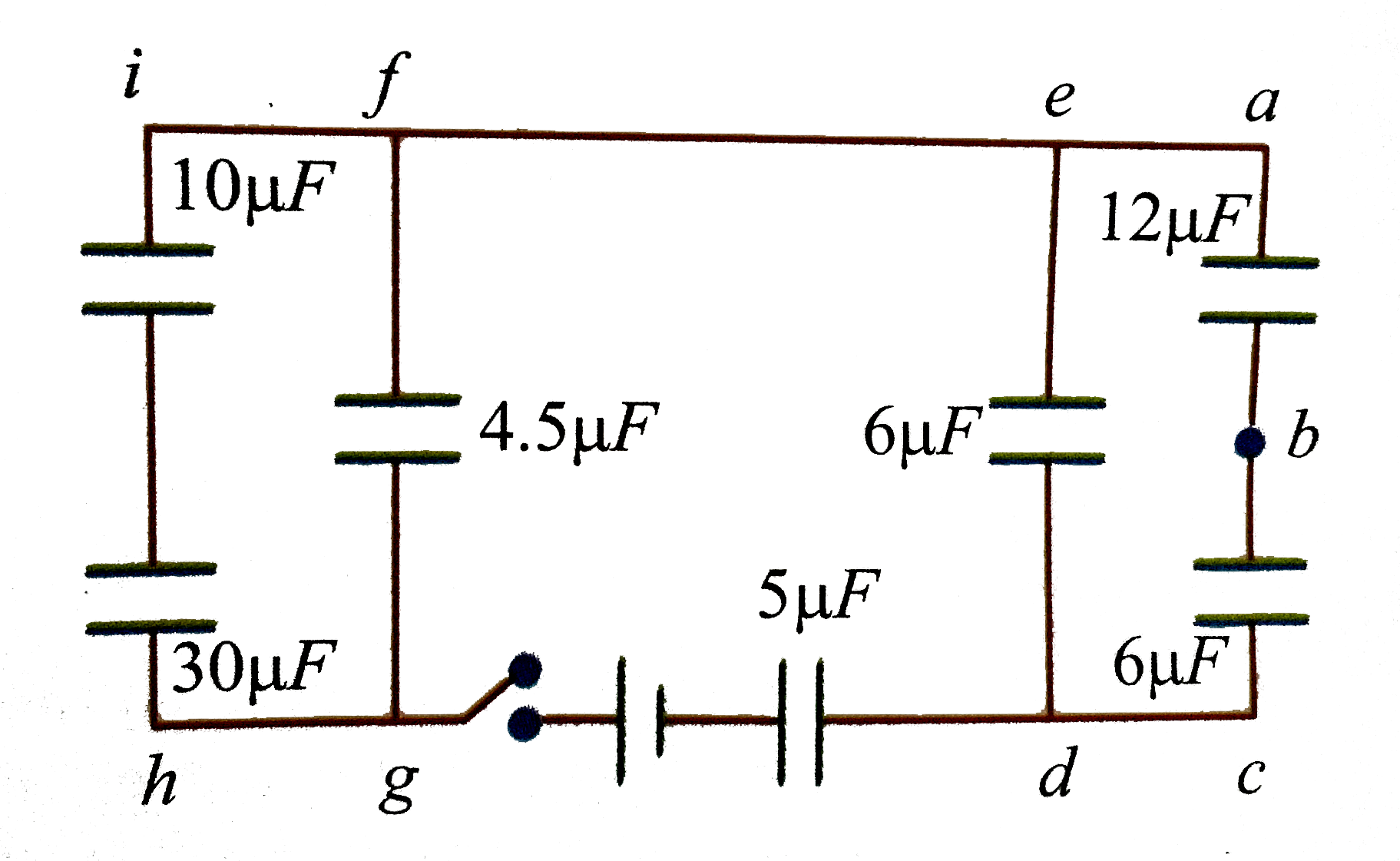
View SolutionIn the circuit diagram shown here seven capacitors are connected to a source of emf `E`. Initially, the switch `S` is closed and steady state attained. Now, the potential difference between the points 'a' and 'b' is `4` volt. Now, answer the following :
 .
.
The charge on `12 mu F` is :
View SolutionFour capacitors `C_(1)(=1 muF),C_(2)(=2muF),C_(3)(=3muF)` and `C_(4)(=4 muF)` are connected in a network as shown in the diagram. The emf of the battery is `E = 12 V` and its internal resistance is negligible. The keys `S_(1)` and `S_(2)` can be independetly put on or off. Indicate the charge on the capacitors by `q_(1),q_(2),q_(3)` and `q_(4)` respectively and the potential drops across them by `V_(1),V_(2),V_(3)` and `V_(4)` respectively.
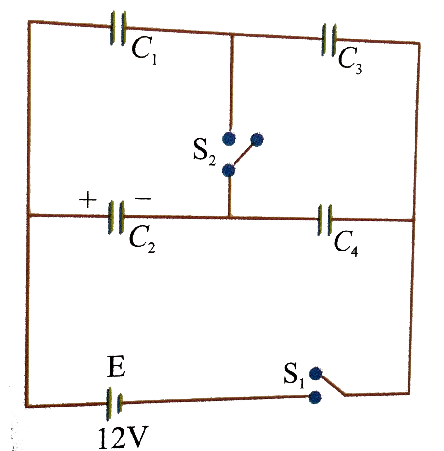
Initially both the keys are open. Then the key `S_(1)` is closed. Then the charges on the capacitors are.
View SolutionFour capacitors `C_(1)(=1 muF),C_(2)(=2muF),C_(3)(=3muF)` and `C_(4)(=4 muF)` are connected in a network as shown in the diagram. The emf of the battery is `E = 12 V` and its internal resistance is negligible. The keys `S_(1)` and `S_(2)` can be independetly put on or off. Indicate the charge on the capacitors by `q_(1),q_(2),q_(3)` and `q_(4)` respectively and the potential drops across them by `V_(1),V_(2),V_(3)` and `V_(4)` respectively.
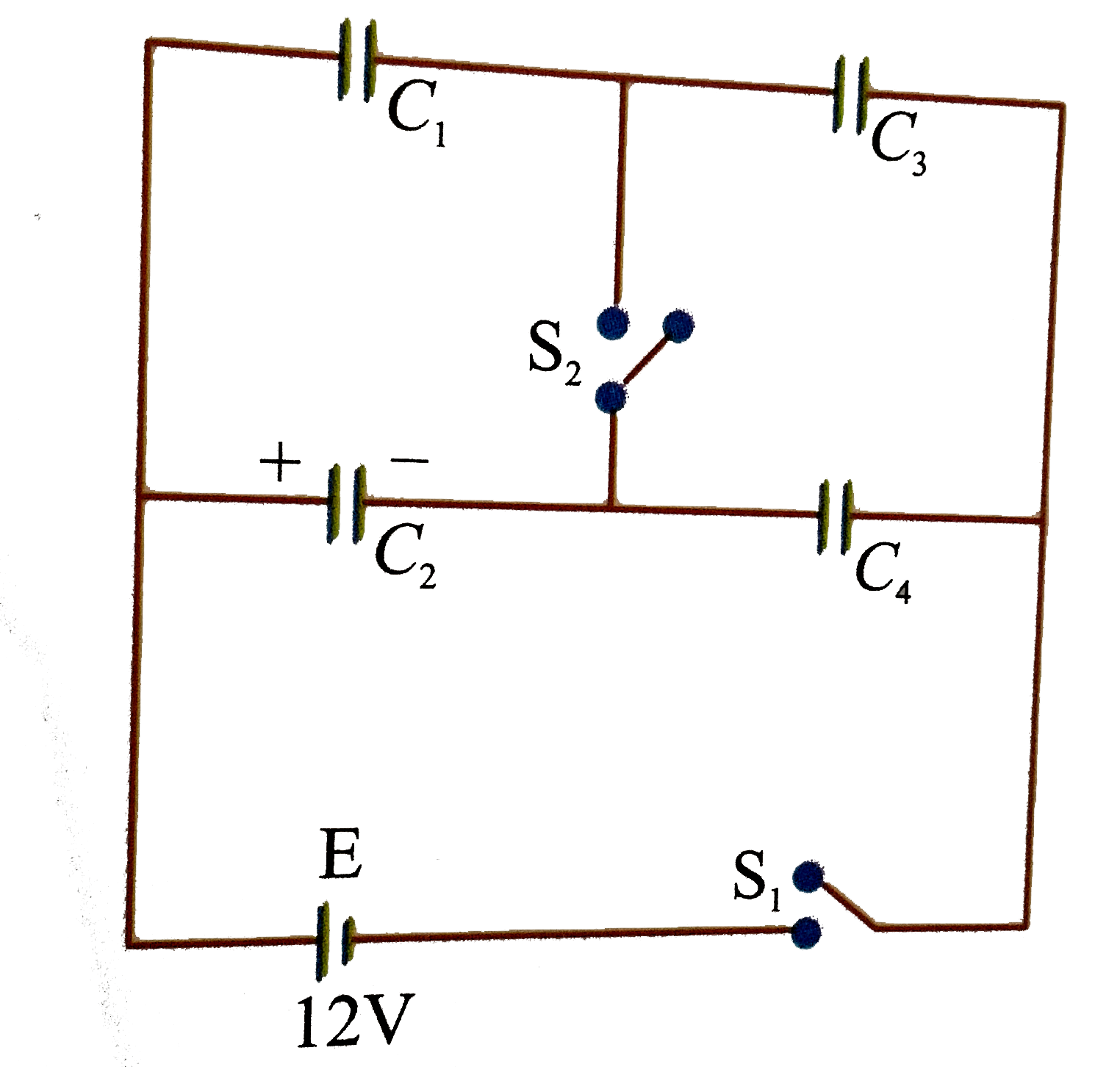
Initially key `S_(2)` is closed. Then the key `S_(1)` is now closed. Then the charges on the capacitors are.
View SolutionFour capacitors `C_(1)(=1 muF),C_(2)(=2muF),C_(3)(=3muF)` and `C_(4)(=4 muF)` are connected in a network as shown in the diagram. The emf of the battery is `E = 12 V` and its internal resistance is negligible. The keys `S_(1)` and `S_(2)` can be independetly put on or off. Indicate the charge on the capacitors by `q_(1),q_(2),q_(3)` and `q_(4)` respectively and the potential drops across them by `V_(1),V_(2),V_(3)` and `V_(4)` respectively.
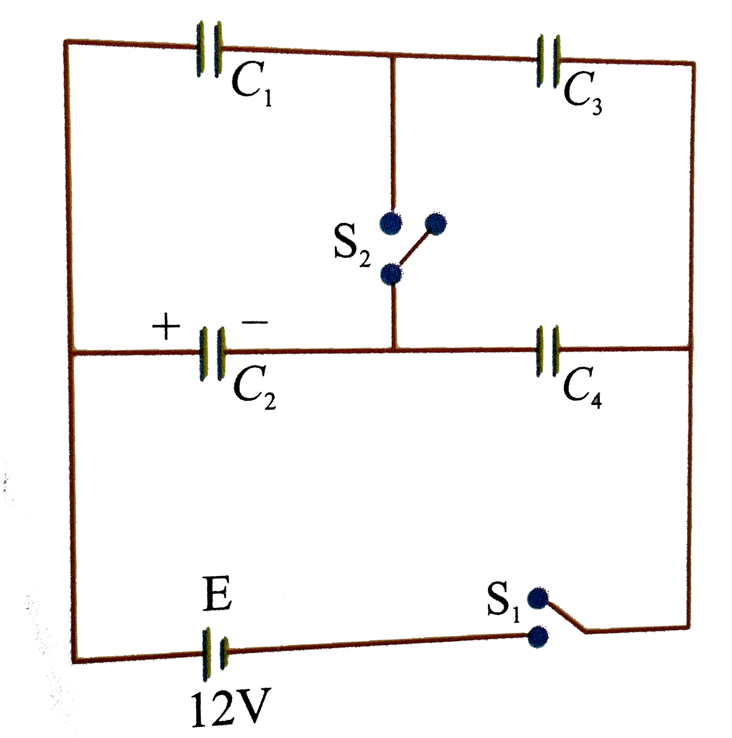
Initially key `S_(2)` is open. The key `S_(1)` is closed and teh capacitors are charged. If now key `S_(2)` be closed, the charge that will flow across this key is.
View Solution
Level-VI questions and complete solutions for chapter CAPACITANCE of NARAYANA PHYSICS (HINGLISH) of Class 12