Complete Solutions to Exercise of chapter CURRENT ELECTRICITY of Class 12 book with complete answers and questions
| Class 12 | PHYSICS |
| Chapter | CURRENT ELECTRICITY |
| PRADEEP | Exercise |
| Number Of Questions | 100 |
| Academic Year | 2023-24 |
A Steady current flows in a metallic conductor of non uniform cross section. The quantity/quantities which remain constant along the length of the conductor is/are
View SolutionA current of `4.4A` is flowing in a copper wire of radius `1mm` density of copper is `9 xx 10^(3)kg m^(-3)`and its atoms is `63.5u` If every atoms of copper contributes one condition electron , then the drift velocity of electrons is nearly [density of copper `9 xx 10^(3) kg m^(3)]`
View SolutionAn electron of hydrogen atoms is considered to be revolving round the proton in the circuit orbit of radius `(h^(2))/(2pi^(2)me^(2)) `with velocity` (2pie^(2))/(h)` the equivalent current due to circuiting charge is
View SolutionThe electron of a hydrogen atom revolves the proton in a circuit nth of radius `r_(0) = (in_(0) n^(2)h^(2))/(pi m e^(2)) ` with a speed `upsilon_(0) =(e^(2))/(2 in_(0) nh)` The current to circulating charge is proportional to
View SolutionA metal wire is subjected to a constant potential difference When the temperaturre of the metal in it wire increase the drift velocity of the electrons in it .
View SolutionThe mean free path of electrons in a metal is `4 xx 10^(-8)m` The electric field which can give on an average `2eV` energy to an electron in the metal will be in the units `V//m`
View SolutionThe current flowing through wire depends on time as, `I = 3t^(2) + 2t + 5`
The charge flowing through the cross - section of the wire in time `t = 0` to `t = 2` second is
View SolutionA uniform copper wire of length `1m` and cross section area `5 xx 10^(-7)m^(2)` carries a current of `1A`. Assuming that are `8 xx 10^(28)` free electron per `m^(3)` in copper, how long will an electron take to drift from one end of the wire an electron the other. Charge on an electron `= 1.6 xx 10^(-19)C`
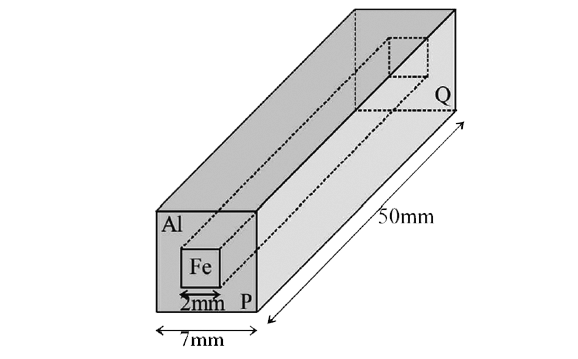
View SolutionIn an aluminium (Al) bar of square cross section, a square hole is drilled and is filled with iron (Fe) as shown in the figure. The electrical resistivities of Al and Fe are `2.7 xx (10^-8) Omega m and 1.0 xx (10^-7) Omegam,` respectively. The electrical resistance between the two faces P and Q of the composite bar is
View SolutionIn order to increase the resistance of a given wire of uniform cross section to four times its value, a fraction of its length is stretched uniformly till the full length of the wire because `3/2` times the original length. What is the value of this fraction?
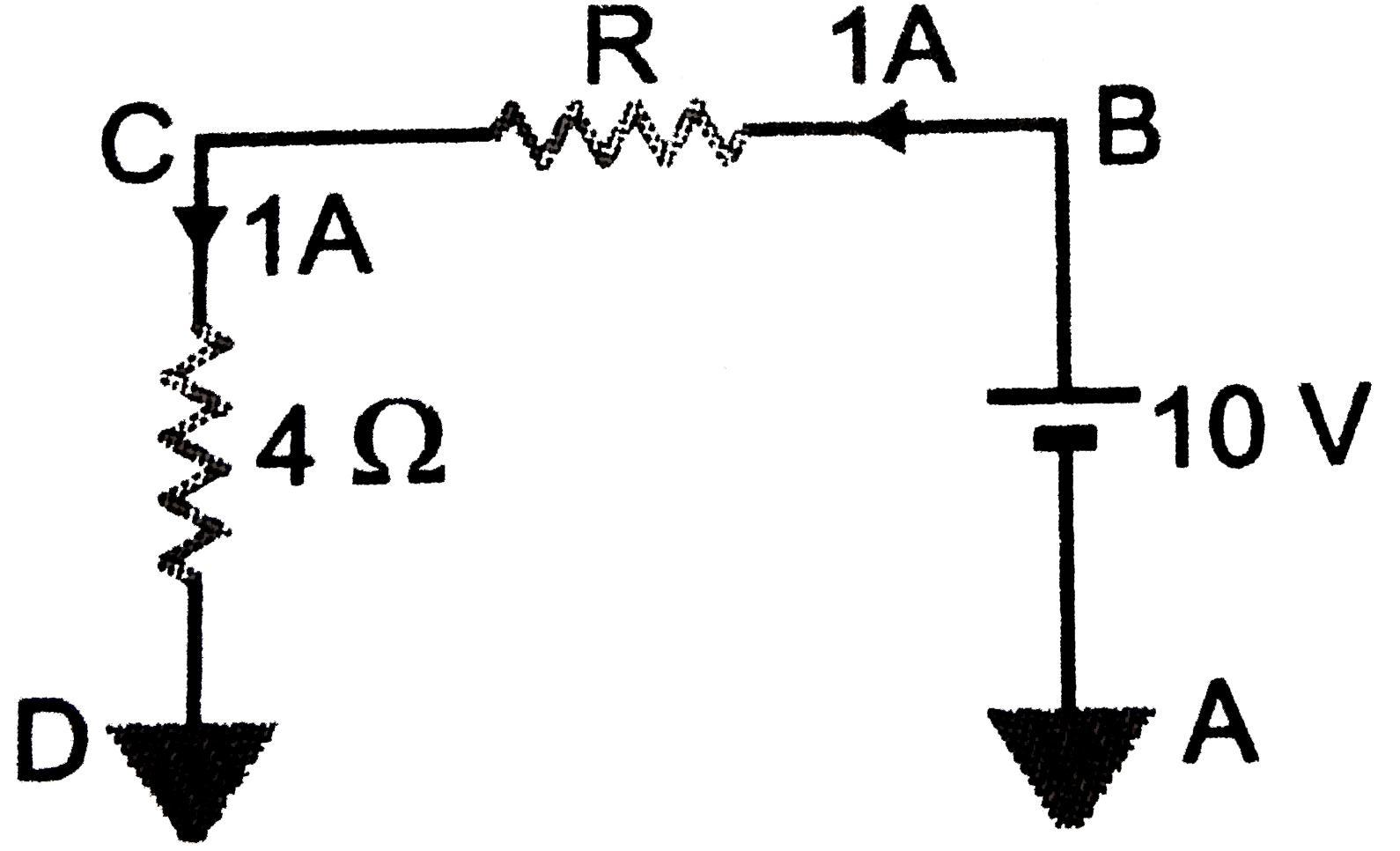
View SolutionThe potential at point B and C and the value of resistance `R` are
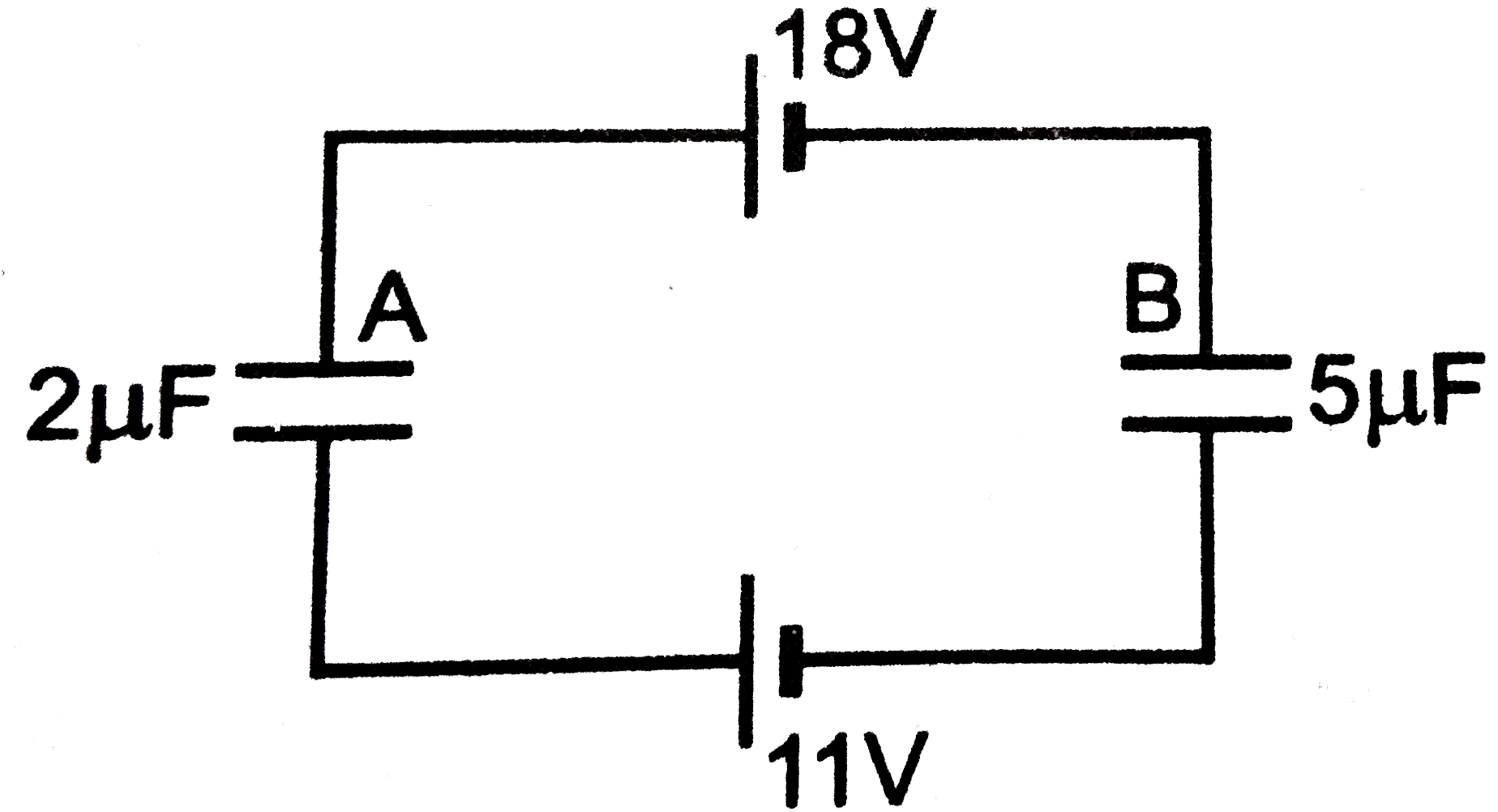
View SolutionTwo capacitors A and B of capacitances `2muF` and `5 mu F` are connected to two battery as shown in figure The potential difference in volt between the plate of A is
View SolutionThe resistance of a wire is 'R' ohm. If it is melted and stretched to `n` times its original length, its new resistance will be
View SolutionCopper and iron wire of same length and diameter are in series and connected acress a battery .The resistance of copper is about one sixth of that of iron If `E_(1)` and `E_(2)` are the electron fields of in the copper and iron wires respectively then which of the following is correct ?
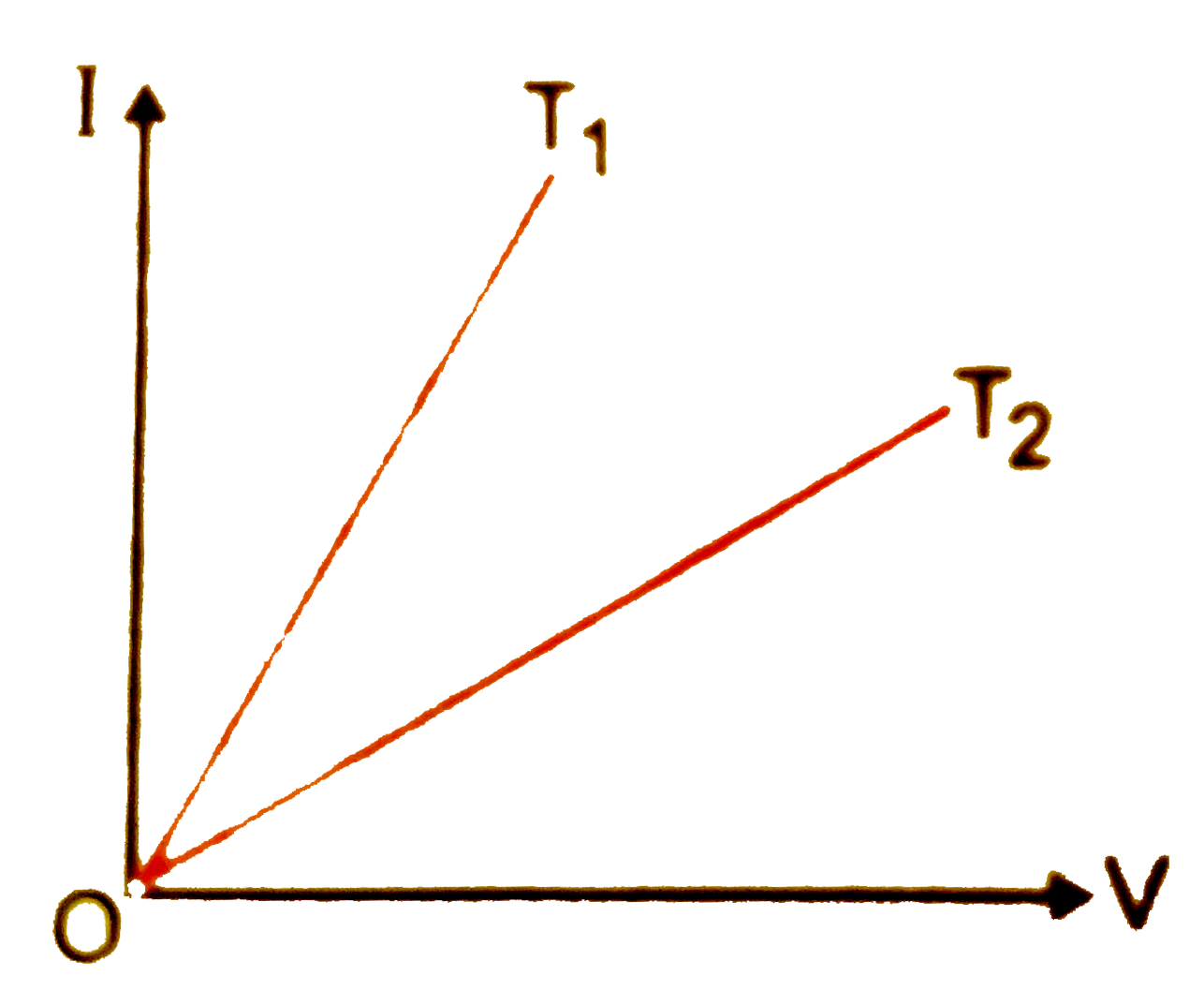
View SolutionV- I graph for a metallic wire at two different temperature `T_(1)` and `T_(2)` is shown in figure. Which of the two temperature is higher and why?
View SolutionWhen 5 V potential difference is applied across a wire of length 0.1 m, the drift speed of electrons is `2.5 xx 10^(-4) ms ^(-1)`. If the electron density in the wire is ` 8 xx 10^(28) m^(-3)`, the resistivity of the material is close to :
View SolutionAt `0^(@)C` the electron of conductor of a conductor `B` is `n` times that of conductor A temperature coefficient of resistance for A and B are `alpha_(1) and alpha_(2)` respectively the temperature coefficient of resistance of a circuit segment constant A and B in series is
View SolutionFollowing the above question the temperature coefficient of resistance of a circuit segment containing A and B in parallel is
View SolutionTwo conductors have the same resistance at `0^@C` but their temperature coefficient of resistanc are `alpha_1 and alpha_2`. The respective temperature coefficients of their series and parallel combinations are nearly
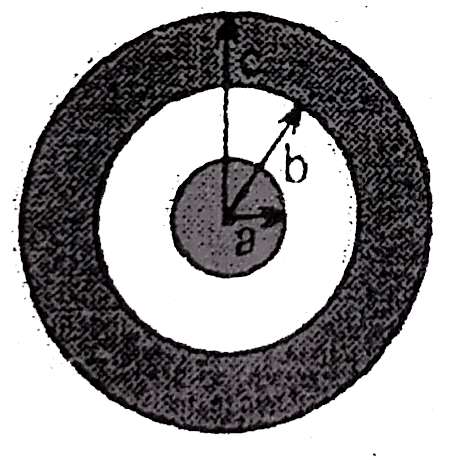
View SolutionA nonconducting sphere with radius a is concentric with and surrounded by a conducting spherical shell with inner radius b and outer radius c. The inner sphere has a negative charge uniformly distributed throughout its volume, while the spherical shell has no net charge. The potential V (r) as a function of distance from the center is given by
View SolutionThe temperature dependence of resistance of Cu and undoped Si in the temperature range `300 -400 K, ` is best described by :
View SolutionTwo metal wires of identical dimesnios are connected in series. If `sigma_(1)` and `sigma_(2)` are the conducties of the metal wires respectively, the effective conductivity of the combination is
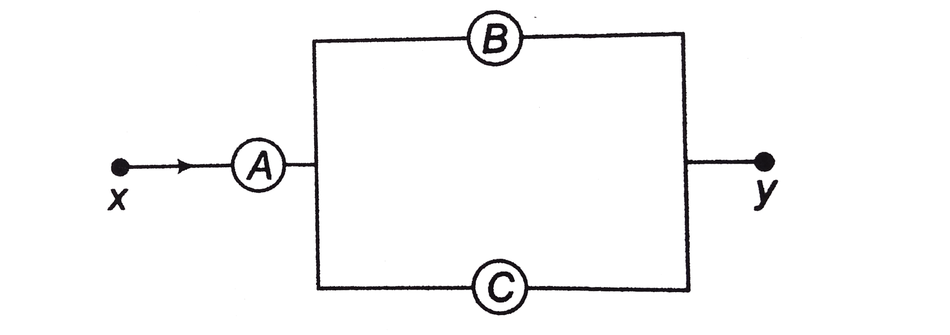
View Solution`A, B` and `C` are voltmeters of resistances `R, 1.5R` and `3R` respectively. When some potential difference is applied between `x` and `y` the voltmeter readings are `V_A, V_B`and `V_C,` then
View SolutionConsider an infinite ladder of network shown In fig 5.223. A voltage is applied between points A and B. If the voltage is halved after each section, find the ratio of `R_1//R_2`.
Suggest a method to terminate it after a few sections without introducing much error in its attenuation.
View SolutionThe reading of an ammeter in the circuit
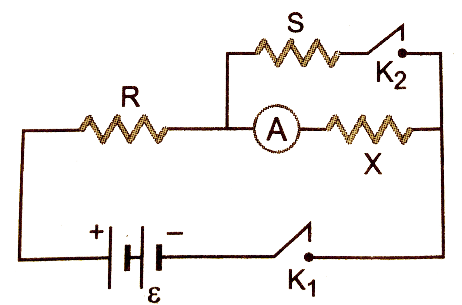
(i) `I` when key `K_(1)` closed key `K_(2)` is open
(ii) `I//2` when both keys `K_(1) and K_(2)` are closed Find the expression for the resistance of `X` in terms of the resistances of R and S
View SolutionIn the circuit `AB` is a long wire of `300 Omega` it is tapped at one third distance and is connected as shown The equivalent resistance between A and B is
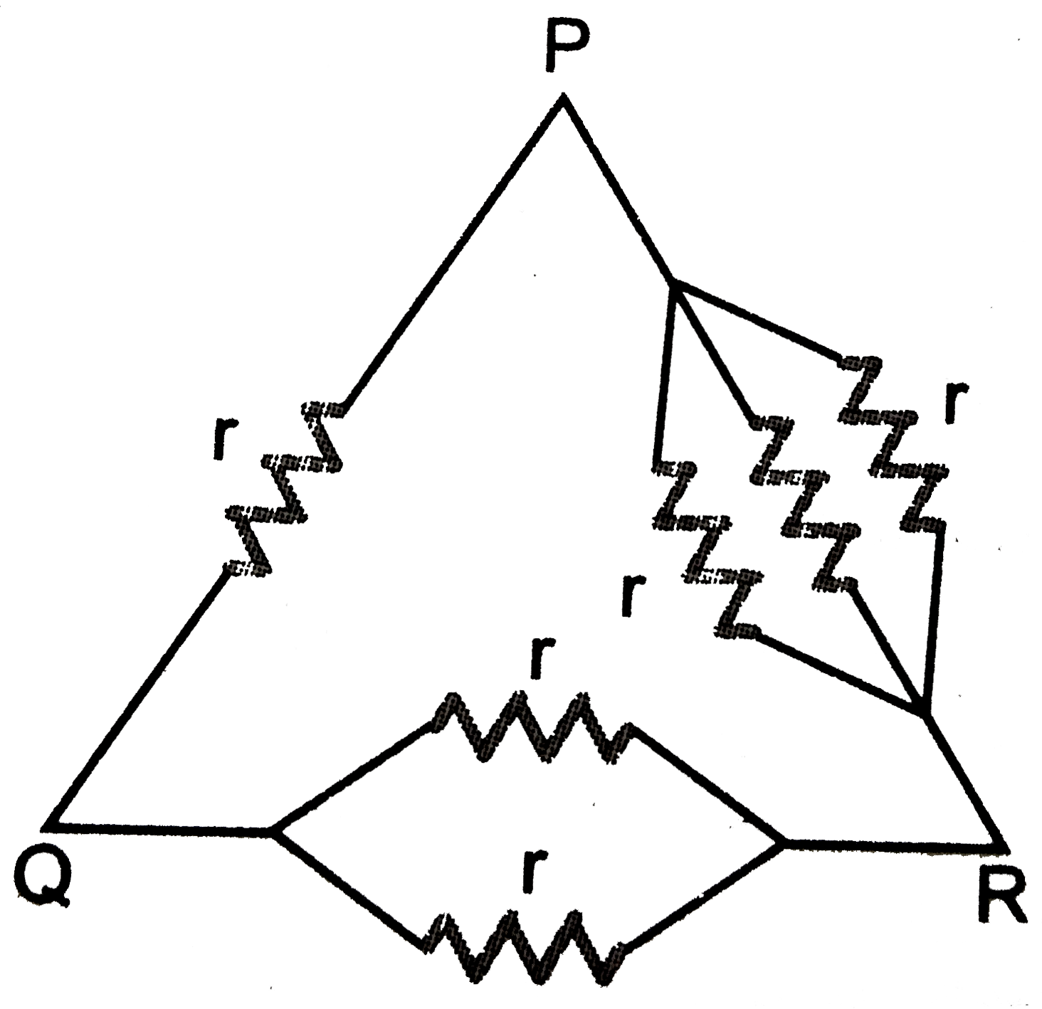
View SolutionSix equal resistance are connected between point `P,Q and R` Then net resistance will be maximum between
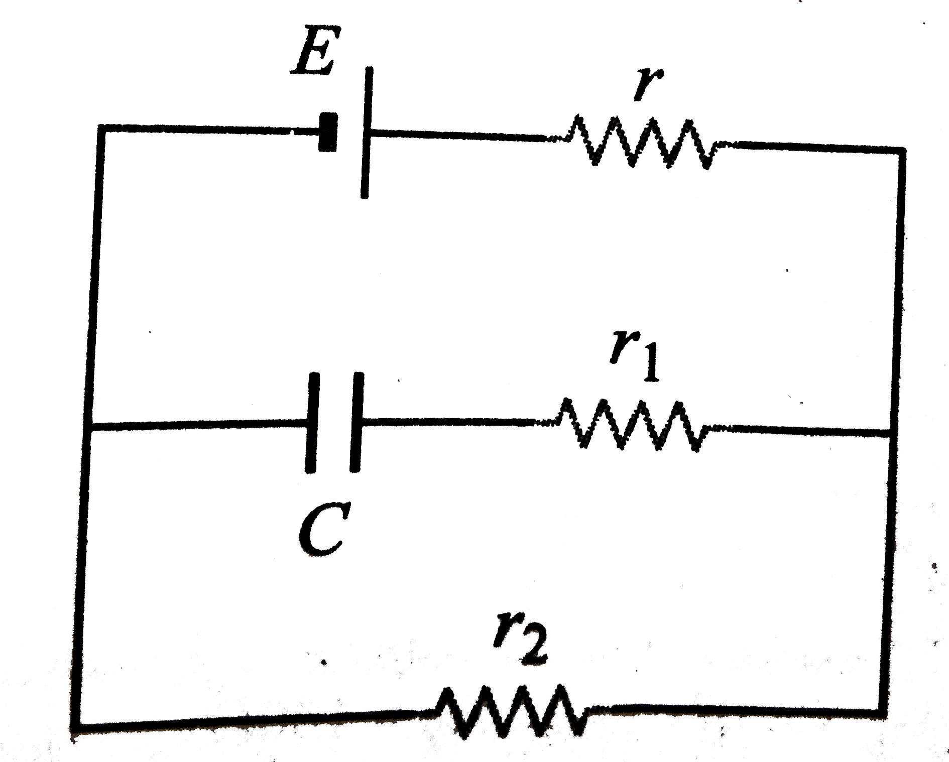
View SolutionIn the given circuit digram when the current reaclies steady state in the circuit , the charge an the capacity of capacitance `C` will be
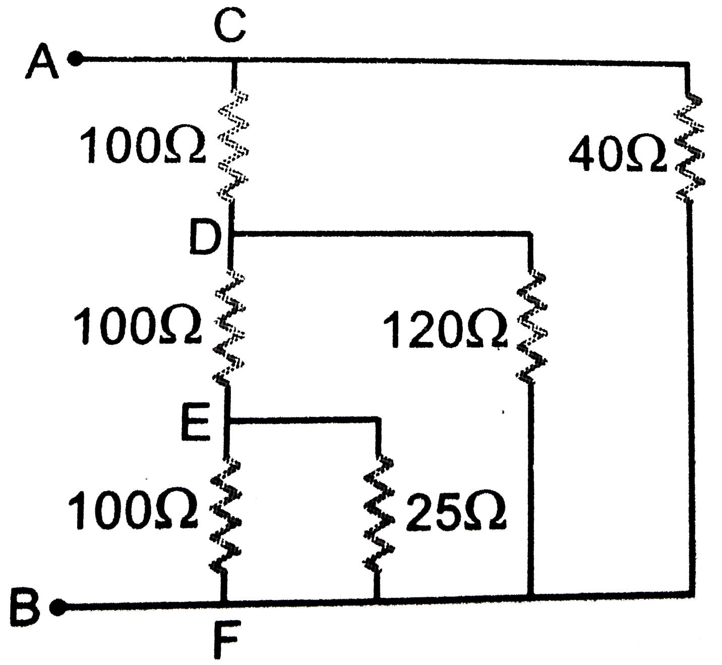
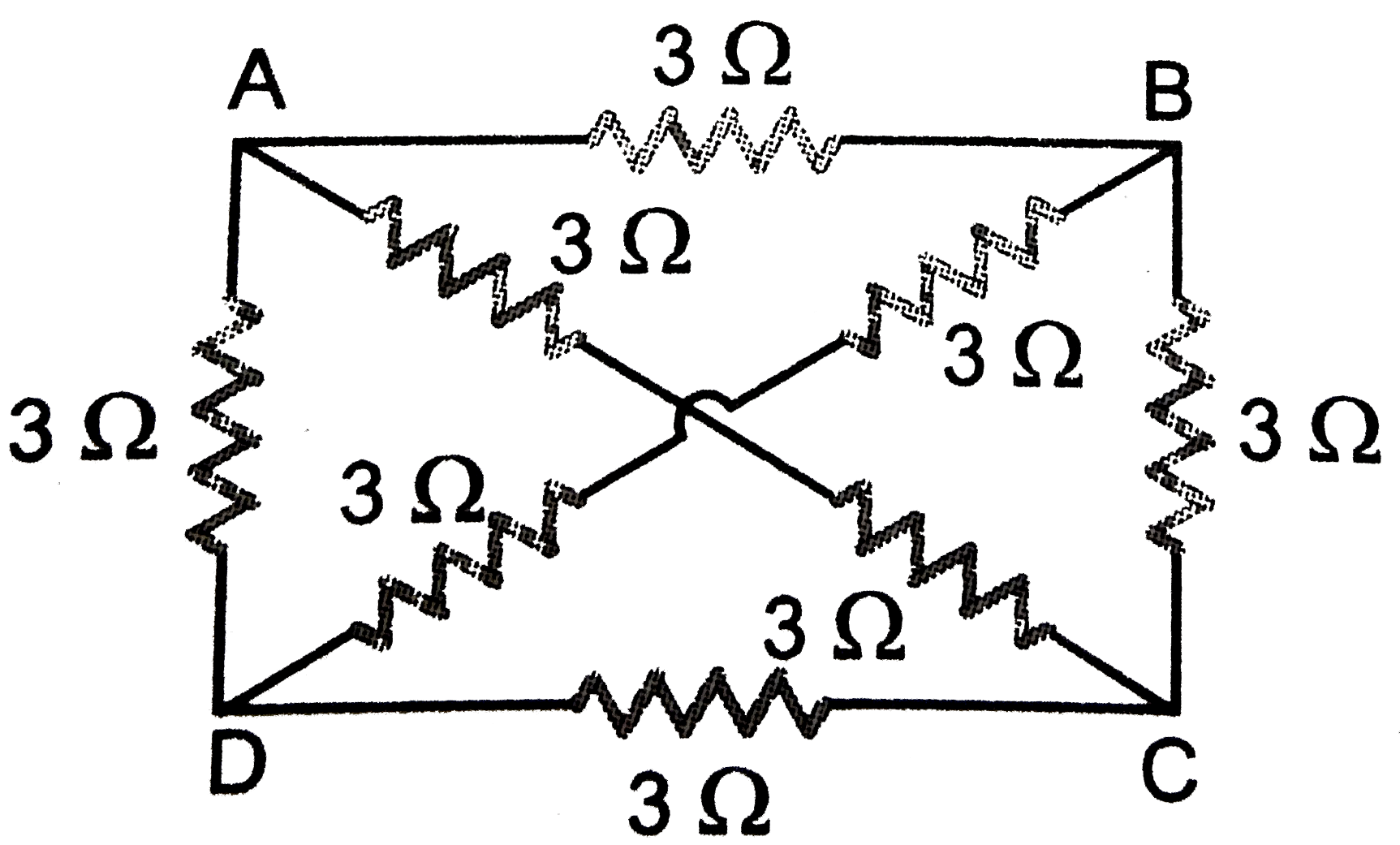
View SolutionThe resistance between point `A` and `C` below is
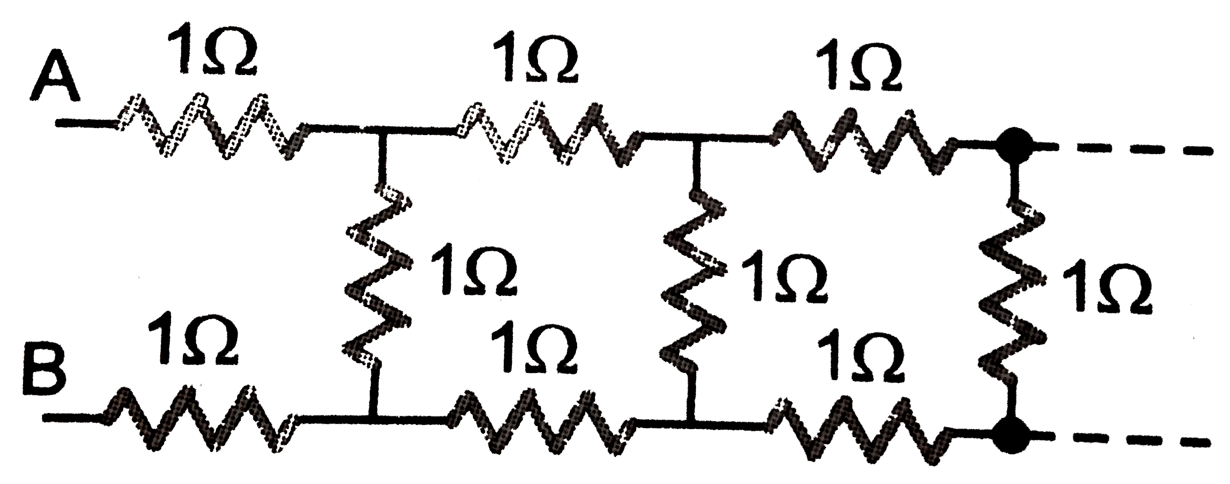
View SolutionThe resistance between the terminal point A and B of the given infinitely long circuit will be
View SolutionThe reading of ammeter
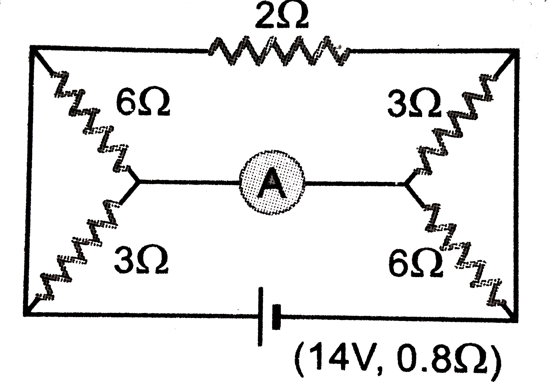
View SolutionThe equivalent resistance between point A and B of an infinite net work of resistances each of `1 Omega` connected

View SolutionIn the circuit shown the cell is idea with end `=15V` each resistance is of `3Omega` The potential difference the capacitor is
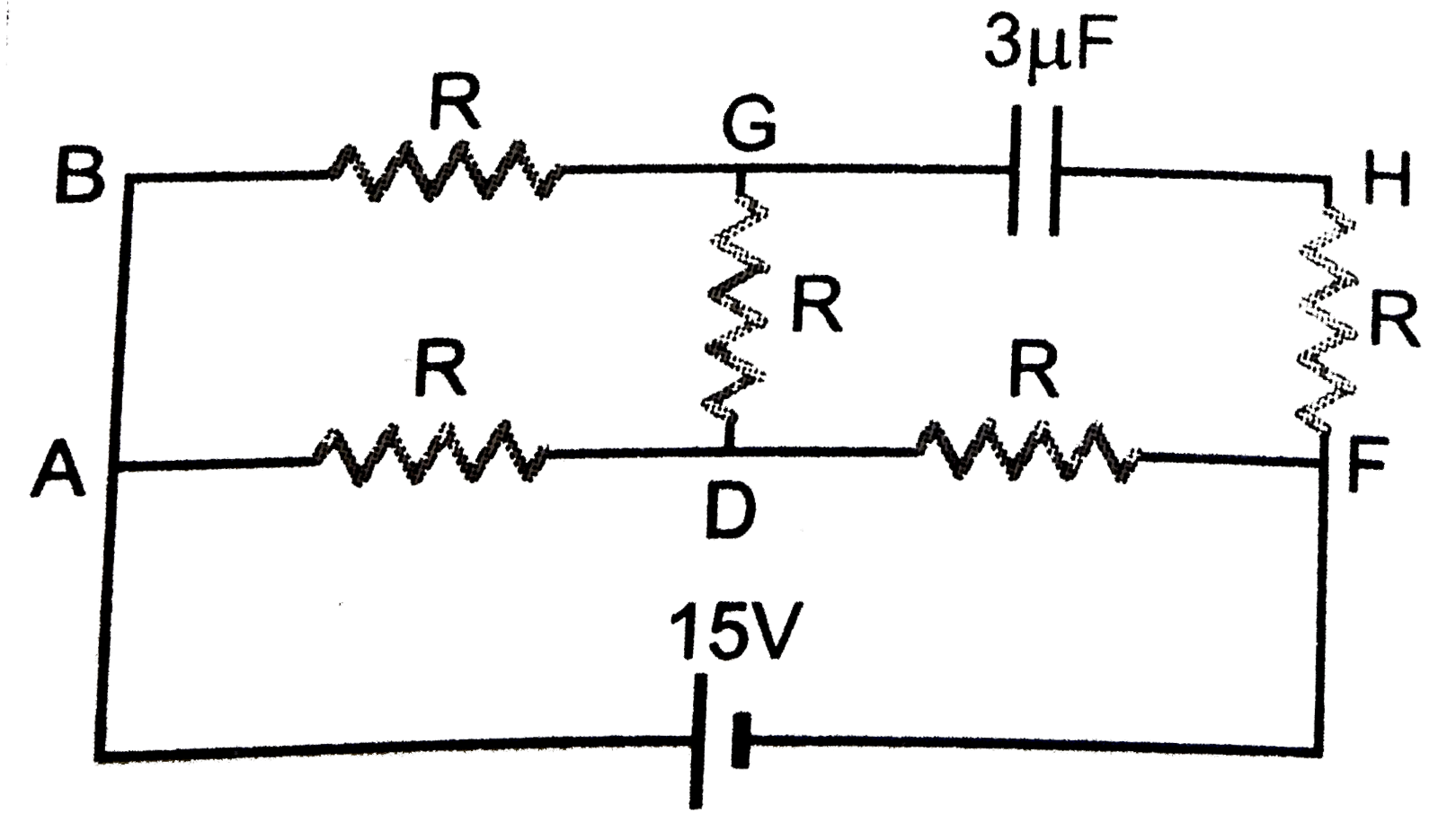
View SolutionThe equivalent resistance between point A and B for the combination of resistance
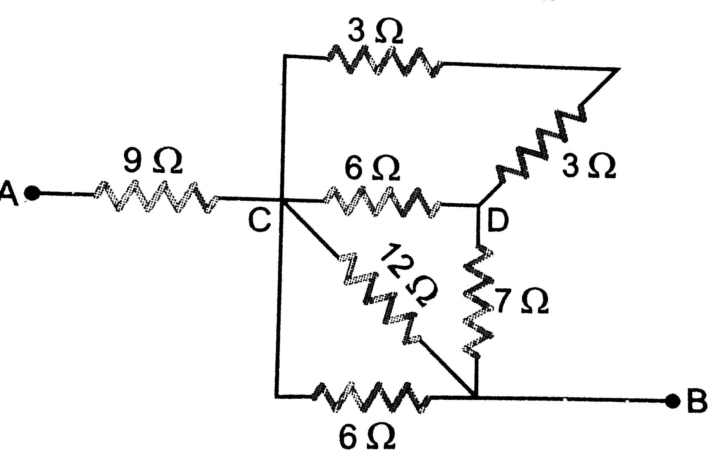
View SolutionAn electric of `5A` is passing through a circuit contaning three arrengement in parallel if the length and radius of the wires are in the ratio `2:3:4 and 3:4:5` then the ratio of current passing through wires should be
View SolutionShows a network of eight resistors battery of resistance `R(= 2 Omega)` connected in a `3V` battery of negligible internal resistance. The current `I` in the circuit is
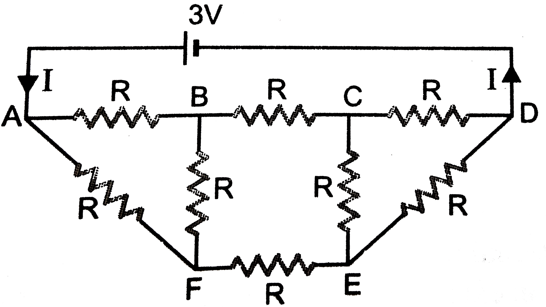
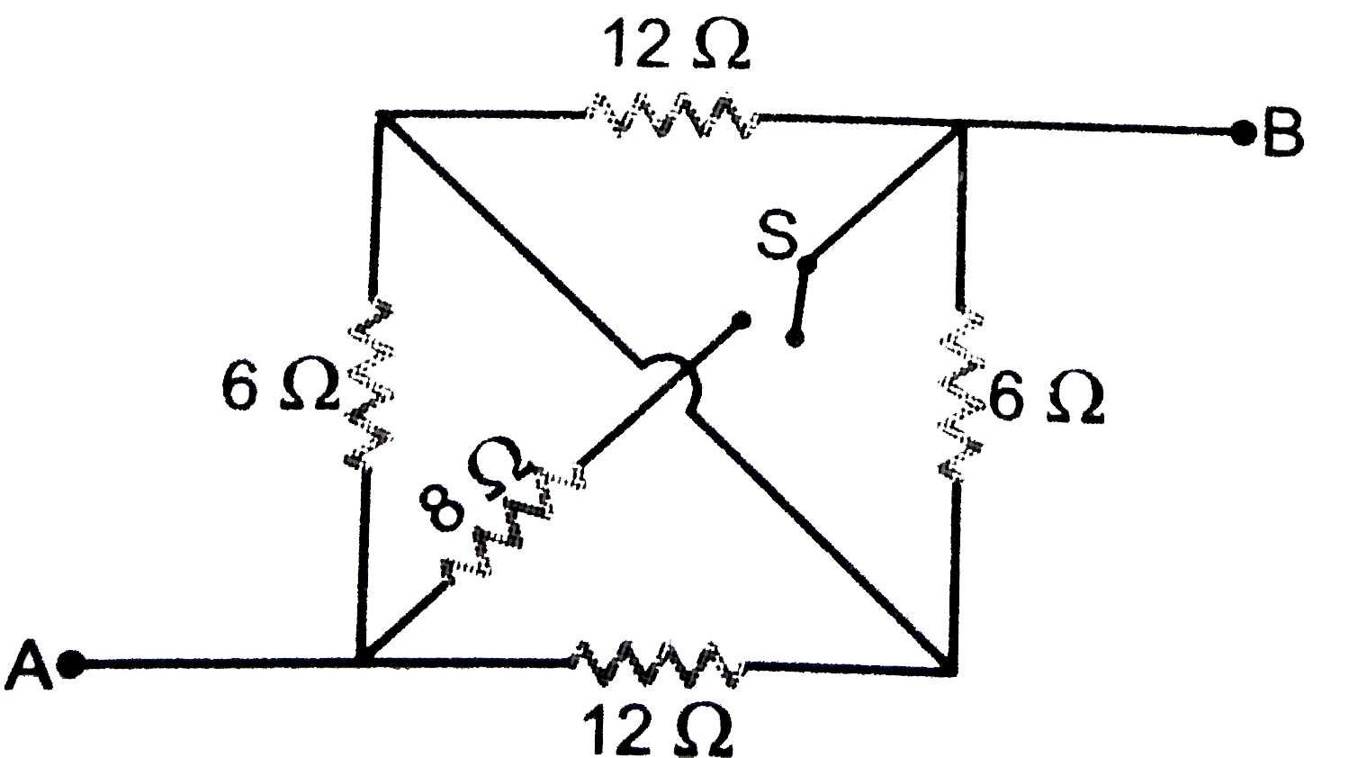
View SolutionThe equivalent resistance between point A and B with swich `S` open and closed are resistance
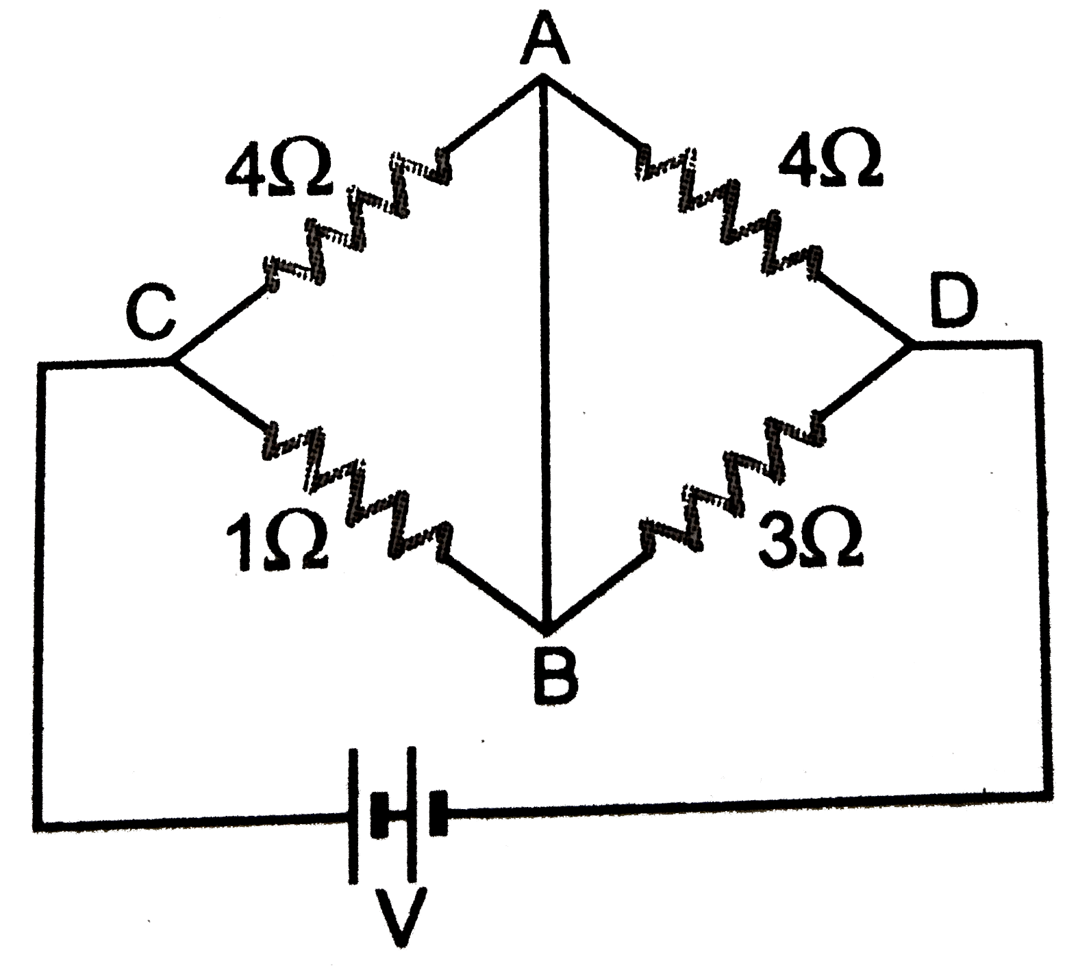
View SolutionA galvanometer of resistance `G` is shunted by a resistance `S` `ohm`. To keep the main current in the circuit uncharged, the resistance to be put in series with the galvanometer
View SolutionIn the circuit of a condacting wire is connected between point A and B the current is this wire will
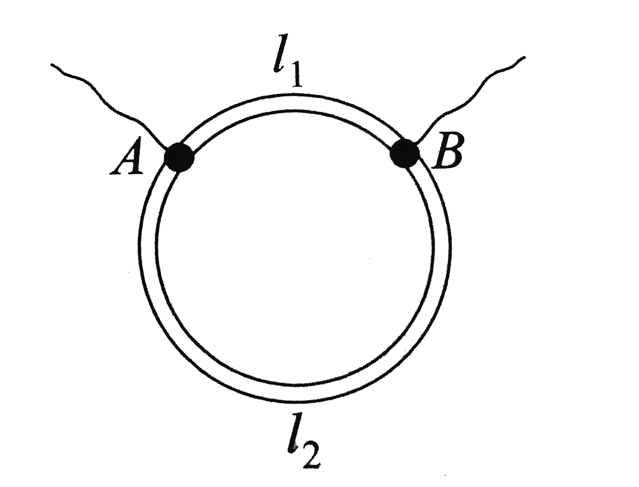
View SolutionA ring is made of a wire having a resistance `R_(0) = 12 Omega`. Find the point `A` and `B`, as shown in the figure, at which a current carrying conductor should be connected so that the resistance `R` of the subcircuit between these points is equal to `(8)/(3) Omega`
View SolutionThe internal resistance of primary cell is `4Omega` it generater a current of `0.2A` in which chemical resistance connected is providing the current is
View SolutionA student measure the terminal potential difference `(V)` of a cell (of `emf` internal energy is connected in providing the circuit is
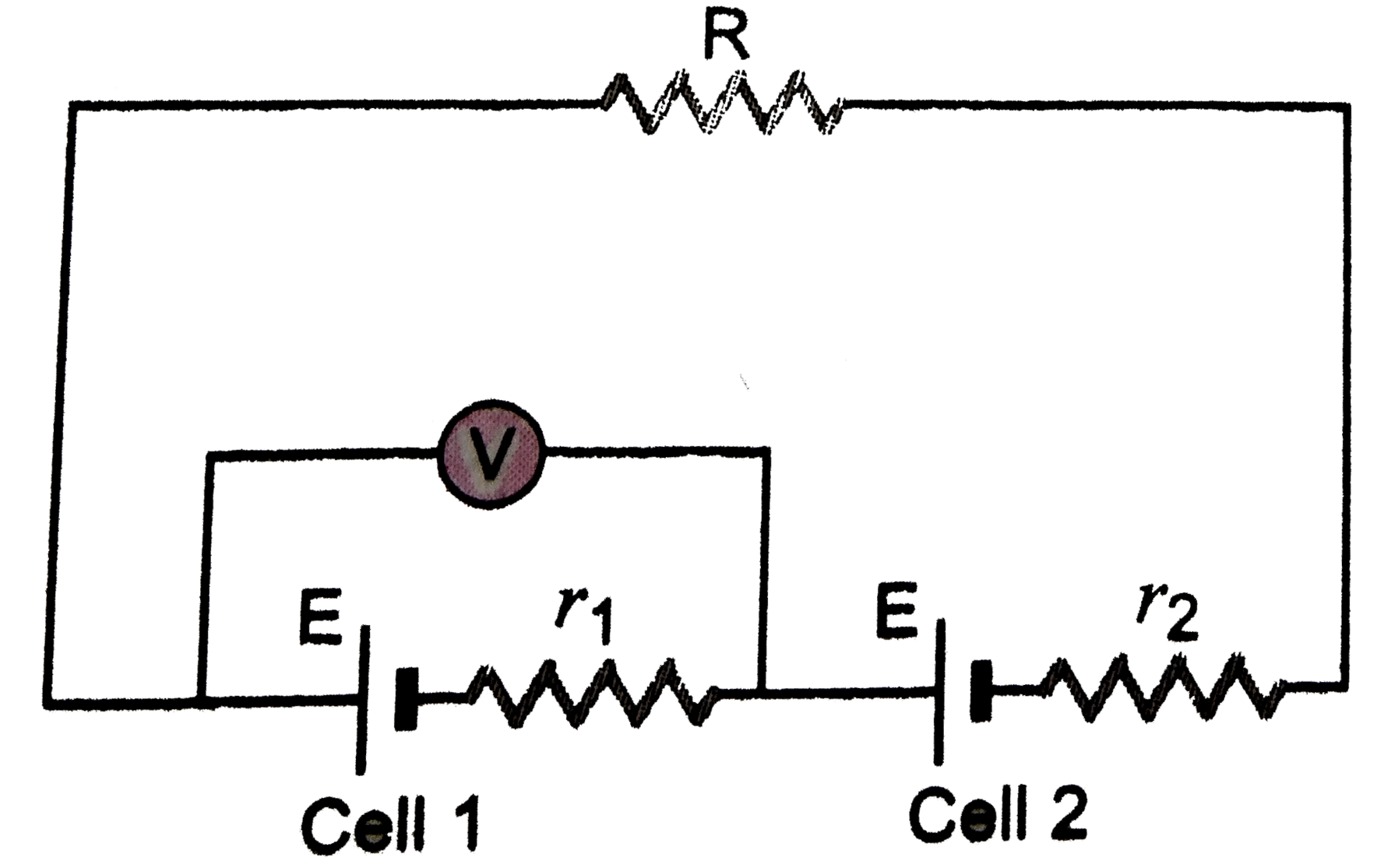
View SolutionIn the circuit cell are of equal `emf E` but of difference internal resistance `r_(1) = 6 Omega` reading of the ideal voltmeter connected across cell `1` is zero The value of the external resistance `R` is ohm is equal to
View SolutionCell having an `emf epsilon ` internal resistance `r` is connected a variable external resistance `R` As the resistance `R` is increased the piot of potential difference `V` across `R` is given by
View SolutionIn the arrangement the current through `5 Omega` resistor is
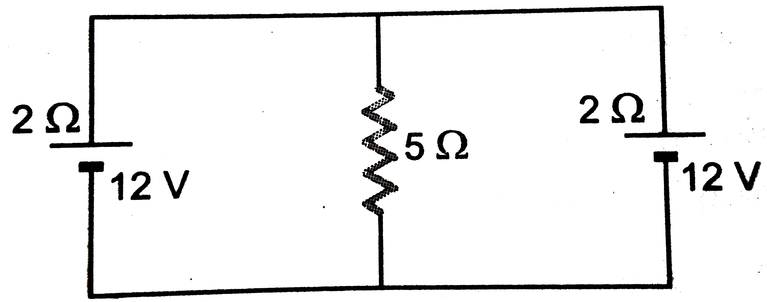
View SolutionIn the following circuit the current in each resistance is
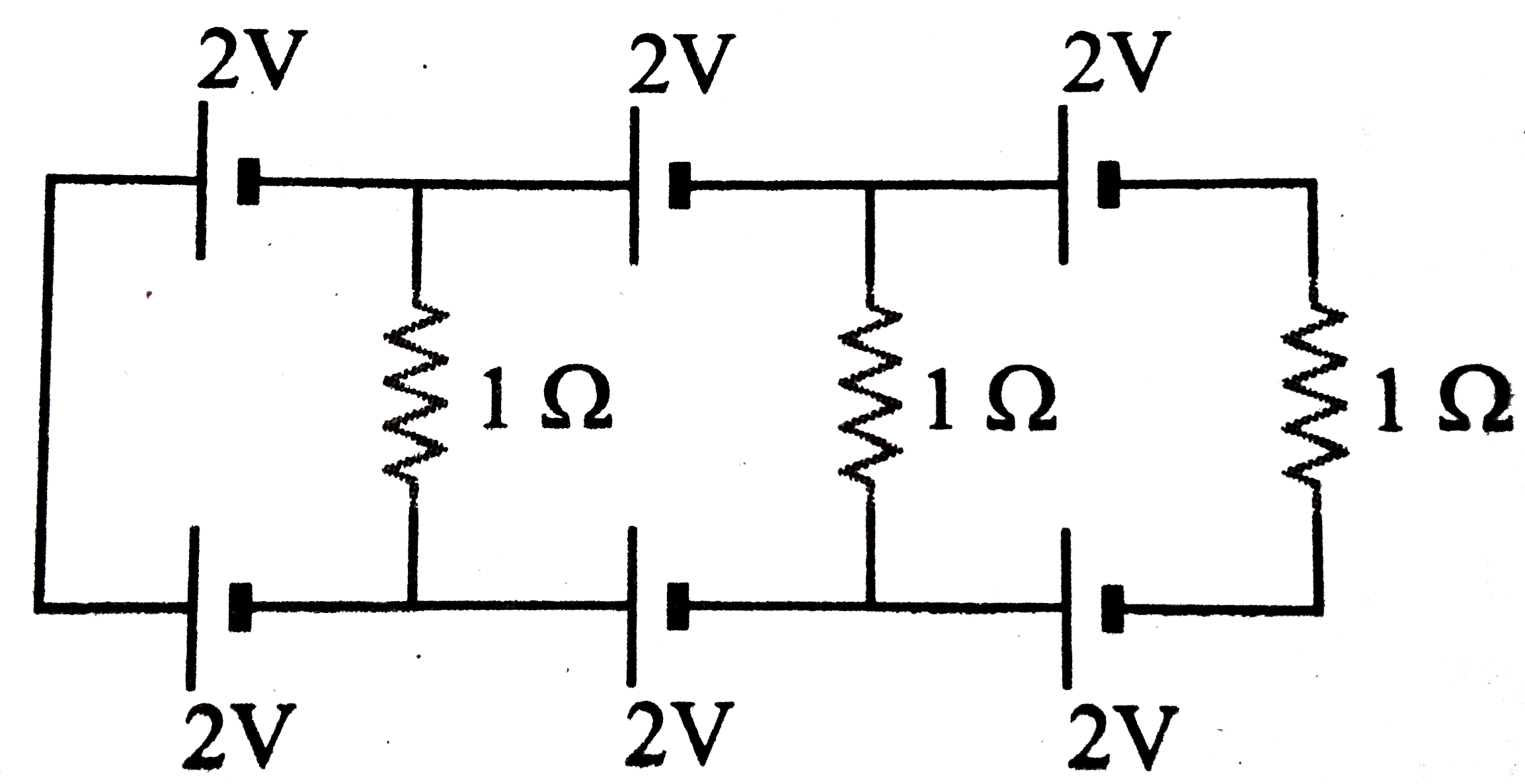
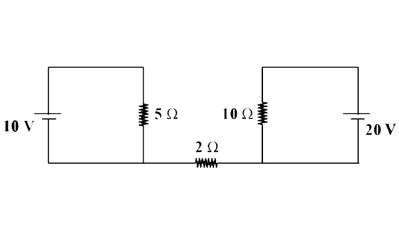
View SolutionFind out the value of current through `2Omega` resistance for the given circuit.
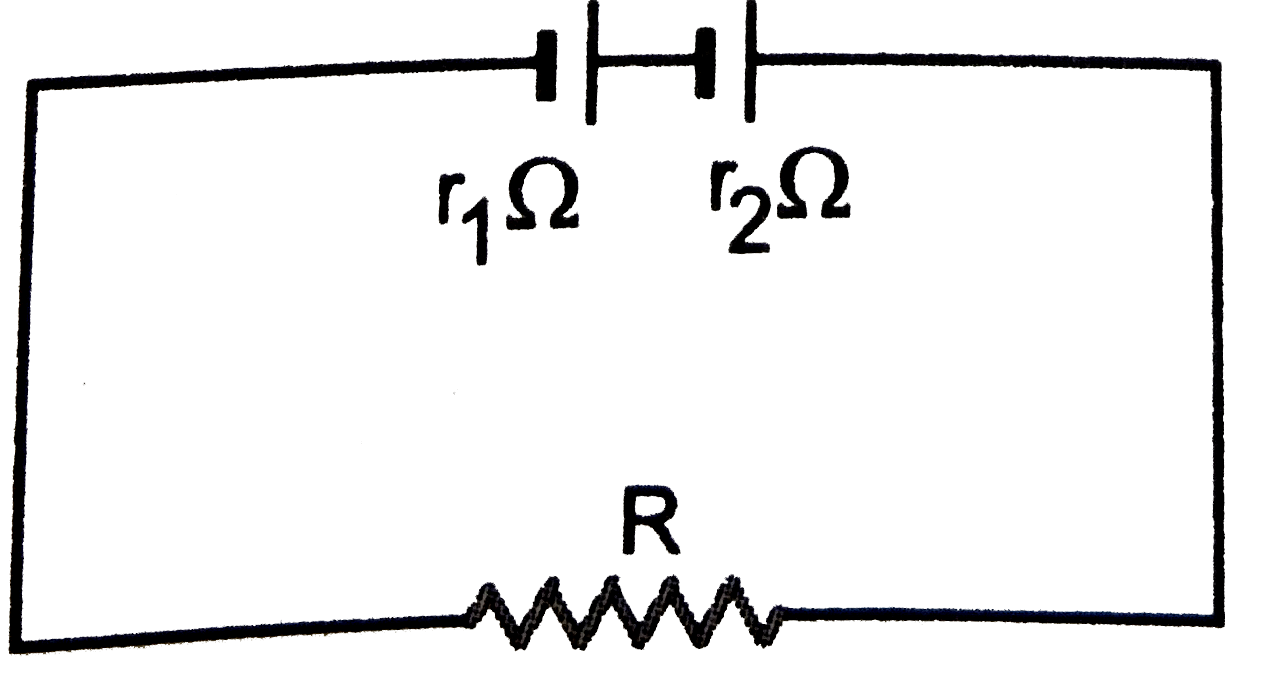
View SolutionTwo cell with the same e.m.f. E and difference internal resistance `r_(1) and r_(2)` are connected in series to an external resistance `R` a value of `R` be selected such that the potential difference as the flow cell E should be zero when
View SolutionTwelve cells each having the same e.m.f are connected in series and are kept to a closed box. Some of the cell are connected in reverse order .The battery is connected in series with an ammeter an external resistance `R` and two cells of the same type as an in the battery .The current when they and support each other is `3` ampere and current is `2` ampare when the two oppose each other. How many cells are connected in servese order ?
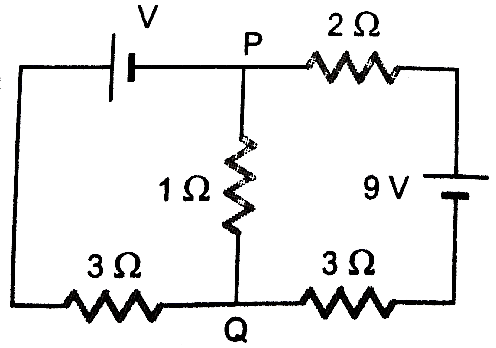
View SolutionIn the circuit shown, the currect in the `1 Omega` resistor
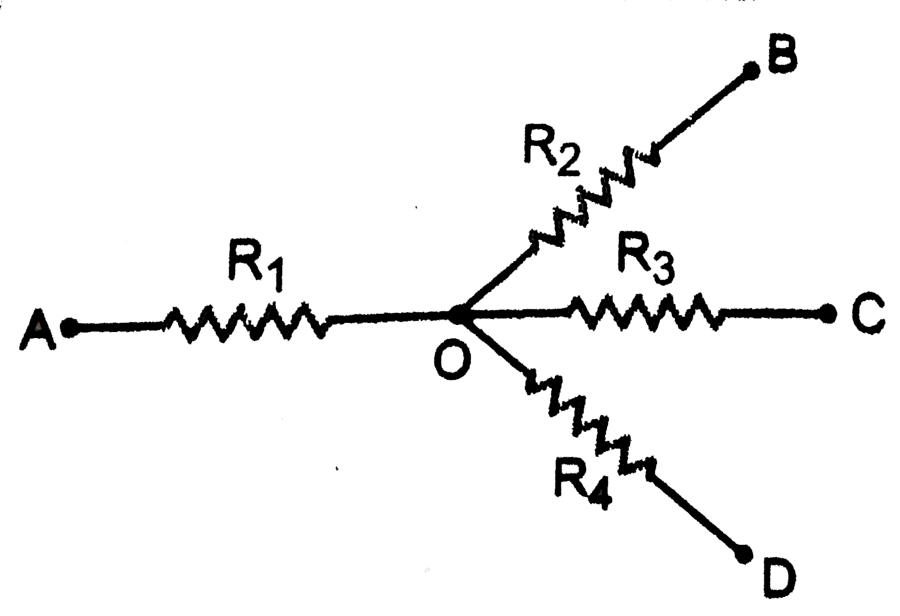
View SolutionIn the `R_(1) = 10 Omega ,R_(2) = 20 Omega, R_(3) = 40 Omega R_(4) = 80 Omega` and `V_(A) = 5V,V_(B) = 10V,V_(c) = 20V,V_(D) = 15V` The current in the resistance `R_(1)` will be
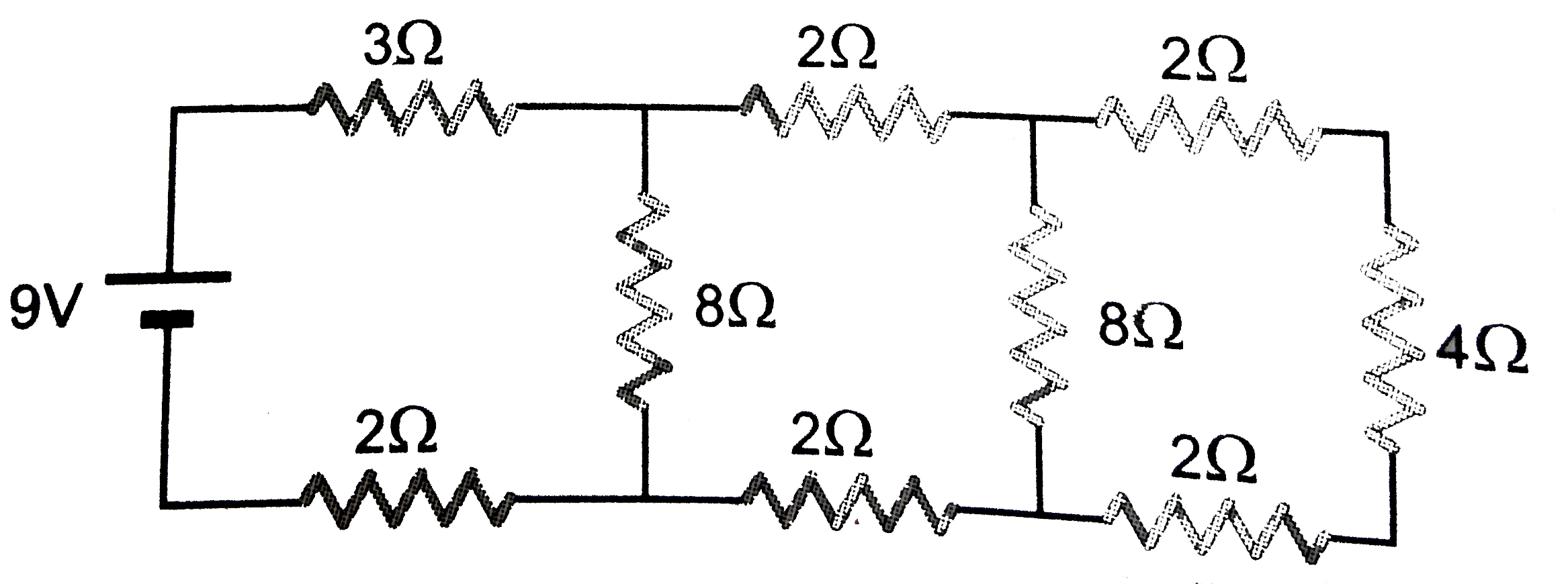
View SolutionIn the circuit shown in the circuit through
View SolutionIn the circuit `E,F,G,H`are cell of `emf` `2,1,3`and `1 Omega` respectively .The potential difference across the terminal of each of the cell `G` and `H` are

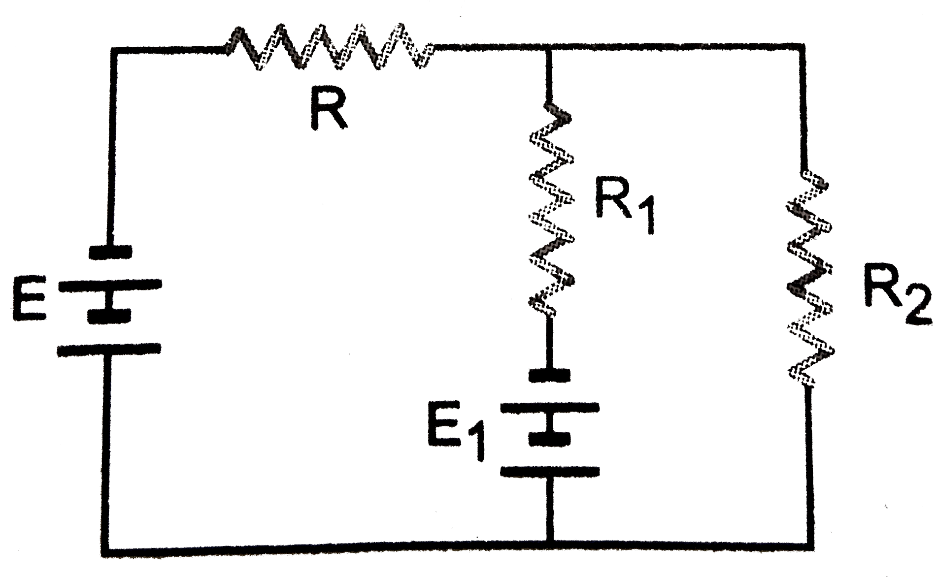
View SolutionShown a circuit with known resistance `R,R_(1)` and `R_(2)` neglect the resistance of the conducting wires and internal resistance of current source The magnitude of electrotive force `E_(1)` each that the currect `l` through the resistance `R` in zero will be
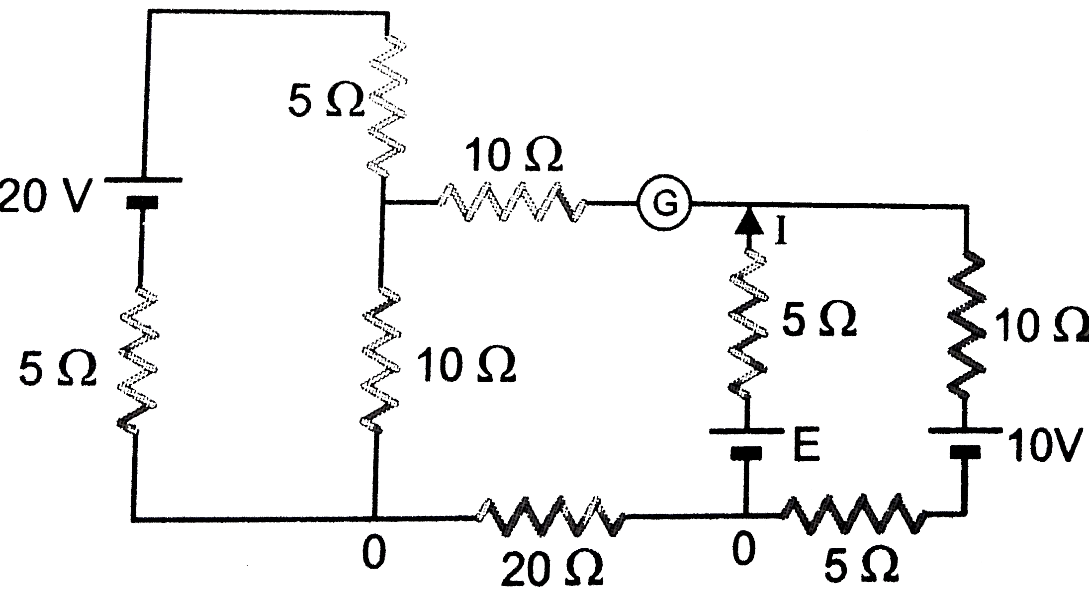
View SolutionWhat would be the value of `E` so that the galvanometer `G` circuit shown on deflection
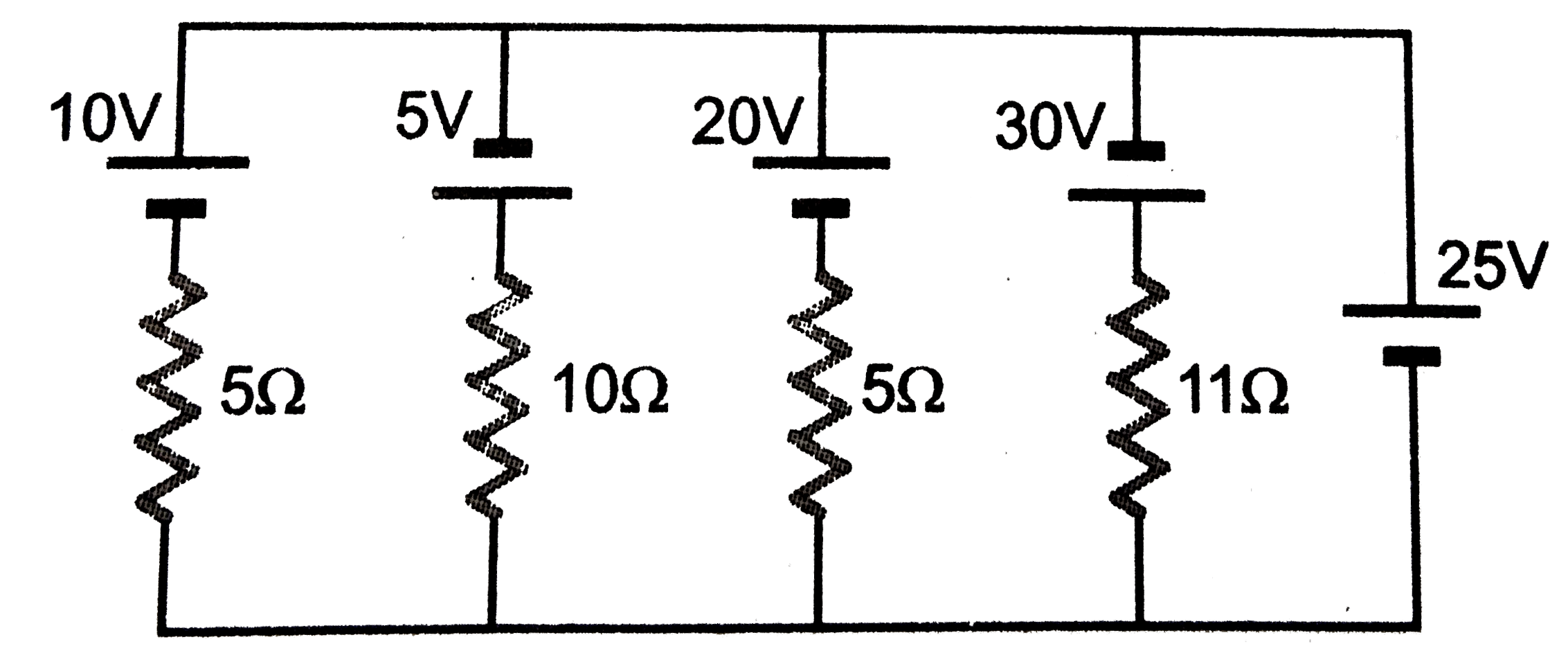
View SolutionIn the circuit shown in figure the current flowing through 25 V cell is
View SolutionA network of resistance cell and capacitor `C(=2 mu F)` is In steady state condition the change on `2 mu F` capacity is `Q` while `R` is unknown resistance value of `Q` and `R` are resistance
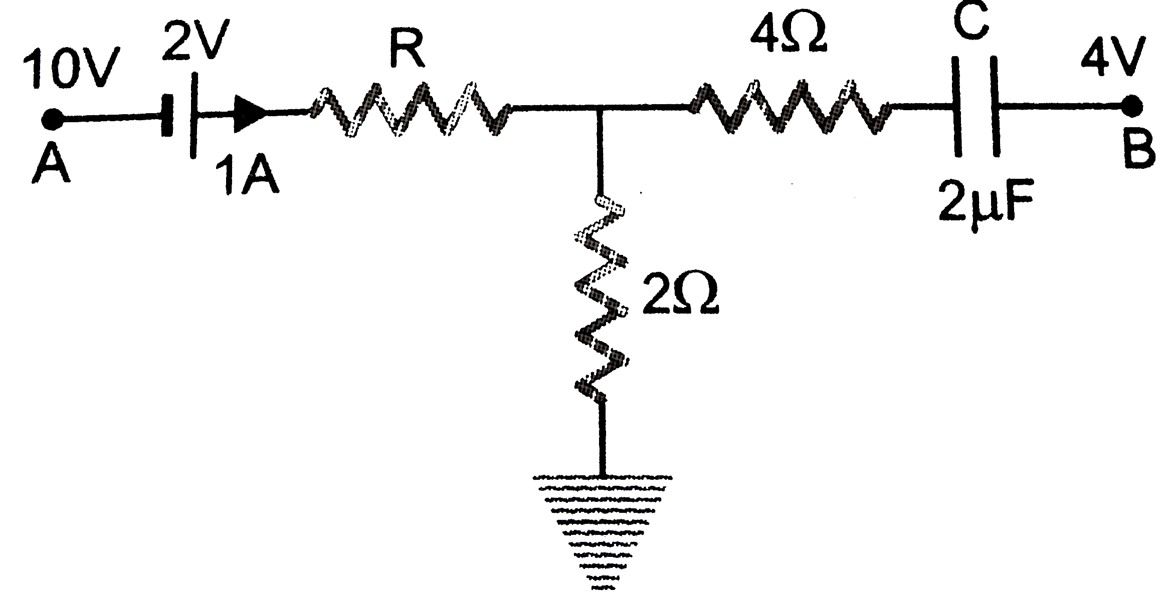
View SolutionIn the circuit shown in the figure, if potentail at point `A` is taken to be zero, the potential at point `B` is
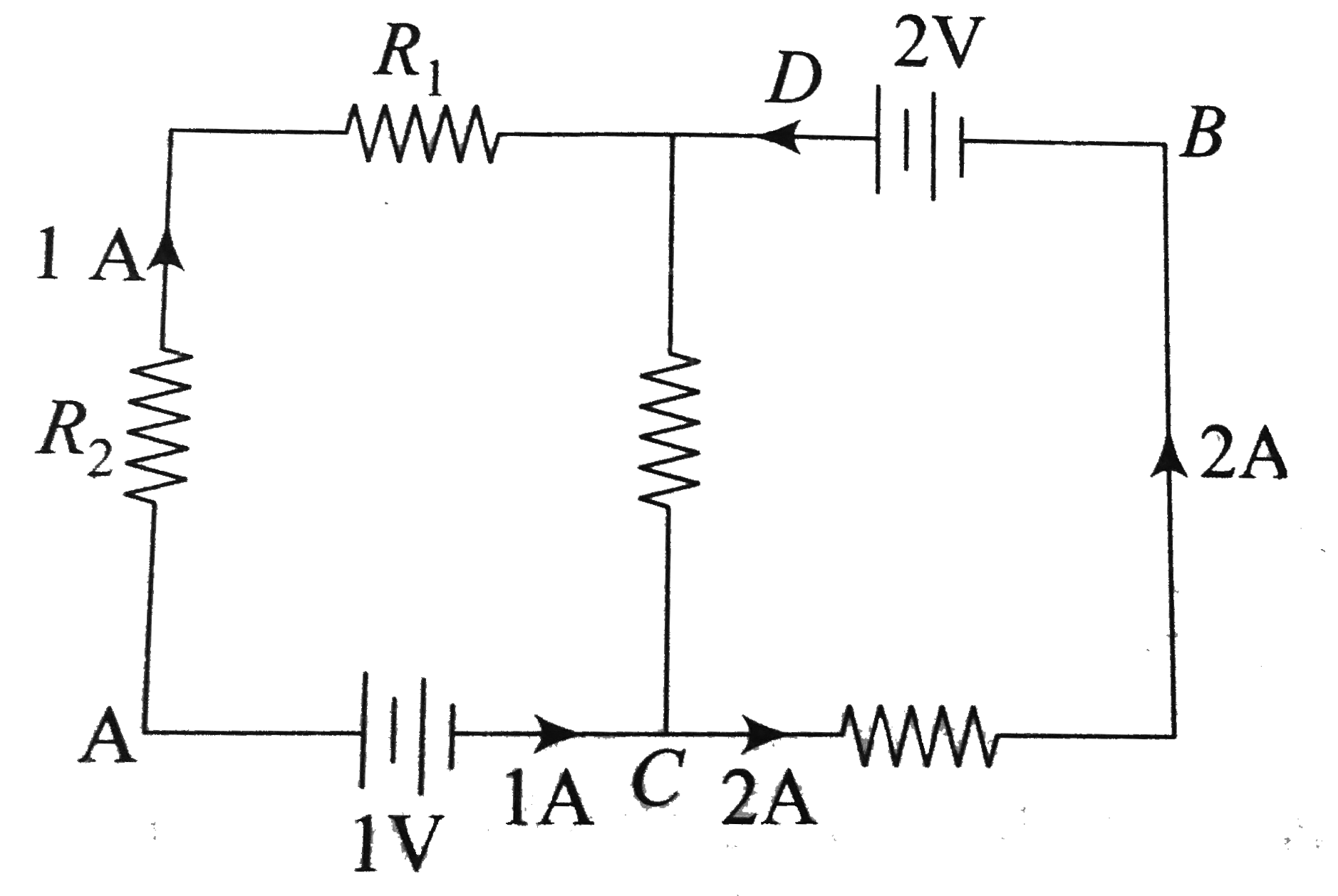
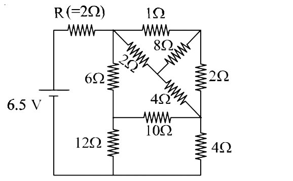
View SolutionIn the following circuit, the current through the resistor `R (=2Omega)` is I amperes. The value of I is
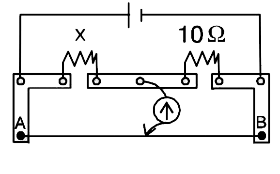
View SolutionA meter bridge is set up as shown, to determine an unknown resistance `X` using a standard 10 ohm resistor. The galvanometer shows null point when tapping -key is at 52 cm mark. The end-corrections are 1 cm and 2 cm respectively for the ends A and B. The determine value of `X` is
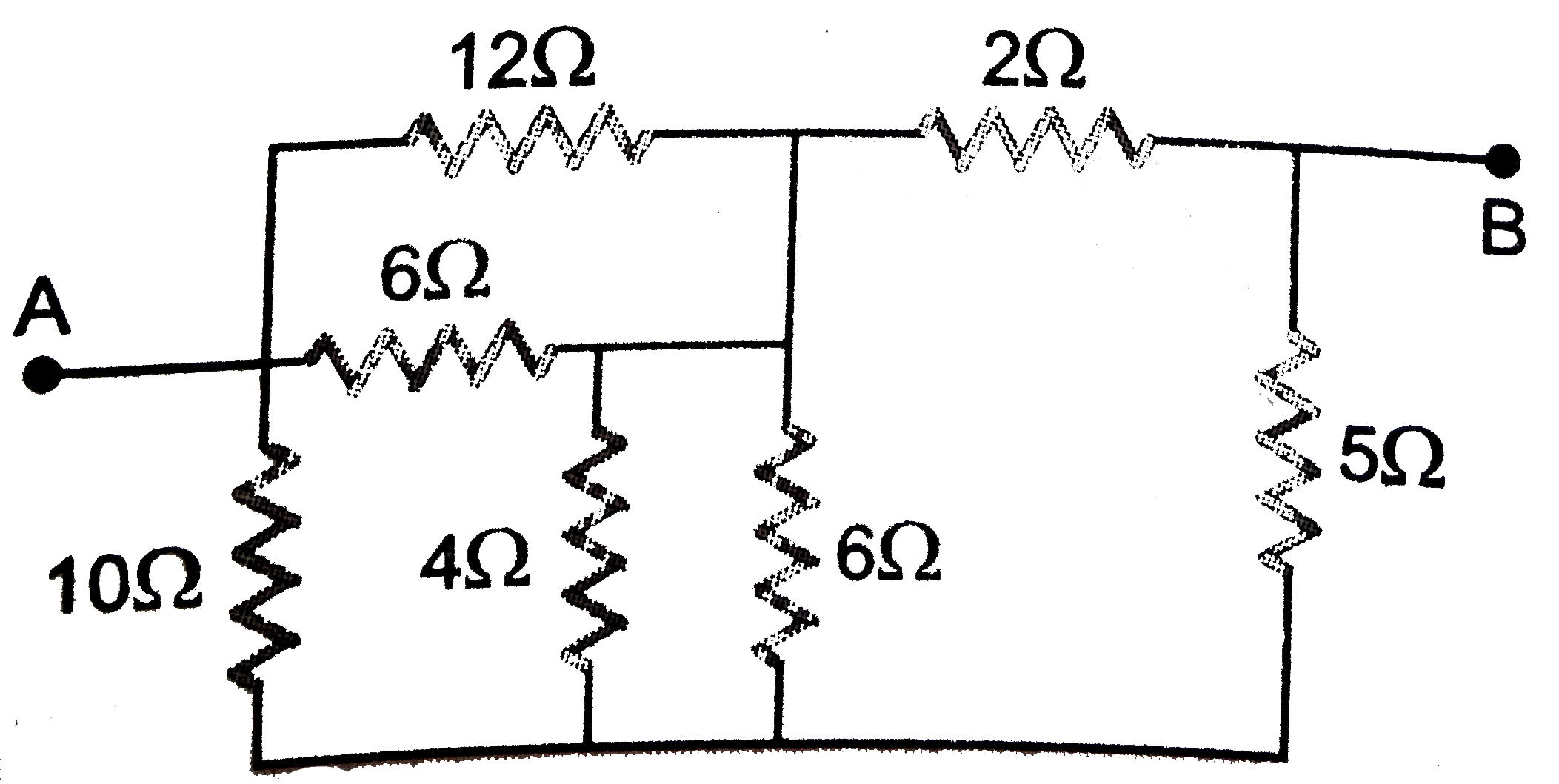
View SolutionSeven resistances are connected The equivalent resistance of this network in between point `A` and `B` is
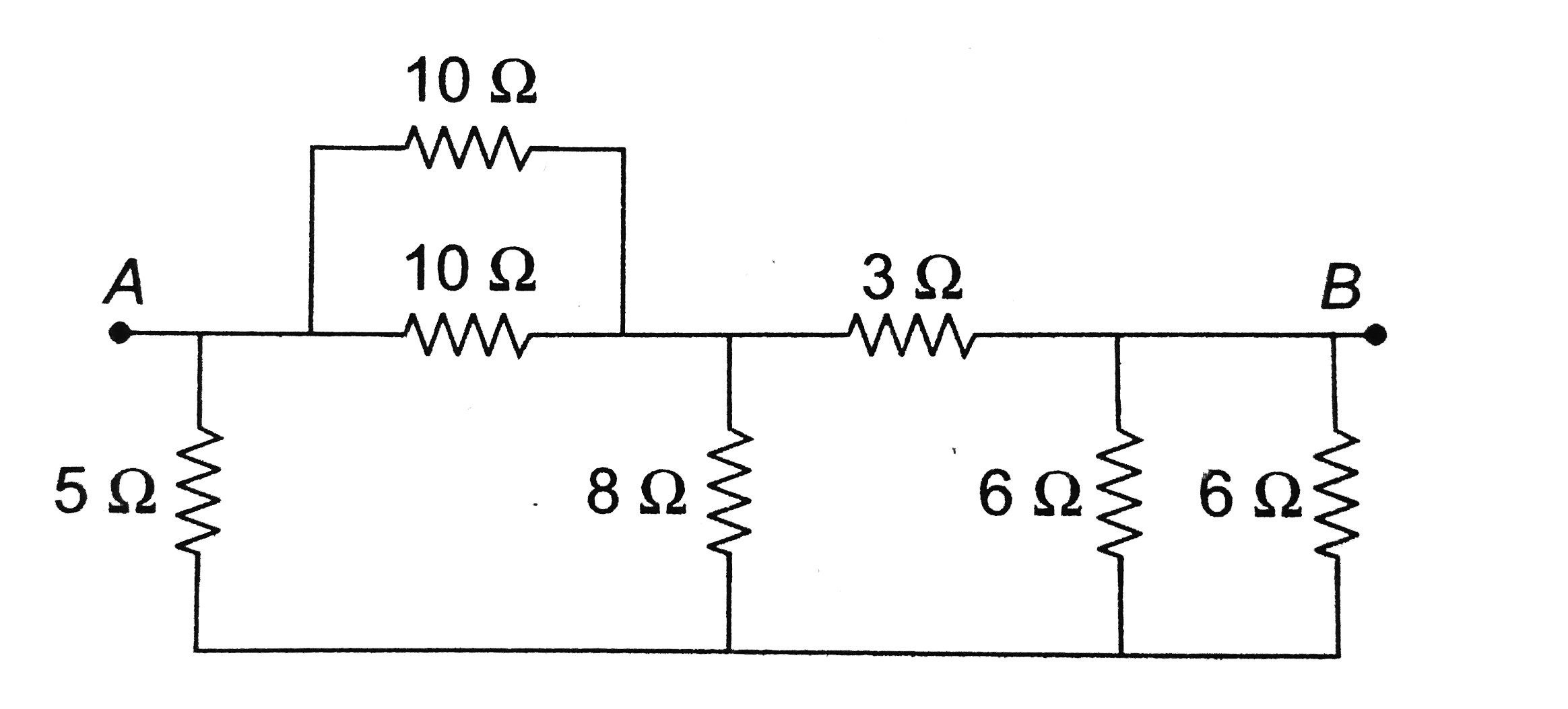
View SolutionSeven resistance are connected as shown in the firgure. The equivalent resistance between `A` and `B` is
View SolutionIn the circuit the resistance between `A` and `C` is
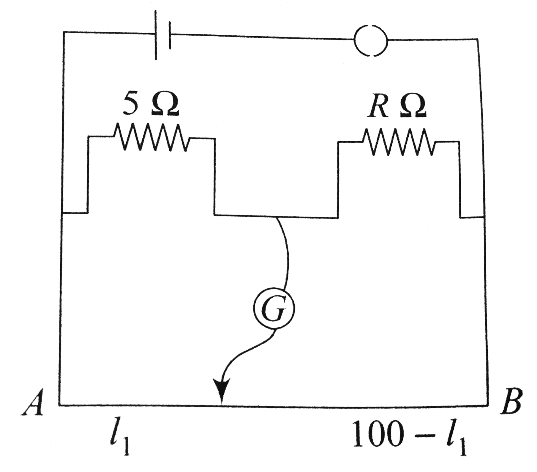
View SolutionThe resistance in the two arms of the meter bridge are `5 Omega` and `R Omega`, respectively. When the resistance `R` is shunted with an equal resistance, the new balance point is `1.6 l_(1)`.
The resistance `R` is
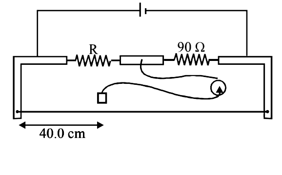
View SolutionDuring an experiment with a metre bridge, the galvanometer shows a null point when the jockey is pressed at `40.0 cm` using a standard resistance of `90 Omega`, as shown in the figure. The least count of the scale used in the metre bridge is 1mm. The unknown resistance is
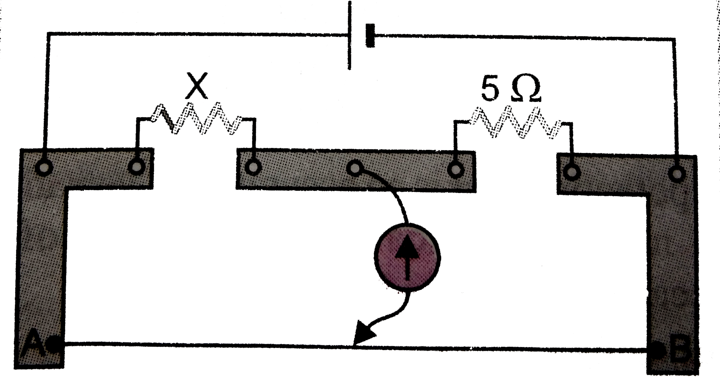
View SolutionA meter bridge is set up is as shown determine as unknown resistance `X` using a standerd `5 ohm` resistor The galvanometer shown nall point when topping key is at `44cm` mark The end corections see `1cm` and `2cm` respectively for the ends `A` and `B` The determine value of `X` is
View SolutionA resistance of `2 Omega` is connected across one gap of a meter bridge (the length of the wire is `100 cm` and an unknown resistance, greater than ` 2 Omega`, is connected across the other gap. When these resistance are interchanged, the balance point shifts by `20cm`. Neglecting any corrections, the unknown resistance is.
(a)` 3 Omega`
(b) `4 Omega`
( c) `5 Omega`
(d) `6 Omega`.
View SolutionA uniform wire of resistance `R` is stretched uniform in a times `R` is then cut to from five as The effective resistance between `A` and `C` is
View SolutionA potentiometer wire of Length `L` and a resistance `r` are connected in series with a battery of e.m.f. `E_(0)` and a resistance `r_(1)`. An unknown e.m.f. `E` is balanced at a length `l` of the potentiometer wire. The e.m.f. `E` will be given by :
View SolutionA potentiometer is an accurate and versatile devices to make electrical measurement of `E.M.F.` become the method involves
View SolutionA potentiometer wire has length `4 m` and resistance `8 Omega`. The resistance that must be connected in series with the wire and an accumulator of e.m.f. `2 V`, so as the get a potential gradient `1 mV` per cm` on the wire is
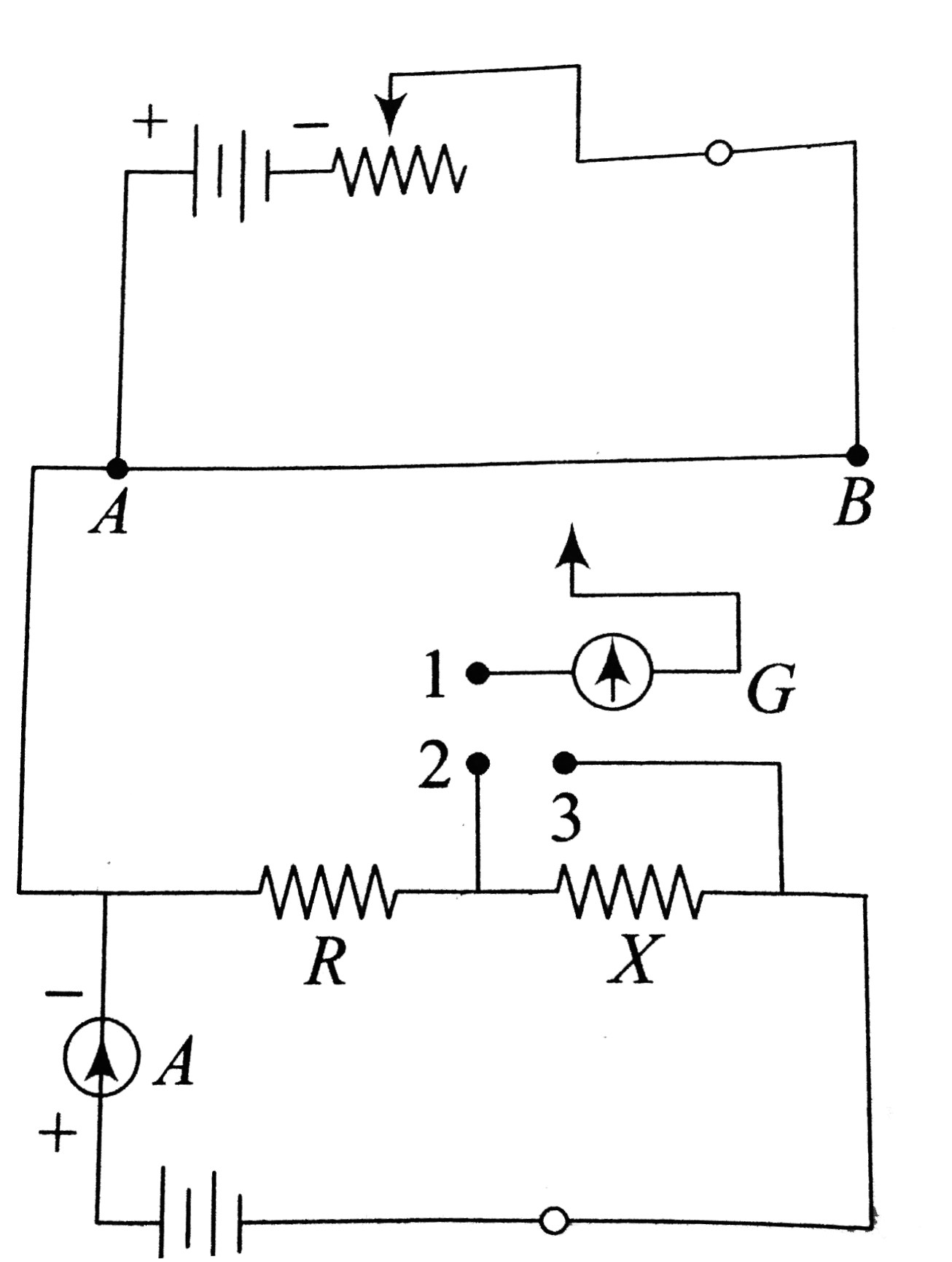
View SolutionA potentiometer circuit is setup as shown. The potential gradient across the potentiometer wire is `k "volt"//cm` and the ammeter present in the circuit reads. `1.0 A` When two-way key is switched off. The balance point, when the key between the terminals (i) 1 and 2 (ii) 1 and 3, is plugged in, are found to be at lengths `l_(2) cm` and `l_(2) cm` respectively. The magnitudes, of the resistors `R` and `X`, in ohm, are then, equal, respectively, to
View SolutionA potentiometer circuit has been setup for finding. The internal resistance of a given cell. The main battery used a negligible internal resistance. The potentiometer wire itsefl is `4 m` long. When the resistance, `R`, connected across the given cell, has value of
(i) Infinity `9.5 Omega`,
(ii) the 'balancing length' , on the potentiometer wire are found to be `3 m` and `2.85 m`, respectively.
The value of internal resistance of the cell is
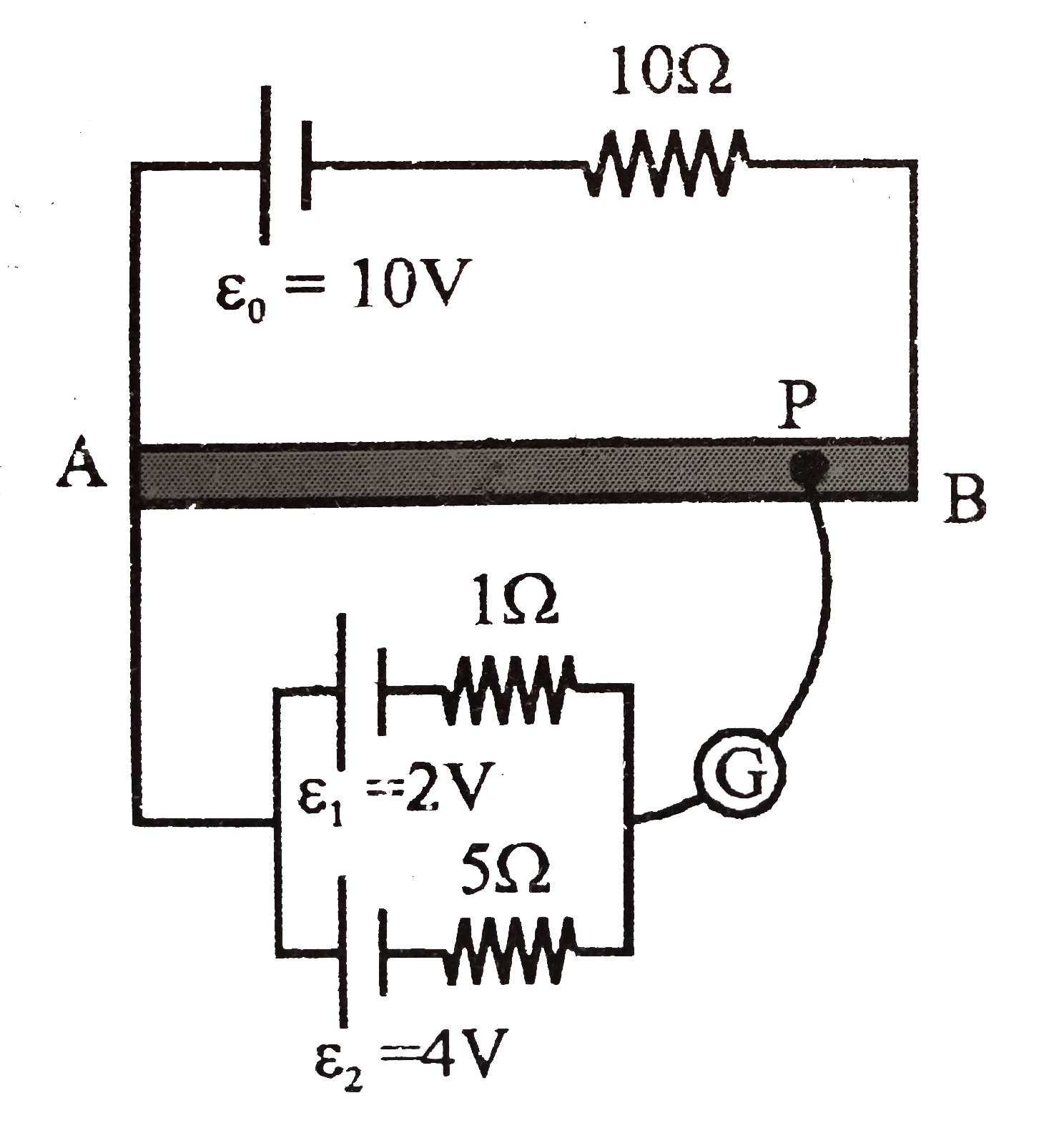
View SolutionA battery of emf `epsilon_0=10V` is connected across a `1m` long uniform wire having resistance `10Omega//m.` Two cells of emf `epsilon_1=2V` and `epsilon_2=4V` having internal resistance `1Omega` and `5Omega` respectively are connected as shown in the figure. If a galvanometer shows no deflection at the point `P`, find the distance of point `P` from the point `a`.
View SolutionA potentiometer wire is `100 cm` long hand a constant potential difference is maintained across it. Two cells are connected in series first to support one another and then in opposite direction. The balance points are obatined at `50 cm` and `10 cm` from the positive end of the wire in the two cases. The ratio of emfs is:
View SolutionThe charge flowing through a resistance `R` varies with time `t as Q = at - bt^(2)`. The total heat produced in `R` is
View SolutionIf voltage across a bulb rated 220 volt-100 watt drops by `2.5 %` of its value, the percentage of the rated value by which the power would decrease is
View SolutionA `1^(@) C` rise in temperature is observed in a conductor by passing a certain current . If the current is doubled , then the rise in temperature is approximately
View SolutionMasses fo three are in the ratio `1:3:5` their lengths are in the ratio `5:3:1` when they are connected in series to an external source, the amounts of heats produced in them are in the ratio
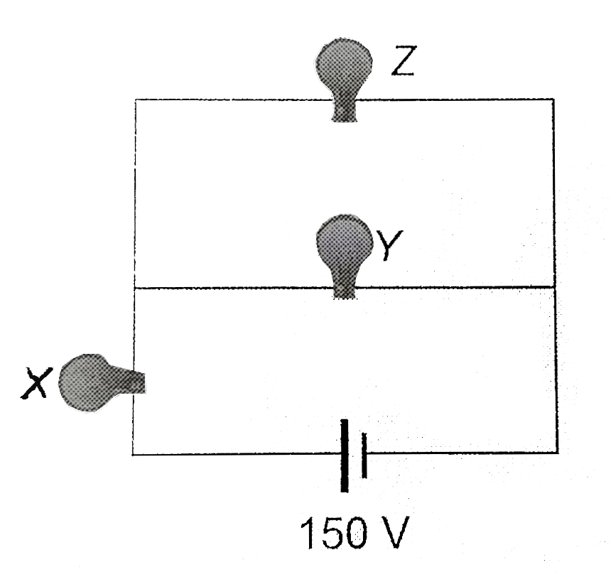
View SolutionThree `100W, 150V` lamps are connected across a `150V power line as shown. Find (a) Voltage across each lamp and (b) total power dissipated in three bulbs.
View SolutionIf two bulbs of `25 W and 100 W` rated at `220 V` are connected in series across a `440 V` supply, will both the bulbs fuse ? If not which one ?
View SolutionIn the circuit shown in fig the heat produced in the 5 ohm resistor due to the current flowing through it is 10 calories per second.
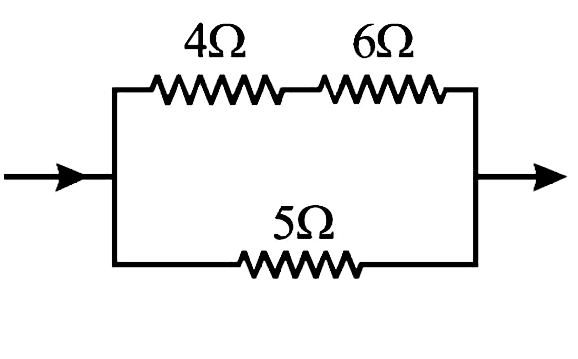
The heat generated in the 4 ohms resistor is
View SolutionHow many lamps each of `50W`and `100W`can be connected in parallel across a `120V` battery of internal resistance `10 Omega` so the each glows to full power ?
View Solution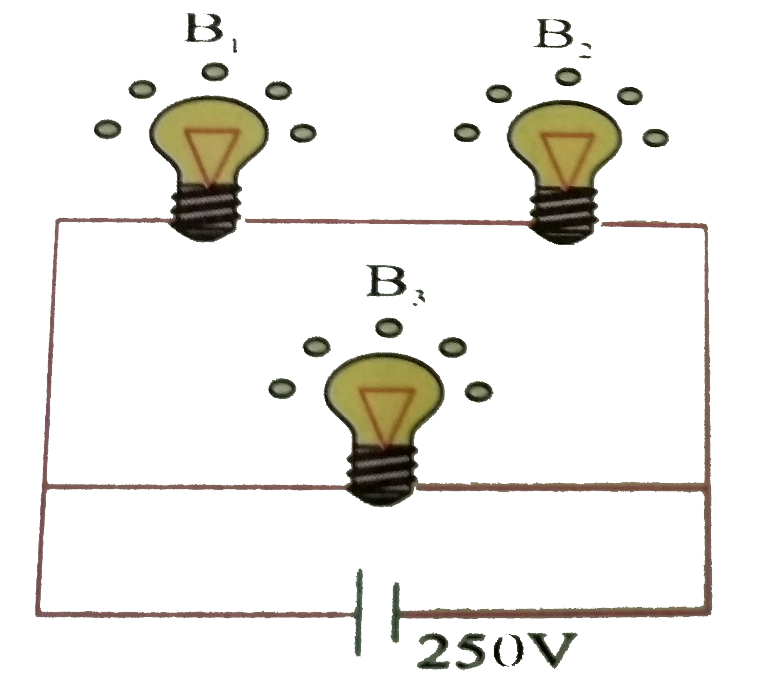
A 100 W bulb `B_(1)` and two 60 W bulbs `B_(2)` and `B_(3)`, are connected to a 250V source, as shown in the figure now `W_(1),W_(2)` and `W_(3)` are the output powers of the bulbs `B_(1),B_(2)` and `B_(3)` respectively then
View SolutionIncandescent bulbs are designed by keeping in mind that the resistance of their filament increases with the increase in temperature. If at room temperature, `100W, 60W and 40W` bulbs have filament resistances `R_(100), R_(60) and R_(40)`, respectively, the relation between these resistances is
View SolutionIf power dissipated in the `9 Omega` resistor in the resistor shown is `36 W`, the potential difference across the `2 Omega` resistor is
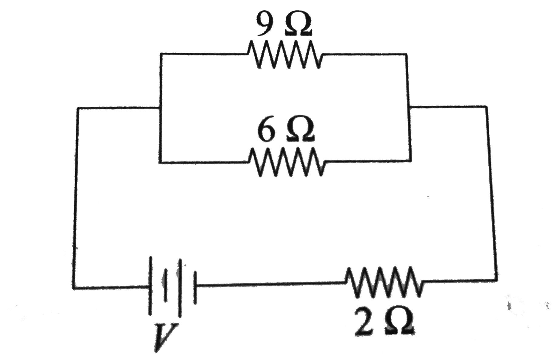
View SolutionThe power dissipated in the circuit shown in the is 30 watts. The value of `R` is
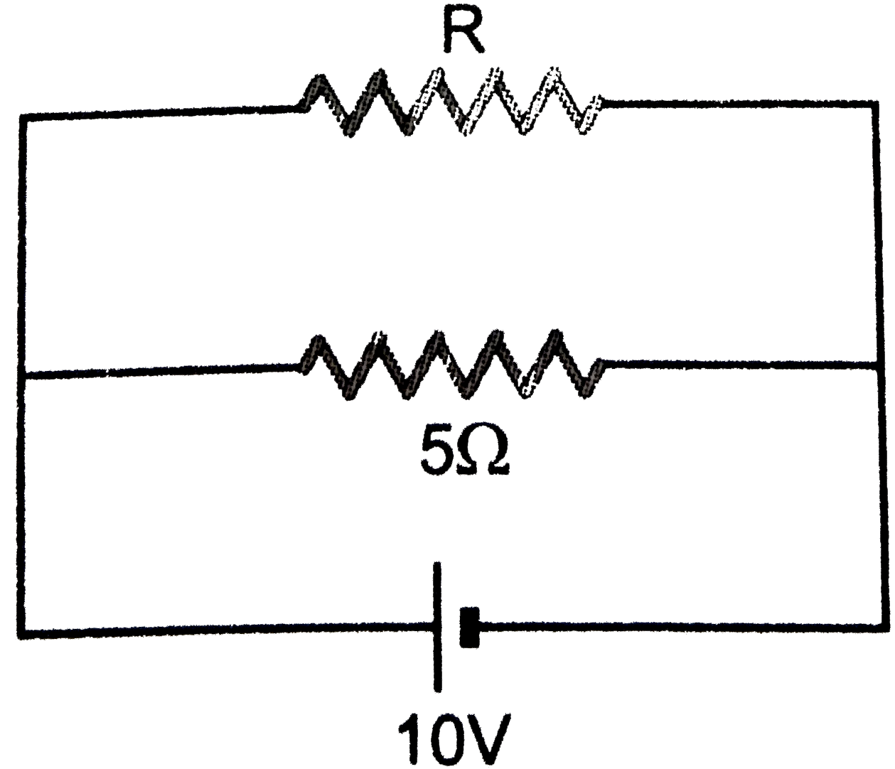
View SolutionThe supply voltage to room is 120 V. The resistance of the lead wires is `6Omega`. A 60 W bulb is already switched on. What is the decrease of voltage across the bulb, when a 240 W heater is switched on in parallel to the bulb?
View SolutionA d.c. voltage with appreciable ripple expressed as `V = V_(1) + V_(2) cos omega t ` is applied is a resistor The amount of heat generated per second is given by
View SolutionA heater boils `1kg` water in time `t_(1)` and another heater bolis the same water in time `t_(2)`. If both the heater are connected in parallel, the combination will bolt the water in time
View SolutionIn the above question , if the heaters are connected in series , the combination will bolt the same water in time
View SolutionA time wire with a circuit-sectional radius of `0.02mm` blows with a current of `5` ampere for what current another fuse wire made from the same material with cross-section radius of `0.04` mm will blow?
View SolutionA resistance of `4 Omega ` is connected across a cell Then it is replaced by another resistance of `1 Omega` it is found the power dissipeted in resistance in both the is `16` walt Then
View SolutionThe charge flowing in a conductor varies with times as `Q = at - bt^2.` Then, the current
View SolutionTwo heaters designed for the same voltage `V` have different power ratings. When connected individually across as source of voltage` V`, they produce `H` amount of heat each in time `t_1` and `t_2` respectively. When used together acros the same source, they produce H amount of heat in time t
View SolutionIn the circuit shown in fig. some potential difference is applied between A and B. The equivalent resistance between A and B is R.

View SolutionTwo bulbs consume same energy when operated at `200 V and 300 V` , respectively . When these bulbs are connected in series across a dc source of `500 V`, then
View SolutionFor the circuit shown in figure
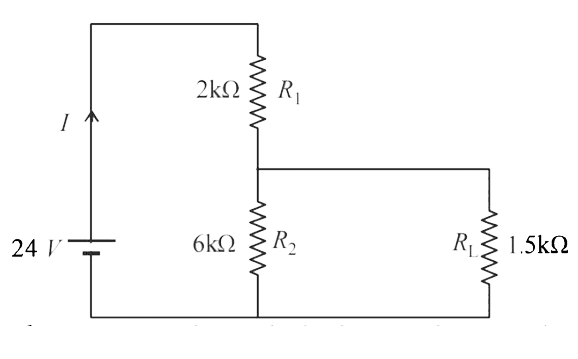
View SolutionFor the circuit
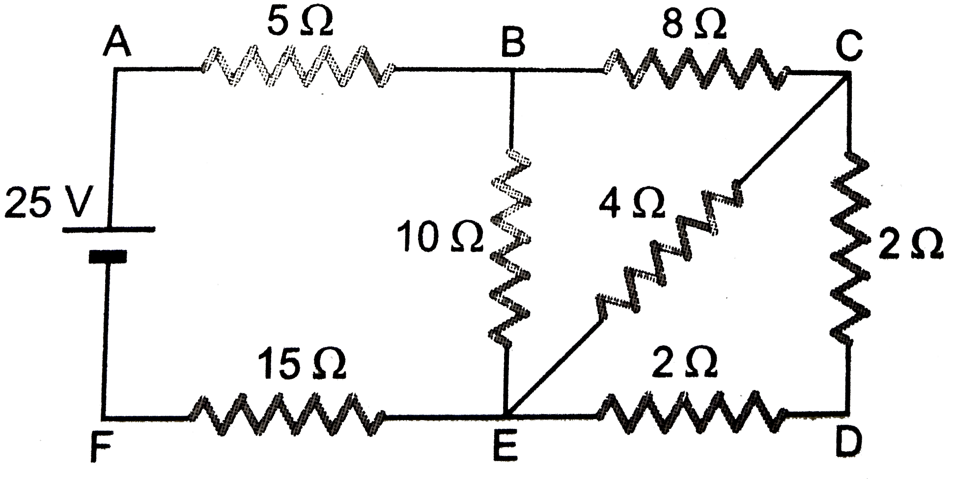
View SolutionHeater of an electric kettle is made of a wire of length L and diameter d. It takes 4 minutes to raise the temperature of 0.5 kg water by 40K. This heater is replaced by a new heater having two wires of the same material, each of length L and diameter 2d. The way these wires are connected is given in the options. How much time in minutes will it take to raise the temperature of the same amount of water by 40 K?
View Solution
Exercise questions and complete solutions for chapter CURRENT ELECTRICITY of PRADEEP PHYSICS (HINGLISH) of Class 12