level-2 from ARIHANT PHYSICS (HINGLISH) ALTERNATING CURRENT for Class 12
| Class 12 | PHYSICS |
| Chapter | ALTERNATING CURRENT |
| ARIHANT PHYSICS (HINGLISH) | level-2 |
| Medium | English |
| Academic Year | 2023-2024 |
Question 5
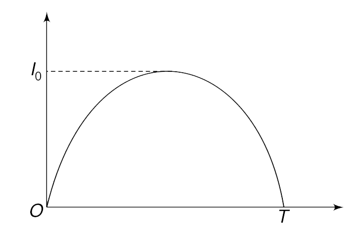
The graph given here represents an idealized sinusoidal current flow between a cloud at a height of 1 km and the earth, during a lightning discharge. Value of I0 is 157 kA and T = 0.2 ms. Assume that discharge happens when the electric field in the air between the cloud and the earth becomes equal to the breakdown field of air i.e., E0=3×10⁶V/m
(a) Calculate the total charge flow due to lightning.
(b) Calculate the average current between the cloud and the earth during the lightning.
(c) Assume that the entire charge on the cloud is released during the lightning and estimate the capacitance of the cloud – Earth system.
 View Solution
Question 6
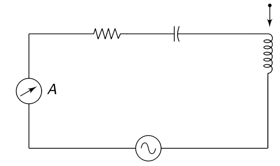
In the circuit shown, the frequency of the source is adjusted so that the reading of the ac ammeter is maximum. The inductor shown is a short coil in vertical orientation. A steel ball is dropped through the coil. How is the reading of ammeter affected when the ball enters the coil?
 View Solution
Question 7
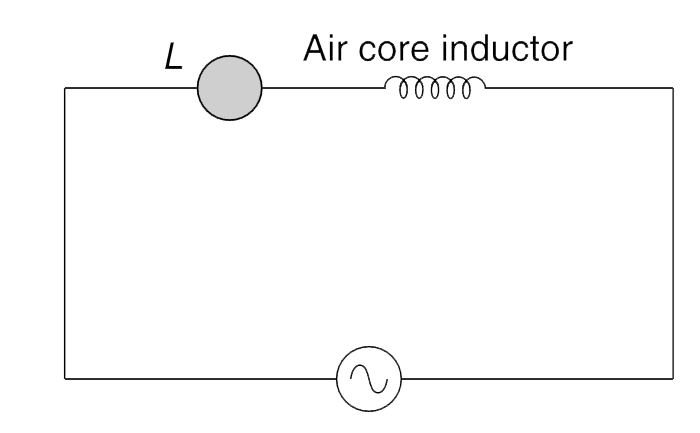
A lamp L is connected to an ac source along with an air core inductor as shown in the Figure. How is the brilliance of the lamp affected if core made of following material is inserted inside the inductor? (a) Iron (b) Copper (c) Iron sheets pasted together with insulation in between [laminated Iron core] In which case the lamp will be least bright?
 View Solution
Question 11
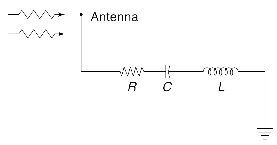
A FM radio receiver has a series LCR circuit with L = 1 μH, and R = 100 Ω. The antenna receives radio waves and induces a sinusoidally alternating emf of ampli- tude 10 μV. The induced voltage is fed to the series LCR circuit. The capacitance in the circuit is adjusted to a value of C = 2 pF.
(a) Find the frequency of radio wave to which the radio will tune to.
(b) Find the rms current in the circuit.
(c) Find quality factor of the resonance.
 View Solution
Question 12
In the circuit shown in Figure, the source has a rating of 15 V, 100 Hz. The resistance R is 3 Ω and the reactance of the capacitor is 4 Ω. It is known that the box certainly contains one or more element (resistance, capacitance or inductance). Which element/s are present inside the box?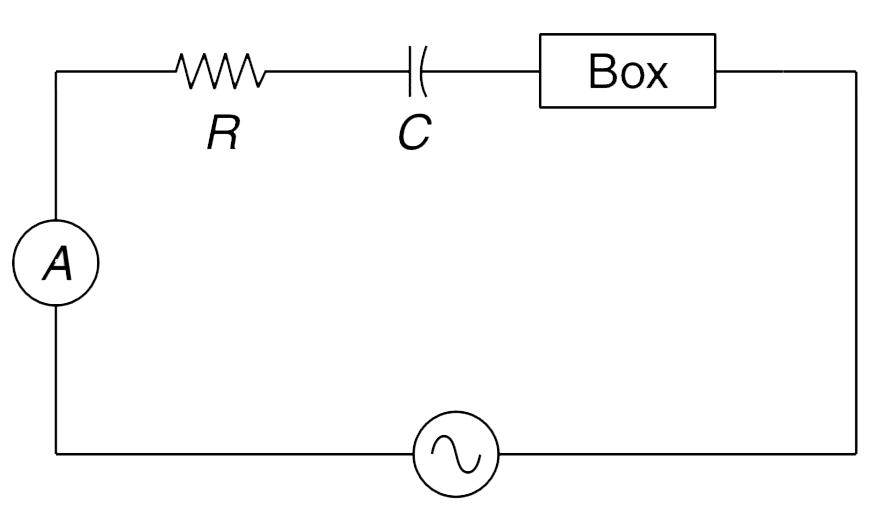 View Solution
Question 13
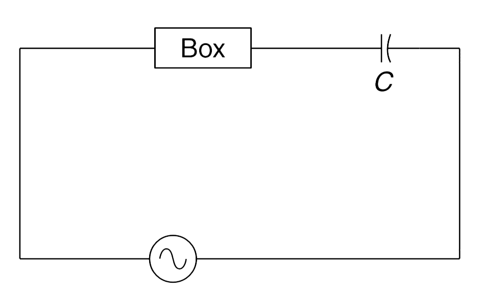
A box has a large electric circuit inside it. When it was connected to an ac generator it was found that it was putting a lot of load on the generator and the power factor of the box was 1√2. A capacitor of capacitance C was connected in series with the box and the power factor of the circuit became equal to the ideal value. Find the impedance of the box. The generator has an angular frequency ofω.
 View Solution
Question 16
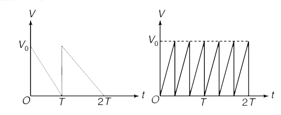
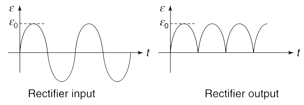
A transformer with 20 turns in its secondary coil is used to step down the input 220 V ac emf. The output of the transformer is fed to a rectifier circuit which convents the ac input into dc output. The input and output of rectifier are as shown in Figure (there is no change in peak voltage). The rectifier output has an average emf of 8.98 volt. Calculate the number of turns in the primary coil of the transformer.
 View Solution
Question 17
Two boys are holding a wire, standing 4 m apart. The wire sags in the shape of a circular arc with a sag of 1.0 m. The students rotate the wire about the horizontal line connecting their hands, as if they were playing jump rope. The boys rotate the wire at a speed of 4 revolutions per second. The earth’s magnetic field at the location is4×10–5 T. Calculate the rms value of emf developed between the ends of the wire. Assume that the shape of the wire is maintained as it is rotated. View SolutionQuestion 18
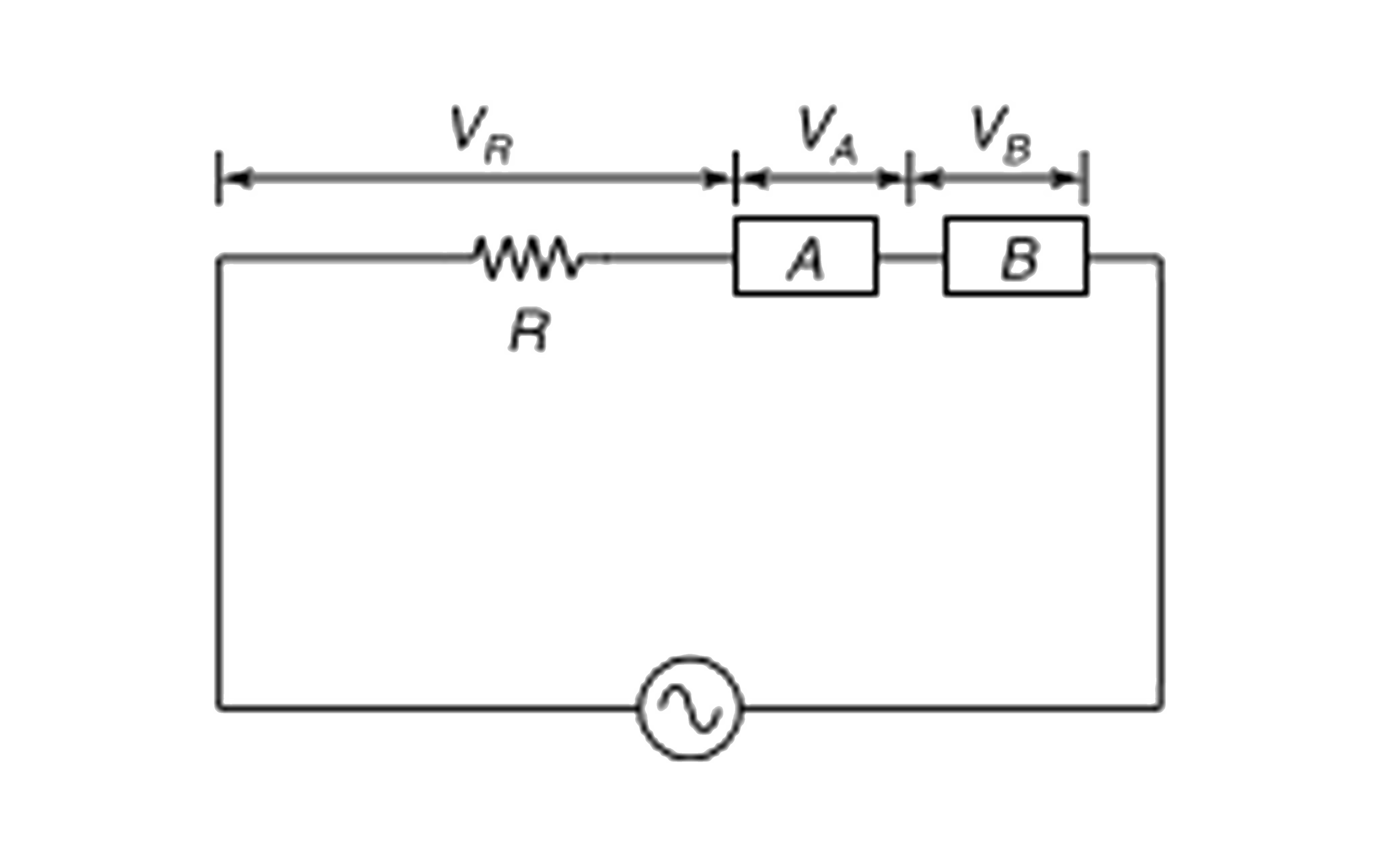
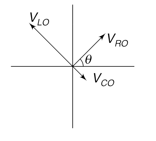
In a series LCR circuit the phasors corresponding to voltage across resistance, capacitor and inductor at an instant are as shown in the Figure and have amplitudes ofVRO=4volt,VCO=3volt,andVLO=6volt
(a) Is the source frequency larger than or lesser than the resonance frequency? Does the current (I) lead or lag the source voltage?
(b) Find the voltage amplitude of the source.
(c) If VR phasor makes θ=53∘ at time t = 0, write the source voltage as function of time. Take angular frequency of the source to be ω[sin53∘=45]
 View Solution
Question 19
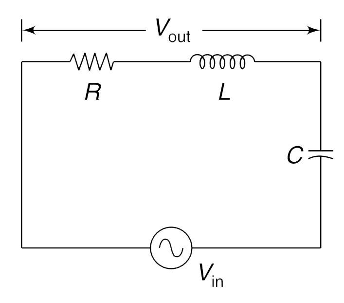
A series LCR circuit having resistance R, capacitance C and inductance L has a voltage source of angular frequency ω and voltage V∈. Output voltage (Vout) is taken as voltage across the resistor and inductor combined.
(a) Find η=VoutVin
(b) Find η in the limit of large ω(ω>>1RC,1√LC,RL)
(C )Find η in the limit of smallω(ω>>1RC,1√LC,RL)
 View Solution
Question 20
In a series LCR circuit, the frequencies at which the current amplitude is1√2mes the current amplitude at resonance aref1andf2(>f1). Find the frequency bandwidth of resonance which is defined as Δf=f2−f1. Express your answer in terms of R and L. Assume that resonance frequency f0>>ΔfView SolutionQuestion 21
A series RLC circuit is in resonance with a source of frequency ω0 = 10 MHz. The current amplitude in the circuit is I0. It was found that when a different source of frequencyω=ω0+Δω[Δω=10KHz] was used the current amplitude in the circuit was only 1% of I0. Find the inductance in the circuit if it is known that resistance in the circuit is R = 0.314 Ω. View SolutionQuestion 22
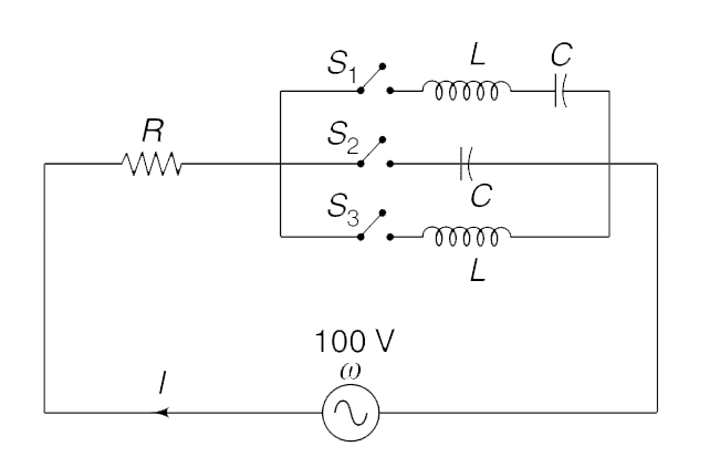
In the circuit shown in the figure, one of the three switches is kept closed and other two are open. The value of resistance is R = 20 Ω. When the angular frequency(w) of the 100 V source is adjusted to 500 rad/s, 1000 rad/s and 2000 rad/s it was found that the current I was 4A, 5A and 4A respectively.
(a) Which switch id closed ?(S1,S2orS3)
(b)Find the value of L and C.
 View Solution
Question 23
A village with a demand of 800 kW electric power at 220 V is located 30 km from an electric plant generating power at 440 V. The resistance of the two wire line carrying power is 0.25 Ω/km. The village gets power from the line through a 4000 V – 220 V step down transformer at a sub-station in the village. Assume negligible power loss in the transformers
(a) Estimate the power loss in form of heat in the transmission line.
(b) How much power must the plant supply?
(c) What is the input and output voltage of step-up transformer at the plant ?
(d) What difference will it make if the village receives power through a 40,000 V – 220 V step down transformer View SolutionQuestion 24
A resistance R and a capacitor having capaci- tance C are connected to an alternating source having emf v=V0sin(ωt).It is given that ω=1√3RC
(a) Plot the variation of power supplied by the source as a function of time. Mark the maximum and minimum values of power in the graph.
(b) How does the plot change if capacitor is removed and only R remains connected to the source?
(c) Plot the graph when only C remains connected to source and R is removed.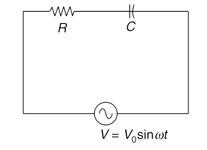 View Solution

