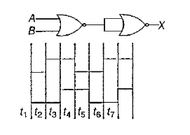
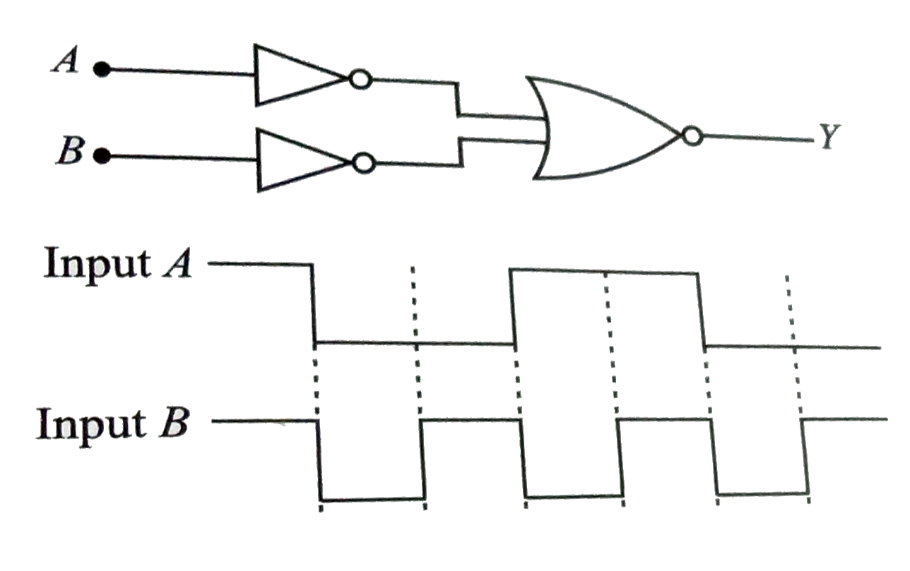
Draw the output waveform at X using the given inputs A and B for the logic circuit shown below. Also identify the logic operation performed by this circuit.
That is logic operation is OR
Related Solutions
Draw the output waveform at X, using the given inputs, A and B for the logic circuit shown below. Also, identify the logic operation performed by this circuit.
View SolutionDraw the output waveformed at X, using the given inputs A and B for the logic circuit shows below. Also, identify the logic operation performed by this circuit.

View SolutionDraw the output waveform X, using the given inputs A and B for the logic circuit shows below. Also, identify the logic operation performed by this circuit.

View SolutionDraw the output waveformed at X, using the given inputs A and B for the logic circuit shows below. Also, identify the logic operation performed by this circuit.

View SolutionDraw the output waveform X, using the given inputs A and B for the logic circuit shows below. Also, identify the logic operation performed by this circuit.

View SolutionDrawn the output waveform at X, using thye given inputs A and B for the logic circuit shown in Fig. Also identify the logic operation performed by this circuit.

View SolutionUsing the wave forms of the input A and B, draw the output waveform of the given logic circuit . Identify the logic gate obtained . Write also the truth table.
View SolutionUsing the wave forms of the input A and B, draw the output waveform of the given logic circuit . Identify the logic gate obtained . Write also the truth table.

View SolutionThe logic circuit shown below has the input waveform 'A' and 'B' as shown . Pick out the correct output waveform .
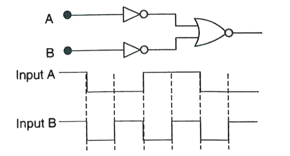
output is :
View SolutionThe logic circuit shown below has the input waveform 'A' and 'B' as shown. Pick out the correct output waveform
_E01_490_Q01.png)
Output is :-
View SolutionThe logic circuit shown below has the input waveform 'A' and 'B' as shown. Pick out the correct output waveform Output is :-
View SolutionThe logic circuit shown belows has the input waveforms and as shown. Pick out the correct output waveform
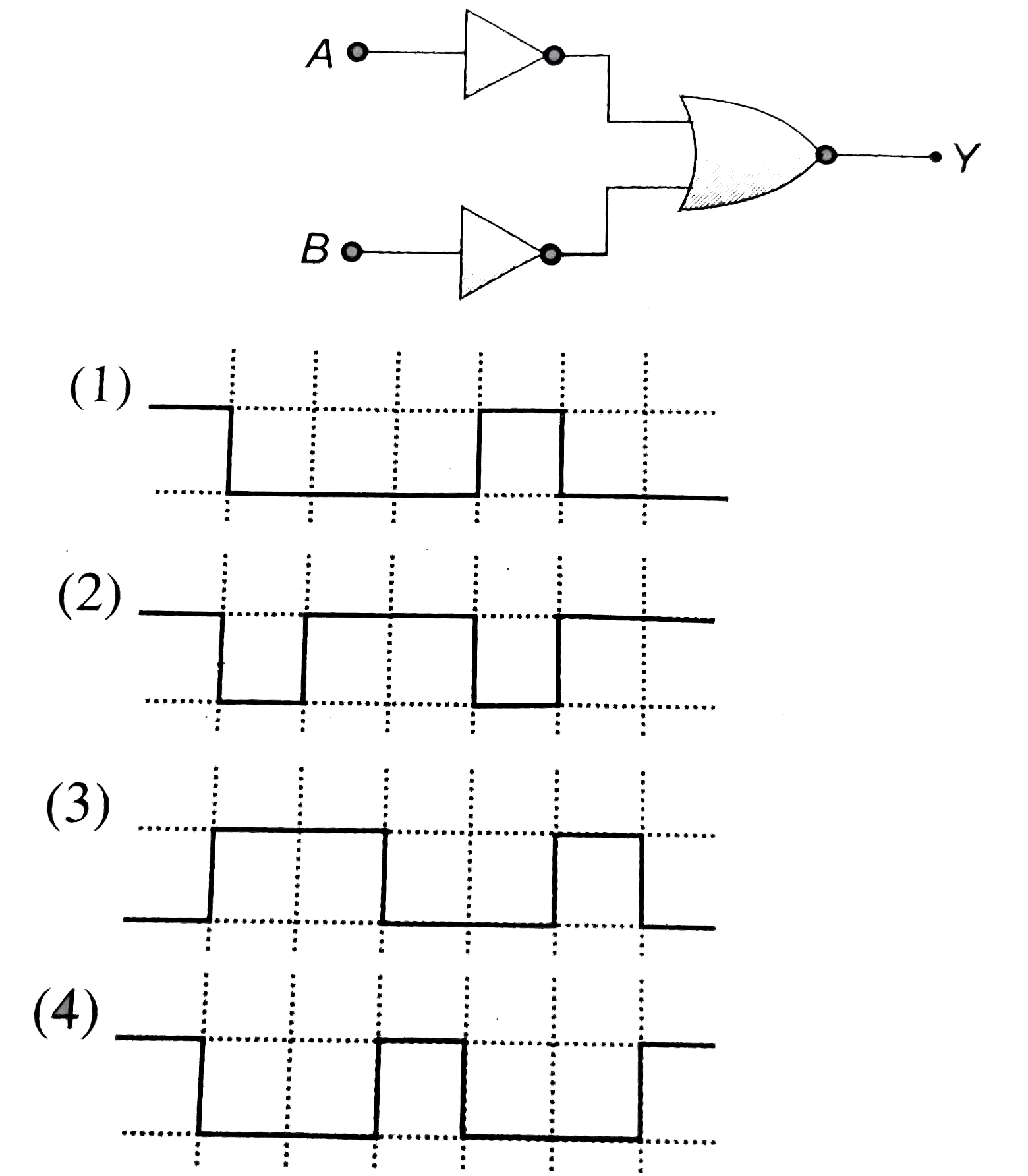
View SolutionThe logic circuit shown below has the input waveforms 'A' and 'B' as shown. Pick out the correct output waveform
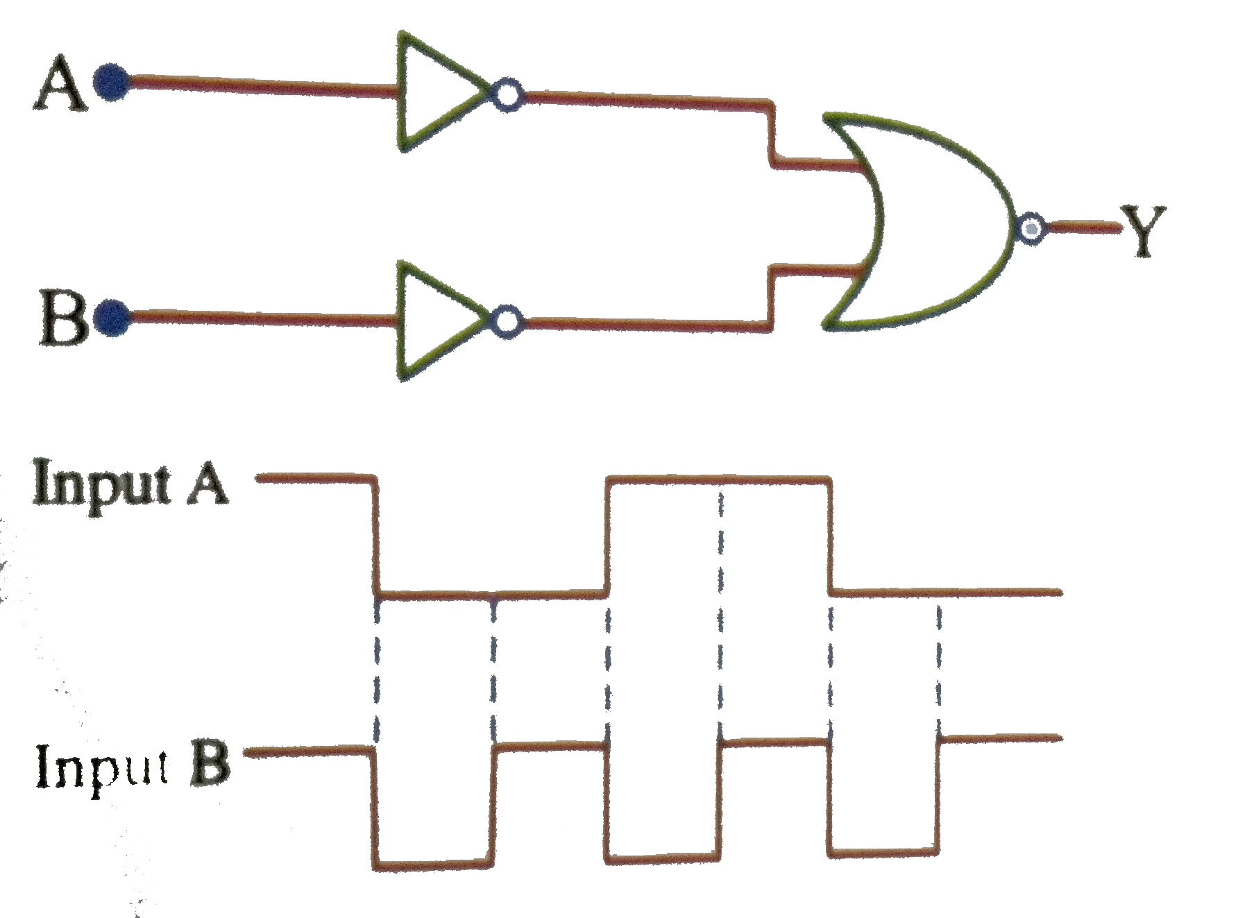 .
.
View SolutionThe logic circuit shown below has the inputs waveforms A and B as shown. Pick out the correct output waveform.
View SolutionThe logic circuit shown below has the input waveforms 'A' and 'B' as shown. Pick out the correct output waveform .
View SolutionThe logic circuit shown below has the input waveforms 'A' and 'B' as shown. Pick out the current output waveform.
View SolutionThe logic circuit shown below has the inputs waveforms A and B as shown. Pick out the correct output waveform.
View SolutionThe logic circuit shown below has the input waveforms ‘A’ and ‘B’ as shown. Pick out the correct output waveform
View Solution(a) In the figure given below the input waveform is converted into the output waveform by a device 'X'. Name the device and draw its circuit diagram.

(b) Identify the logic gate represented by the circuit as shown and write its truth table.

View SolutionThe following shows a logic gate circuit with two inputs A and B and the output C. The voltage waveforms of A, B and C are as shown below.
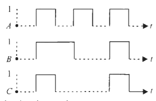
The logic circuit gate is
View Solution