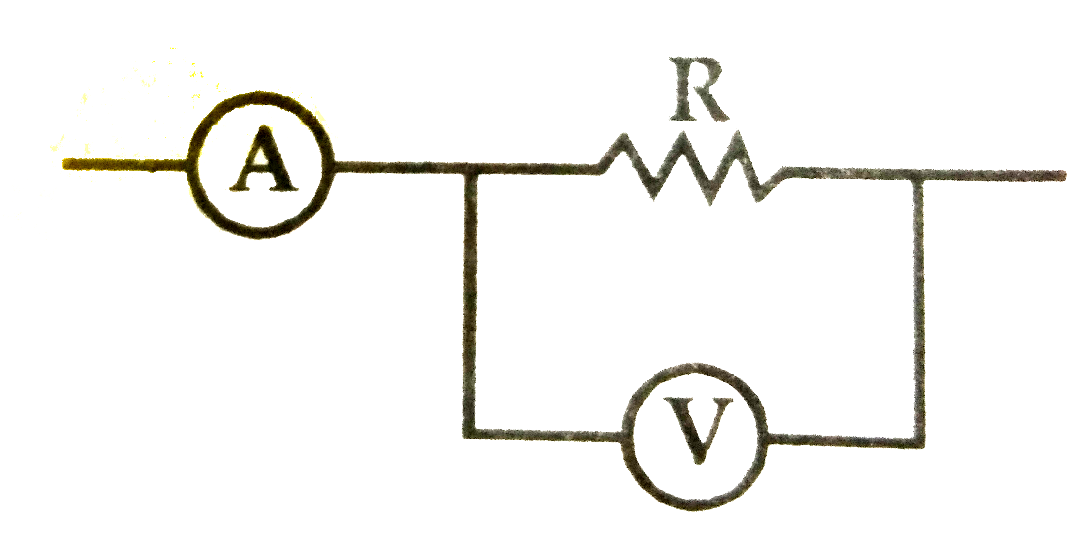
In the circuit shown in figure,an ideal ammeter and an ideal voltmeter are used.When the key is open,the voltmeter reads "1.53V".When the key is ,the ammeter reads "1.0A" and the voltmeter reads "1.03V" .The resistance "R" is
Step by step video & image solution for In the circuit shown in figure,an ideal ammeter and an ideal voltmeter are used.When the key is open,the voltmeter reads "1.53V".When the key is ,the ammeter reads "1.0A" and the voltmeter reads "1.03V" .The resistance "R" is by Physics experts to help you in doubts & scoring excellent marks in Class 11 exams.
Similar Questions
In the circuit shown in figure,an ideal ammeter and an ideal voltmeter are used.When the key is open,the voltmeter reads "1.53V".When the key is ,the ammeter reads "1.0A" and the voltmeter reads "1.03V" .The resistance "R" is
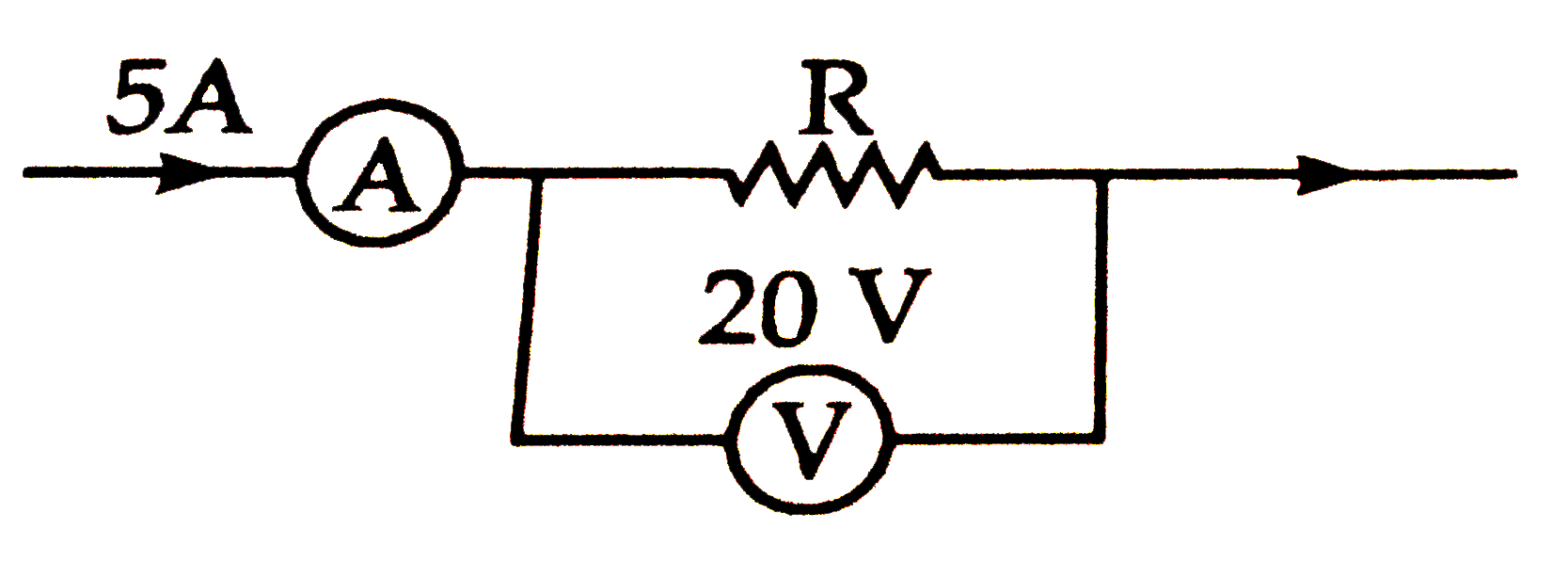
View SolutionIn the adjacent circuit the ammeter reads 5.0 A and voltmeter reads 20V. The value of resistance R is
 View Solution
Knowledge Check
- Question 1 - Select One
In the circuit shown in Fig. 6.50, an idel ammeter and an ideal voltmeter are used. Whan the key is open, the voltmeter reads 1.53V. When the key is closed, the ammeter reads 1.0A and the voltmeter reads 1.03V. The resistance R is
 A0.5ΩB1.03ΩC1.53ΩD1.53Ω
 - Question 2 - Select One
In the circuit shown here, the readings of the ammeter and voltmeter are
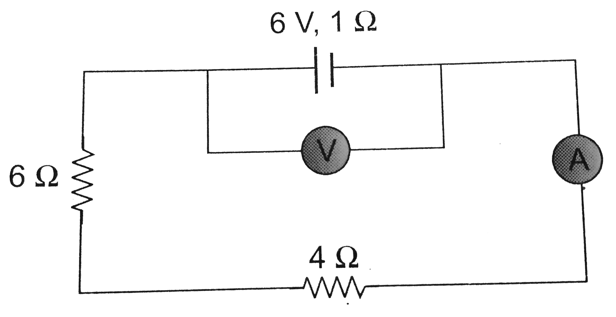 A6A,60VB0.6A,6VC6/11A,60/11VD11/6A,11/60V
 - Question 3 - Select One
In the circuit shown in figure, what will be the readings of voltmeter and ammeter?
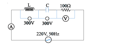 A800 V, 2 AB220 V, 2.2 AC300 V, 2 AD100 V, 2 A
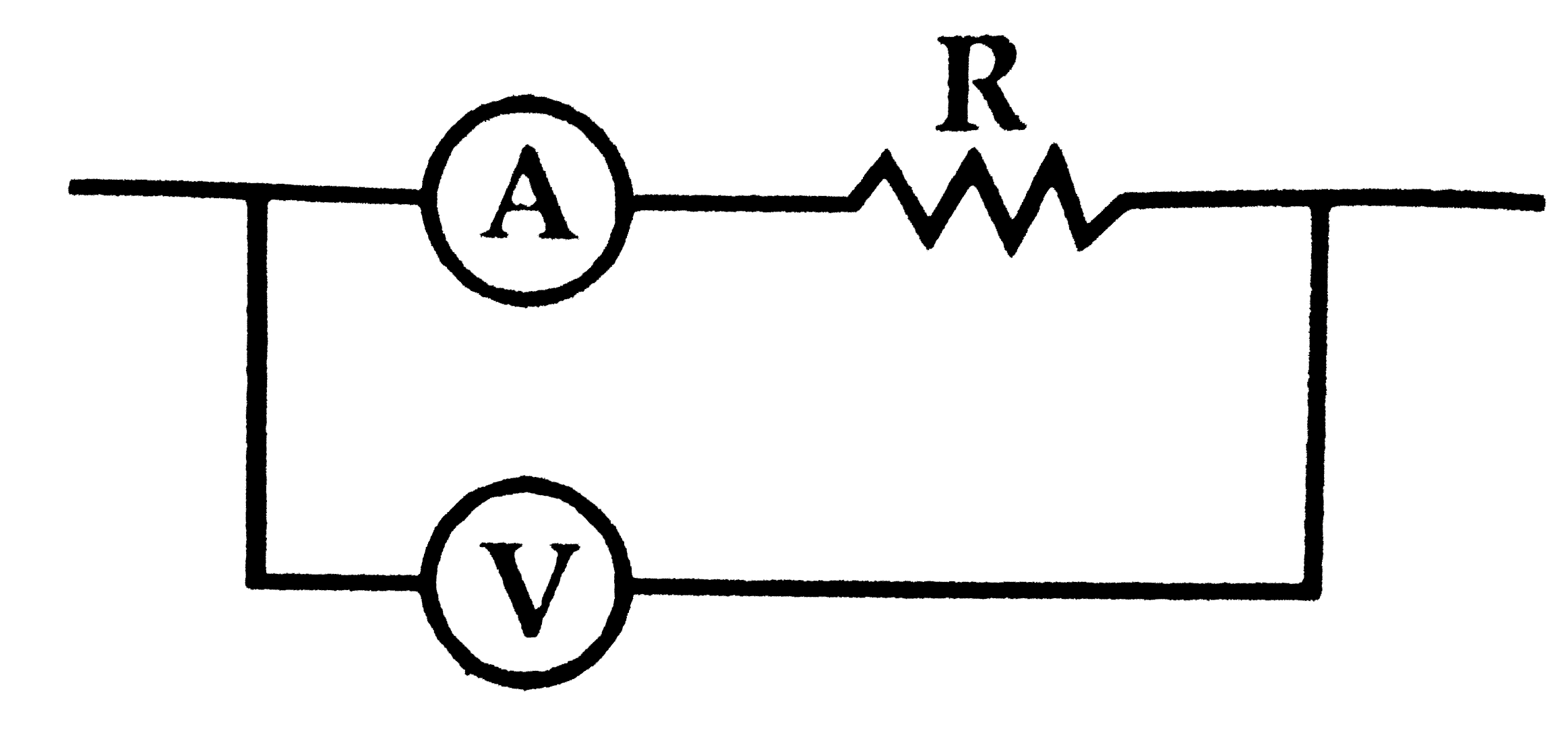
In given figure the ammeter A reads 5 A and voltmeter V reads 40 V. The actual value of resistance R is
 View Solution
In given figure an ammeter reads 5 A and voltmeter reads 40 V. The actual value of resistance R is
 View Solution
In the circuit shown, A and V are ideal ammeter and voltmeter respectively. Reading of the voltmeter will be
 View Solution
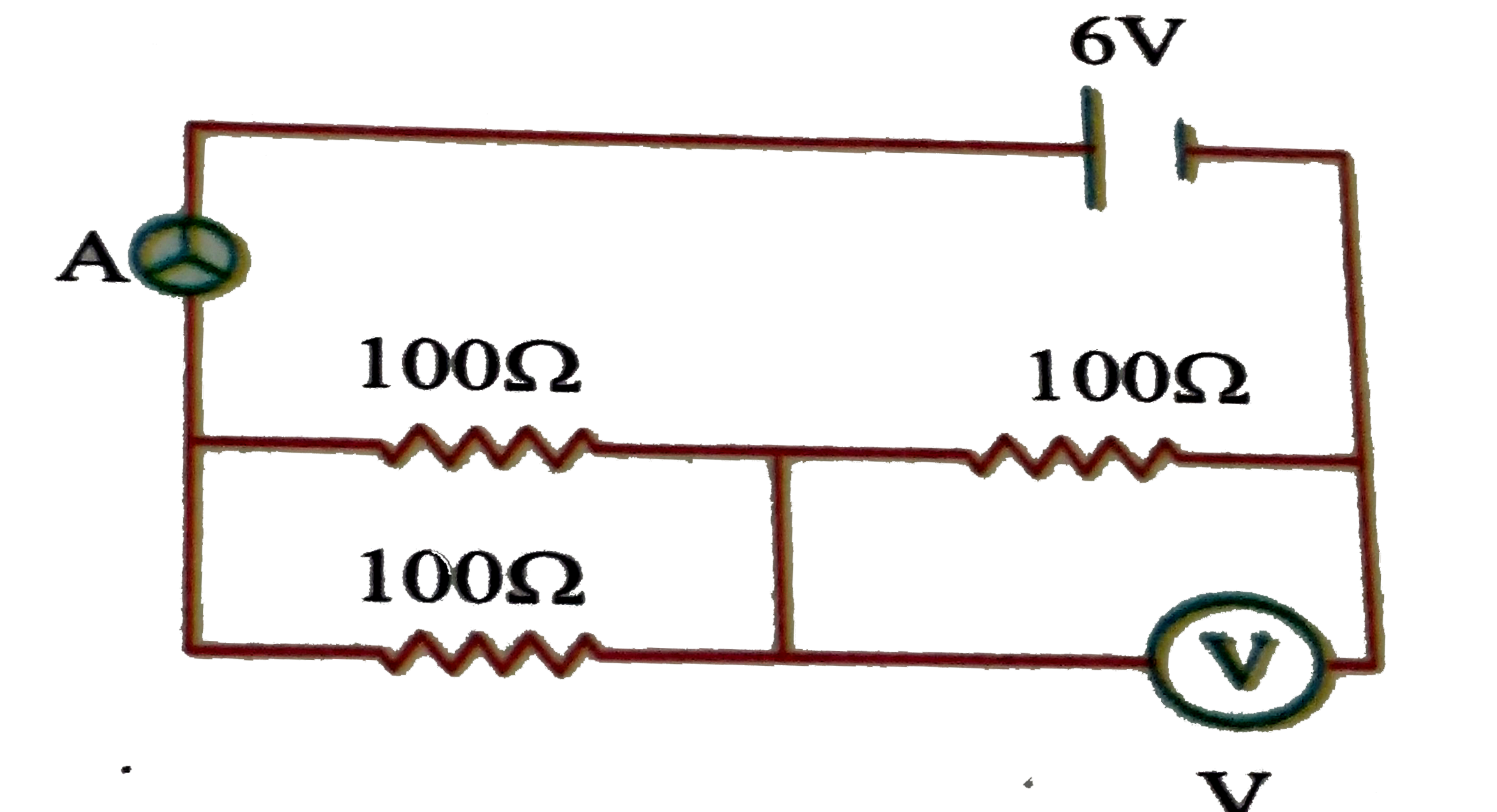
In the circuit shown, the reading of the voltmeter and the ammeter areView SolutionIn the circuit shown below, the ammeter A reads 5 A and the voltmeter V reads 20 V The correct value of resistance R is
 View Solution
