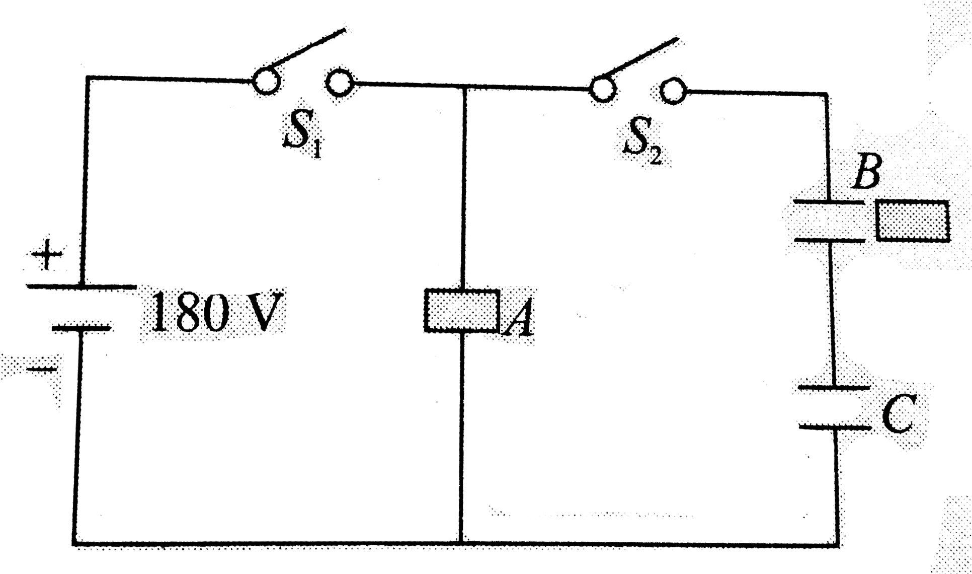
In the circuit shown in , capacitor A has capacitance C1=2μF when filled with a dielectric slab (k=2). Capacitors B and C are air capacitors and have capacitances C2=3μF and C3=6μF, respectively.
 .
.
A is charged by closing the switch S1 alone.
i. Calculate the energy supplied by the battery during the process of charging.
Switch S1is now opened and is closed.
ii. Calculate the charge on B and the energy stored in the system when an electrical equilibrium is atained.
Now switch S2 is also opened, and the slab of A is removed. Another dielectric slab of K=2, which can just fill the space in B, is inserted into it and then switch S2 alone is closed.
iii. Calculate by how many time the electric field in B is increased. Calculate also the loss of energy during the redistribution of charge.
When switch S1 alone is closed, capacitor A gets directly connected across the battery. Thus, charge on A in steady state is
q0=C1V=2×180=360μC
This whole charge is supplied by the battery at emf V=180V. Therefore, the energy supplied by the battery during the charging of capacitor A is
Wbattery=q0V=0.0648J
But the energy stored in capacitor A is
U1=12q0v=0.0324J
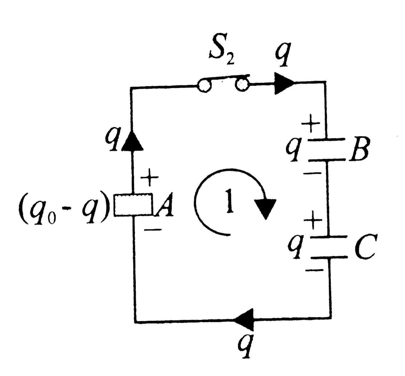
The remaining part of the energy supplied by the battery is converted into heat during the flow of current through the connecting wires. After A is charged switch S1 is opened, which disconnects the battery. When S2 is closed, some charge is transferred form capacitor A to
capacitors B and C. Let the charge transferred be q. In steady state, charges
on the capacitors will be as shown in fig Applying Kirchhoff's loop law,
(1) qC2+qC3−(q0−q)C=0 or q=180μC
Now energy stored in the system of capacitors is
U2=UA+IB+UC=(q0−q)22C1+q22C2+q22C3=0.0162J
Electric field B is E=q/ε0A, where A is the area of plates of capacitor B. Now after the opening of switch S2 the dielectric slab of A is removed, therefore, its capacitance becomes
 .
.
C'1=1μF
Another plate of K=2 is inserted in capacitor B. Therefore, its capacitance becomes C'2=KC2
=6μF.
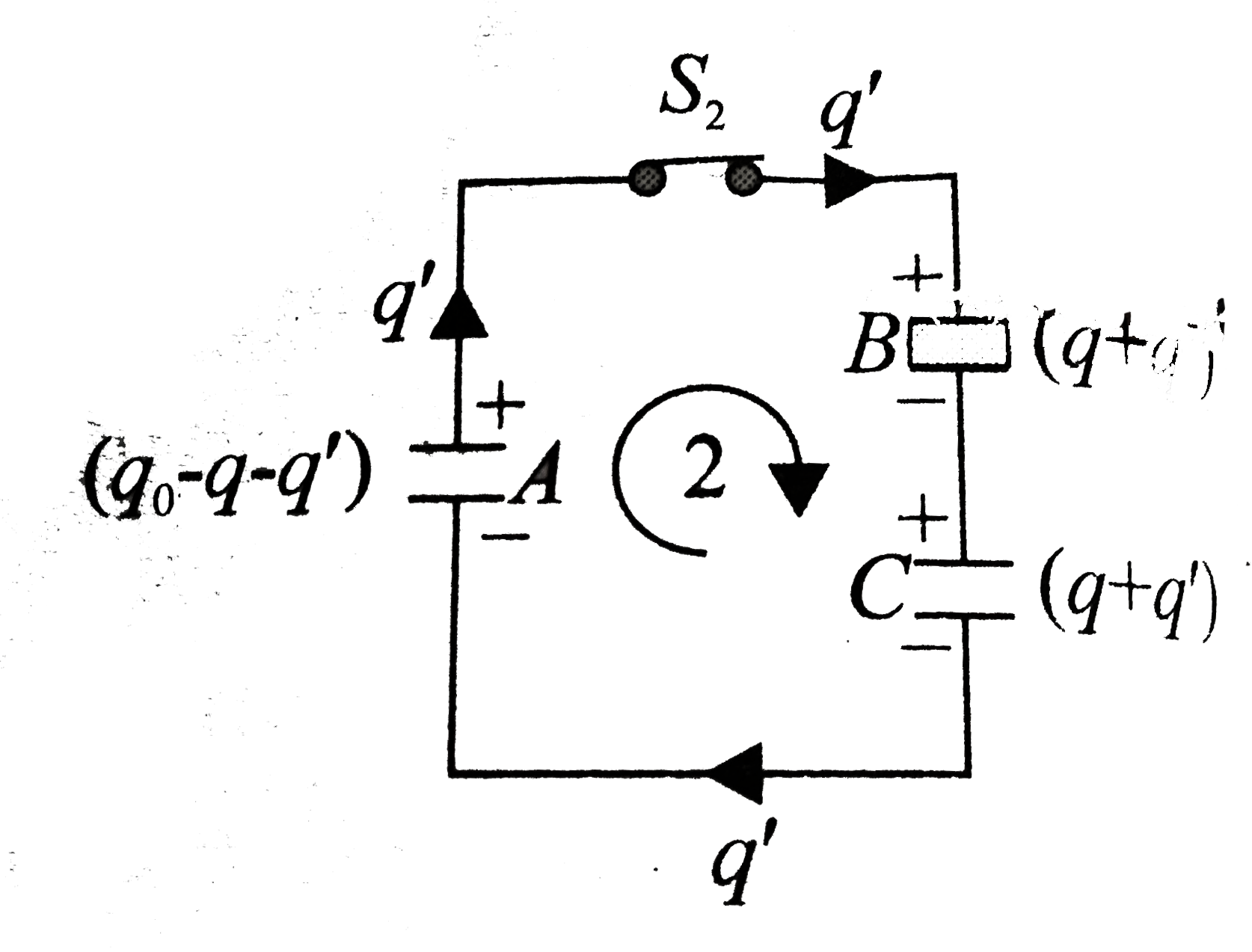
Now switch S2 is closed and charge gets redistributed. charge q' be further transferred from A to capacitors B to C. In steady state, charges will be as shown in . Applying Kirchhoff's loop law,
(2) q+q'C'2+q+q'C3=(q0−q−q')C'1=0q'=90μC
Final charge on capacitor B is q+q'=27μC. Hence, electric field inside it is
E'=q+q'εKA
Factor, by which the electric field in capacitor B is increased is
E'E=(qq')qK=0.75
During the redistribution of charge, energy is lost in the form of heat froduced in the connecting and is equal to Hence, energy lost is
(−q')22C'1=(q')22C'2+(q')22C3=5.4×10⁻³J.
Topper's Solved these Questions
- CAPACITOR AND CAPACITANCEBOOK - CENGAGE PHYSICSCHAPTER - CAPACITOR AND CAPACITANCEEXERCISE - Exercise 4.1
13 Videos
- CAPACITOR AND CAPACITANCEBOOK - CENGAGE PHYSICSCHAPTER - CAPACITOR AND CAPACITANCEEXERCISE - Exercise 4.2
32 Videos
- CAPACITOR AND CAPACITANCEBOOK - CENGAGE PHYSICSCHAPTER - CAPACITOR AND CAPACITANCEEXERCISE - Integer
5 Videos
- ATOMSBOOK - CENGAGE PHYSICSCHAPTER - ATOMSEXERCISE - QUESTION BANK
40 Videos
- CENGAGE PHYSICS DPPBOOK - CENGAGE PHYSICSCHAPTER - CENGAGE PHYSICS DPPEXERCISE - subjective type
51 Videos
Similar Questions
In the circuit shown in figure, capacitor A has capacitance C1=2μF when filled with a di-electric slab of dielectric constant k=2. Capacitors B and C are air capacitors and have capacitances C2=3μF and C3=6μF, respectively. A is charged by closing switch S1 alone
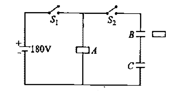
(a) Calculate energy supplied by battery during process of charging. Switch S1 is now opened and S2 is closed.
(b) Calculate charge on B and energy stored in the system when electrical equilibrium is attained. Now switch S2 is also opened, slab of A is removed. Another di-electric slab of K=2, which can just fill the space in B, is inserted into it and then switch S2 alone is closed.
(c) Calculate by how many times electric field in B is increased. Calculate also, loss. of energy during redistribution of charge.
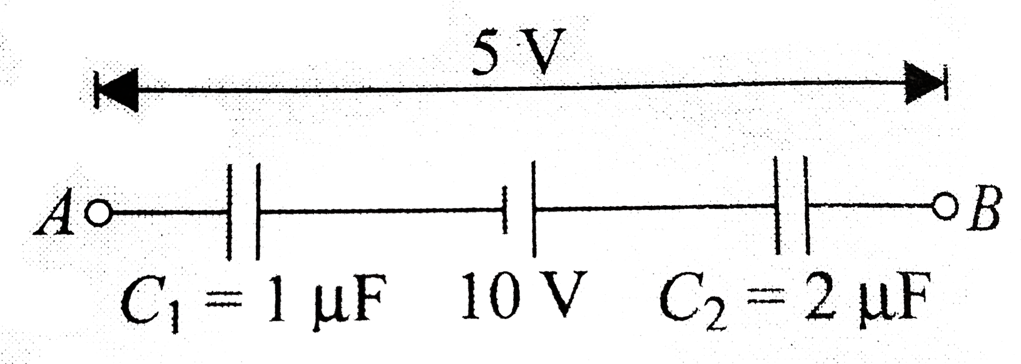
View SolutionA circuit has section AB as shown in The emf of the cell is 10V, and the capacitors have capacitances C1=1μF and C2=2μF.
 .
.
View SolutionIn the circuit shown the capacitors are C1=15μF,C2=10μFandC3=25μF. Find
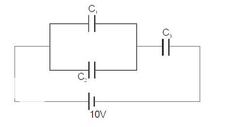
the charge on each capacitor and
View SolutionIn the circuit shown the capacitors are C1=15μF,C2=10μFandC3=25μF. Find
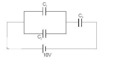
the equivalent capacitance of the circuit.
View SolutionA circuit has section AB as shown in The emf of the cell is 10V, and the capacitors have capacitances C1=1μF and C2=2μF. Find the voltage across each capacitor.
 .
.
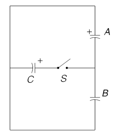
View SolutionIn the given circuit it is known that the capacitor A has a capacitance of 2μF and carries a charge of 40μC. Capacitor C has a capacitance of 6μF and carries a charge of 180μC. The positive plate of both capacitors has been indicated in the Figure. Capacitance of capacitor B is 3μF. Calculate charge on B after the switch S is closed.
View SolutionTwo capacitors of capacitances C1=2μF and C2=8μF are connected in series and the resulting combination is connected across a 300V battery. Calculate the charge, potential difference and energy stored in the capacitor separately.
View SolutionTwo capacitors of capacitances C1=2μF and C2=8μF are connected in series and the resulting combination is connected across a 300V battery. Calculate the charge, potential difference and energy stored in the capacitor separately.
View SolutionThree capacitors C1=3μF,C2=6μFandC3=10μF are connected to a 50 V battery as shown in the figure below:
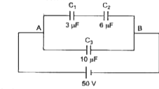
Calculate :
The charge on C1
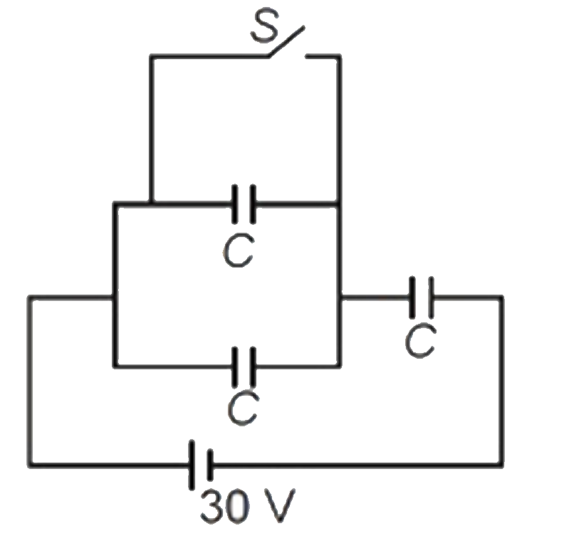
View SolutionThree capacitors each of capacitance C=2μF are connected with a battery of emf 30 V as shown in the figure . When the switch S is closed , the heat generated in the circuit will be
View Solution
