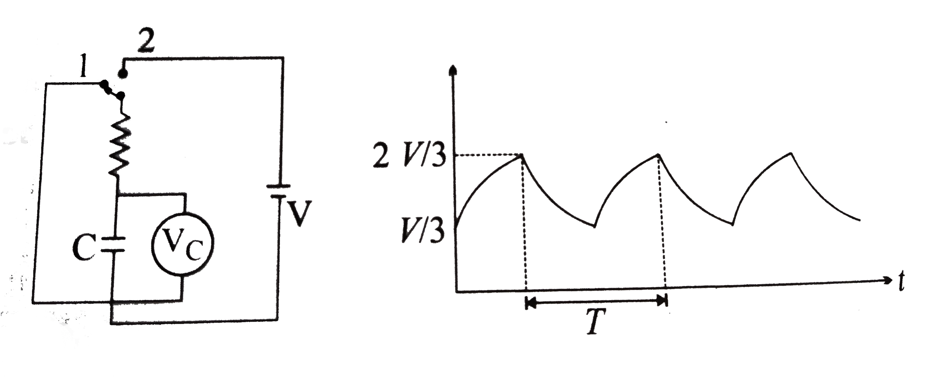
VC is the ideal voltmeter in the figure. Resistance of the resistor shown is R. Initially the switch is in position 2 when charging of the capacitor starts. Initially the capacitor was uncharged. The switch in circuit shifts automatically from 2 to 1 when VC>2V/3 and goes back to 2 from 1 when VC<V/3. The ideal voltmeter reads voltage across capacitor as plotted. What is the period T of the wave from in terms of R and C ?
 ,
,
3RC1n3
2RC1n2
(RC/2)1n2
none of these
The correct Answer is:B
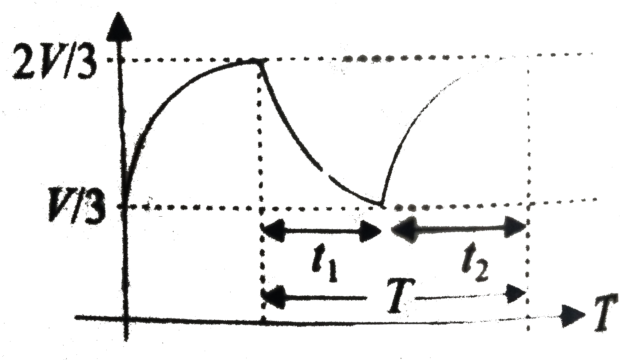
b. t1 is the time of capacitor to discharge from 2V/3 to V/3.
For this , V3=2V2e−t1/τ or t1=τ1n2=RC1n2
t2 is time for charging of capacitor
from V/3to2V/3.
So ∫2VC/3VC/3dqVC−q=∫t20dtRC
or t2=RC1n2
T=t1+t2=2RC1n2
 .
.
Similar Questions
The switch in Figure (a) closes when Vc=2V/3 and opens when Vc=V/3. The voltmeter reads a voltage as plotted in figure (b). What is the period T of the waveform? (take R1=6R and R2=3R, and ln2=0.7 if required)
(a)
View SolutionCondsider
 .
.
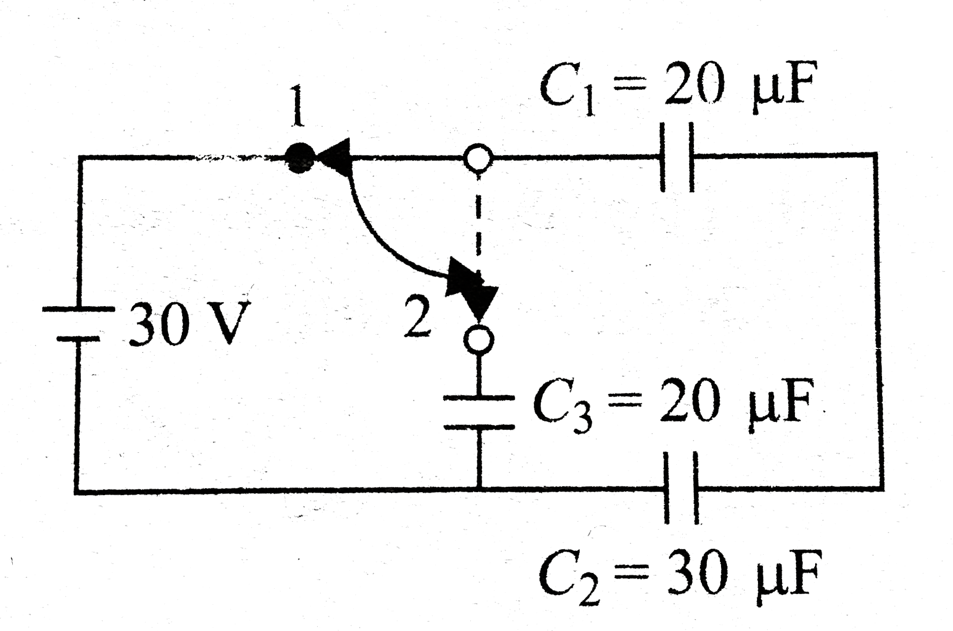
In the circuit shown is the switch can be shifted to positions 1 and 2 The charge on capacitor C1 when the switch is at position 1 is.
View Solution
Knowledge Check
The switch in Figure (a) closes when Vc=2V/3 and opens when Vc=V/3. The voltmeter reads a voltage as plotted in figure (b). What is the period T of the waveform? (take R1=6R and R2=3R, and ln2=0.7 if required)
(a) A12RCB8.4RCC11RCDnone of these
Condsider
 .
.
In the circuit shown is the switch can be shifted to positions 1 and 2 The charge on capacitor C1 when the switch is at position 1 is.A120μCB240μCC360μCD80μCIn the circuit shown in fig. C1=2C2 Initially, capacitor C1 is charged to a potential of V. The current in the circuit just after the switch S is closed is
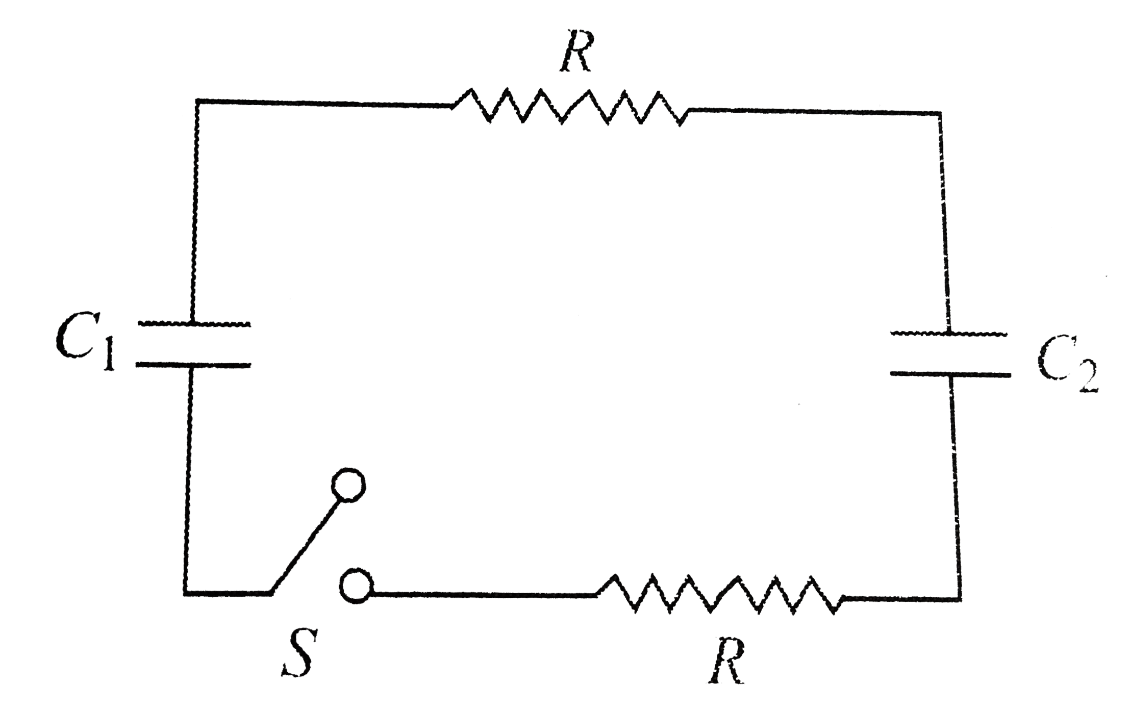 A0B2V/RC∞DV/2R
Passage-III
In the circuit shown, the battery is ideal with emf V. The capacitor is initially uncharged. The switch is closed at time t = 0
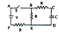
The current in the branch BE at t=∞ is
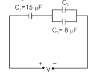
View SolutionIn the circuit shown in the figure, the total charge is 750μC and the voltage across capacitor C2 is 20 V. Then the charge on capacitor C2 is:
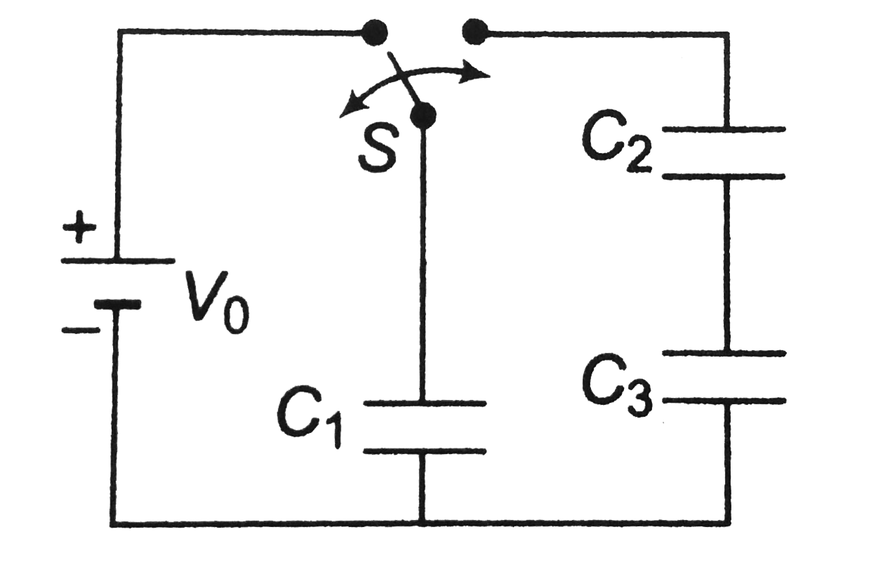
View SolutionWhen switch S is thrown to the left in figure, the plates of capacitor 1 acquire a potential difference V0. Capacitors 2 and 3 are initially uncharged. The switch is now thrown to the right. What are the final charges q1,q2 and q3 on the capacitors?
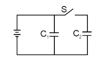
View SolutionTwo capacitors of equal capacitance (C1=C2) are shown in the figure. Initially, while the switch S is open, one of the capacitors is uncharged and the other carries charge Q0. The energy stored in the charged capacitor is U0. Sometimes after the switch is colsed, the capacitors C1andC2 carry charges Q1andQ2, respectively, the voltages across the capacitors are V1andV2, and the energies stored in the capacitors are U1andU2. Which of the following statements is INCORRECT ?
View SolutionIn the circuit shown in the figure, the total charge is 750μC and the voltage across capacitor C2 is 20 V. Then the charge on capacitor C2 is:

View Solution
