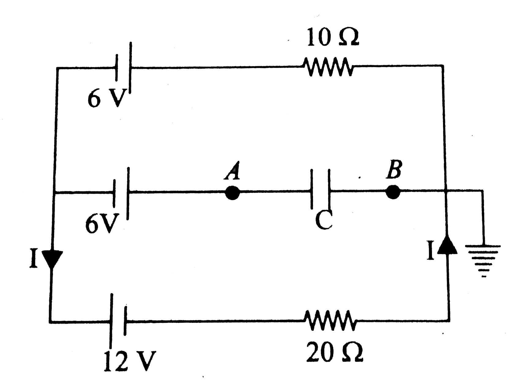
The figure shown is part of the circuit at steady state
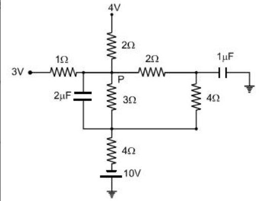
The potential of point P is :
A
1V
B
2V
C
3V
D
4V
Video Solution
Text Solution
NA
|
Topper's Solved these Questions
Similar Questions
Knowledge Check
The figure shown is part of the circuit at steady state

The charge on 2μF capacitor is :A2μCB4μCC6μCD8μCConsider the circuit shwon in fig. The circuit is in steady state.
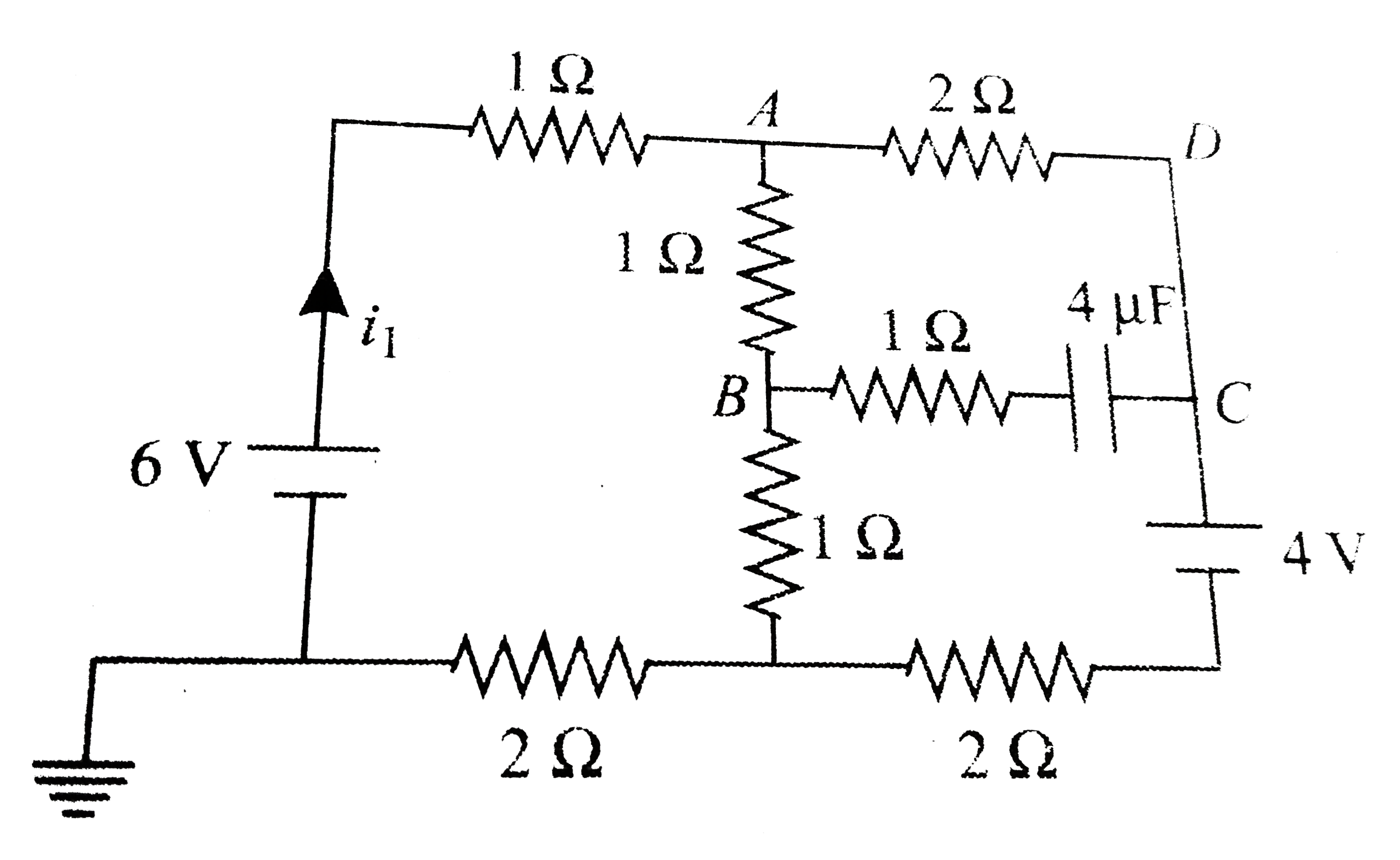
The potential of point B isA27/34VB46/13VC1/2VD61/49VThe figure shows a part of the circuit in the steady state. The currents, the valuces of resistances and emfs of the cells are shown in the figure. The circuit also contains a capacitor of capacitance C=μF. The value of i1 is-
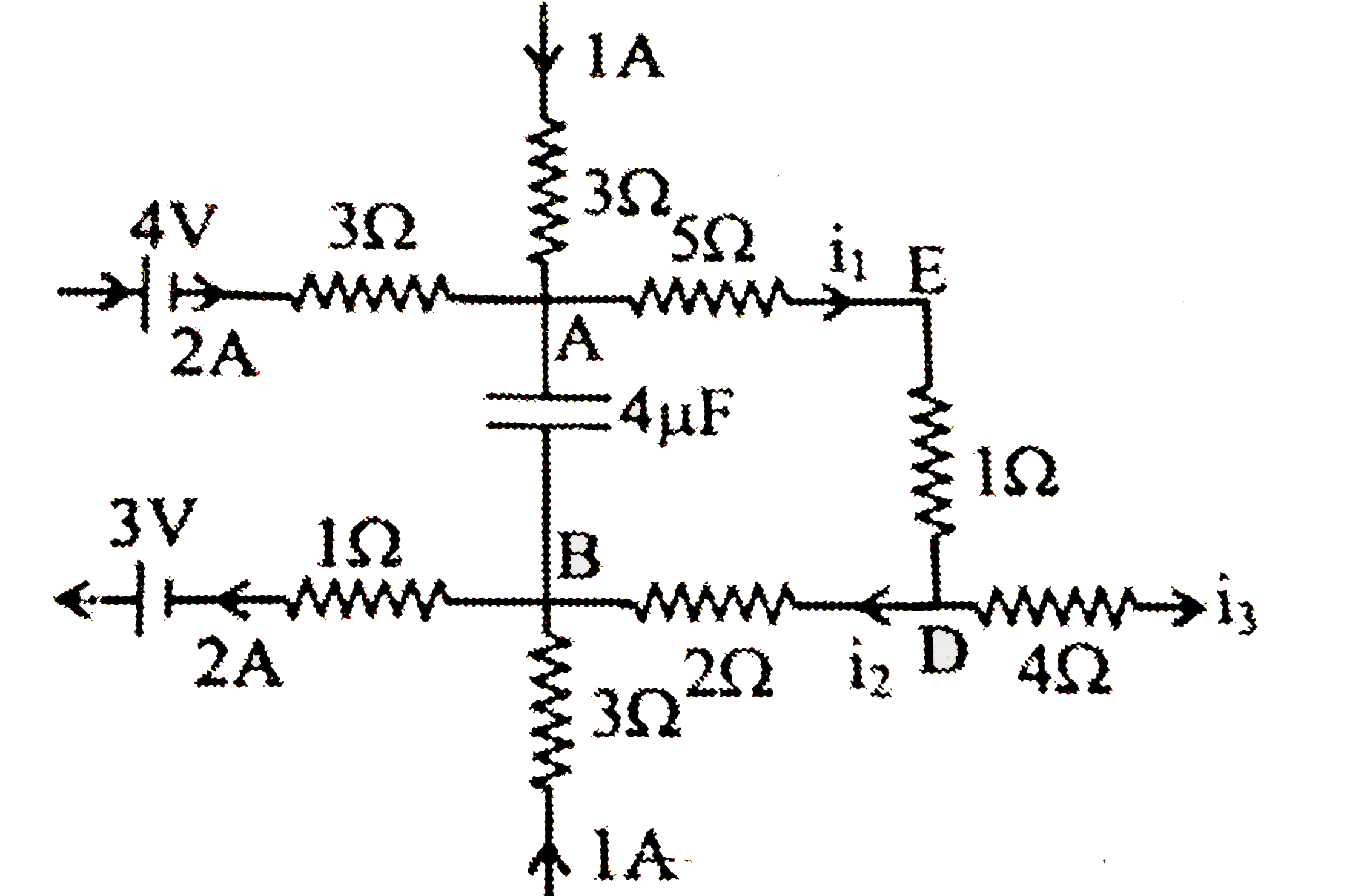 A1AB2AC3AD4A
Figure shows part of a circuit. Which points have the same potential as that of point a

View SolutionIn the fig. shown the circuit is in steady state.
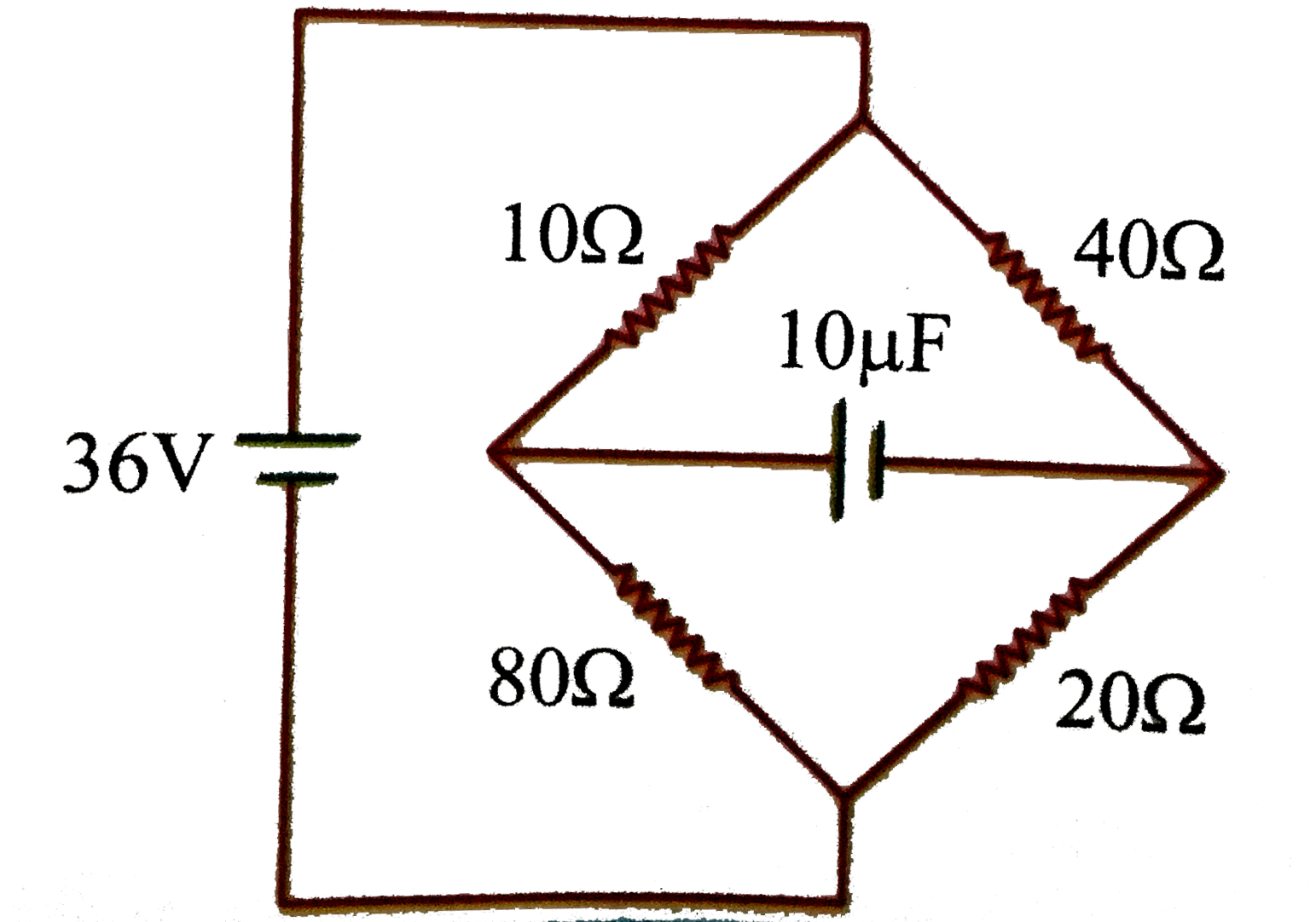
what is the potential difference across the capacitor in steady state ?
View SolutionIn the circuit shown in the figure, if the potential at point A behind to be zero, the potential at point B is :
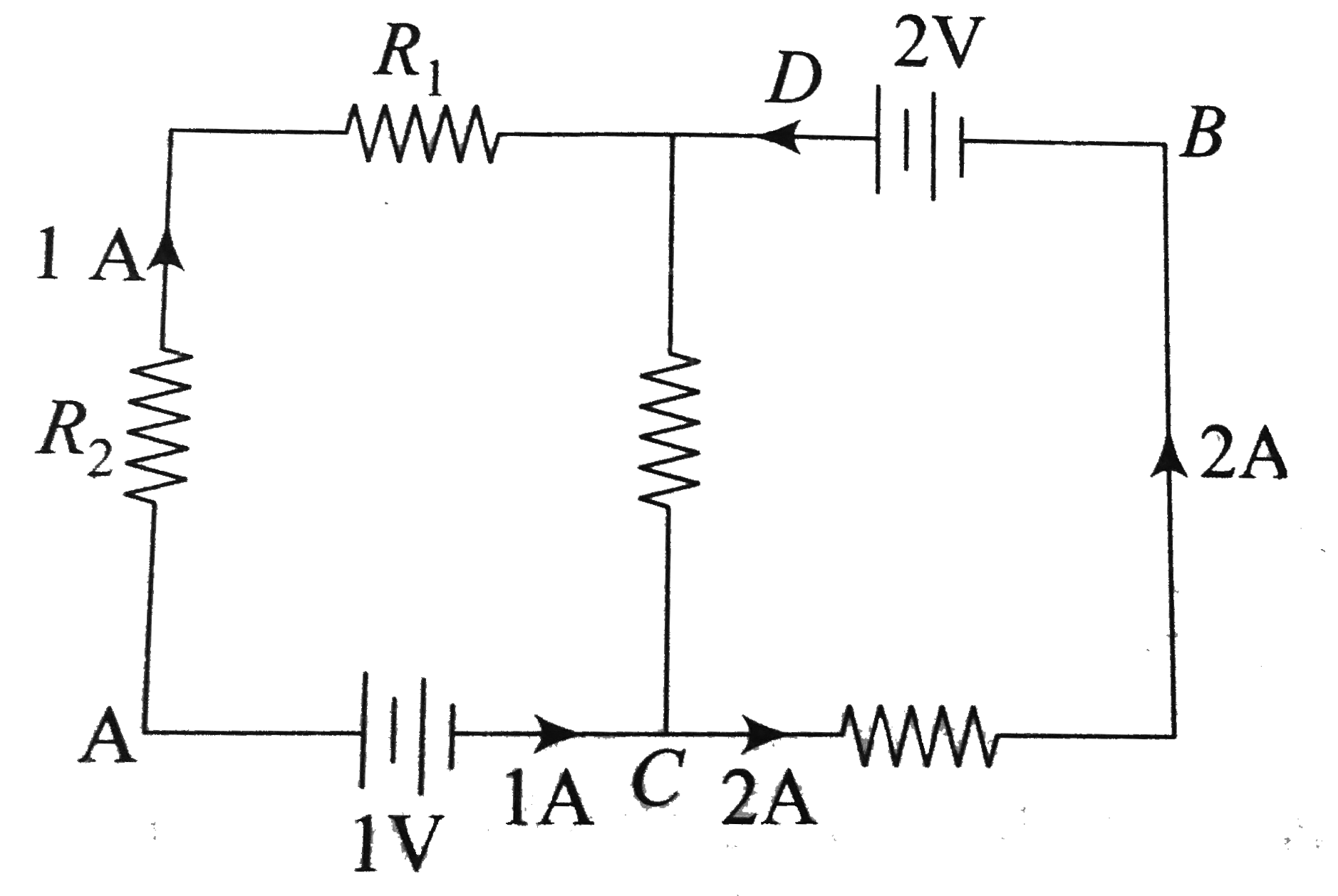
View SolutionIn the circuit shown in the figure, if potentail at point A is taken to be zero, the potential at point B is
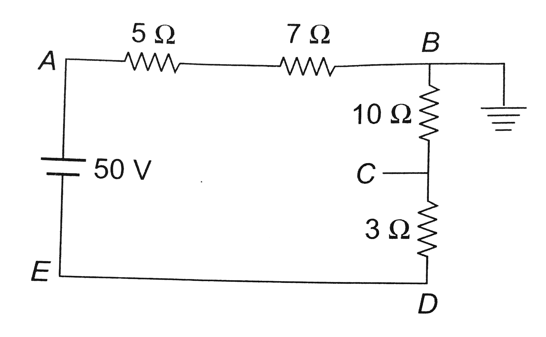
View SolutionIn the circuit shown, the point B is earthed. The potential at the point 'A' is
View Solution


