The effective resistance between points P and Q of the
electrical circuit shown in the figure is
(a) 2RrR+r
(b)8R(R+r)3R+r
(c) 2r+4R
(d) 5R2+2r .
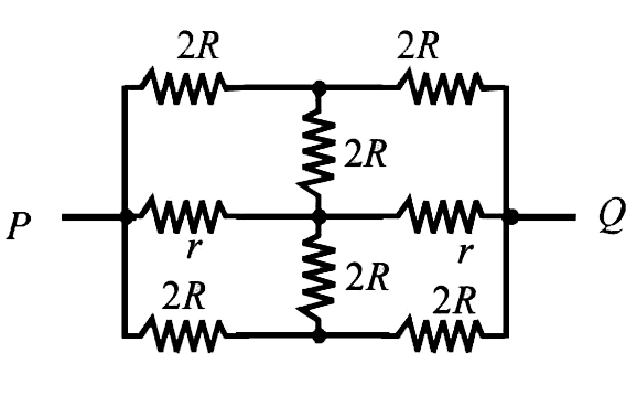 .
.
2Rr/(R+r)
8R(R+r)/(3R+r)
2r+4R
5R/2+2r
The correct Answer is:A
(a) 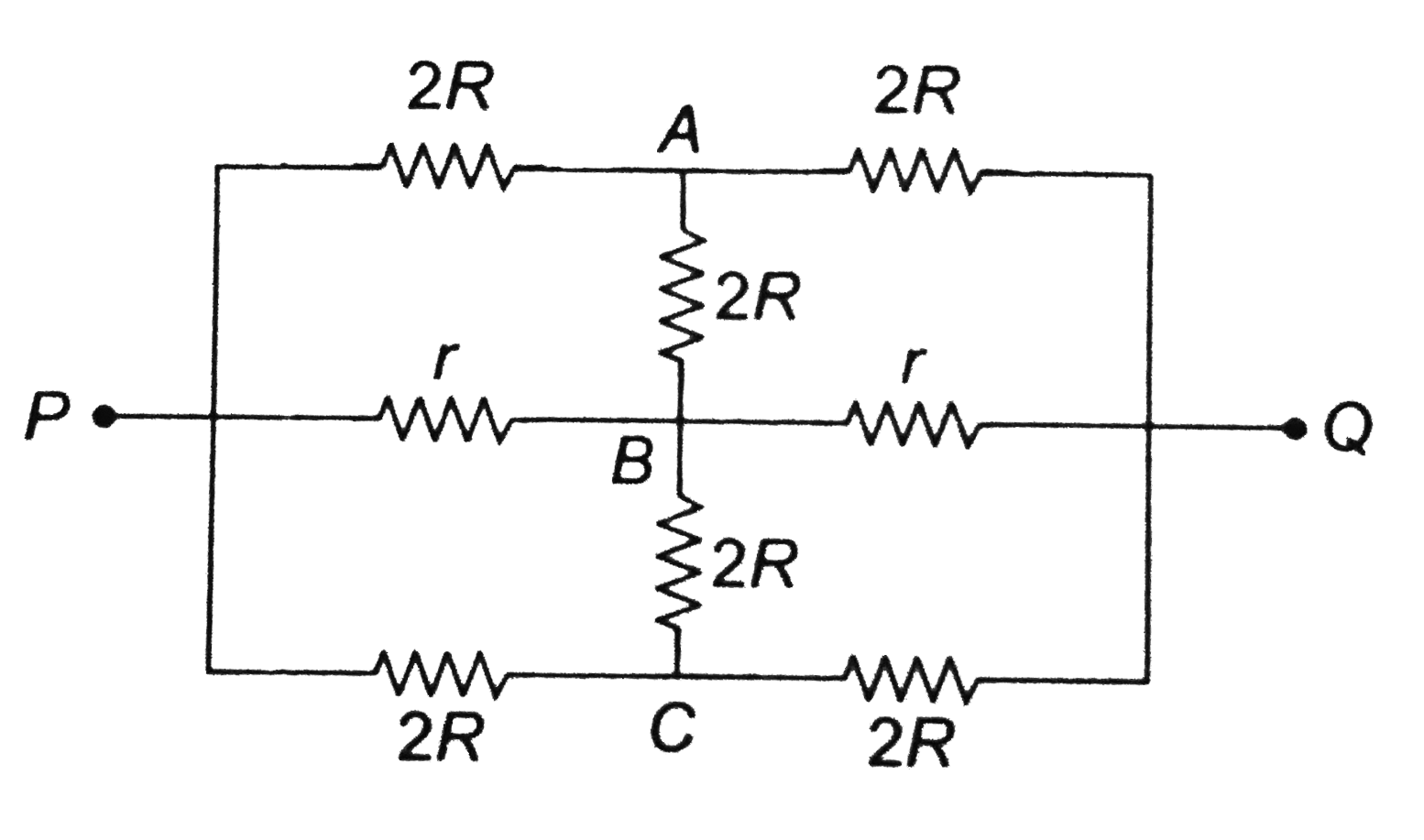
In a circuit, any circuit element placed between points at the same potential can be removed, without affecting the rest of the circuit. Here, by symmetry, point A,B and C are at same potential, for any potential difference between P and Q
The circuit can therefore be reduced as shown below
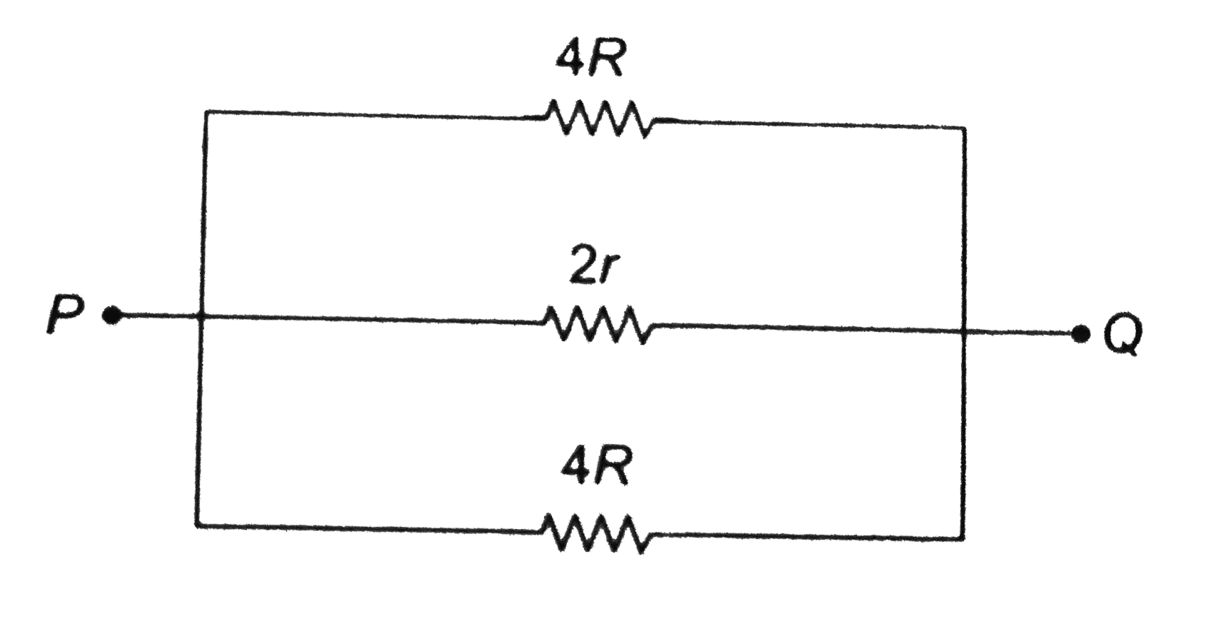
Effective resistance Req=2RrR+r.
Topper's Solved these Questions
- CURRENT ELECTRICITYBOOK - A2ZCHAPTER - CURRENT ELECTRICITYEXERCISE - Kircoff'S Laws And Simple Circuits
64 Videos
- CURRENT ELECTRICITYBOOK - A2ZCHAPTER - CURRENT ELECTRICITYEXERCISE - R-C Circuits
17 Videos
- CURRENT ELECTRICITYBOOK - A2ZCHAPTER - CURRENT ELECTRICITYEXERCISE - Section D - Chapter End Test
29 Videos
- ATOMIC PHYSICSBOOK - A2ZCHAPTER - ATOMIC PHYSICSEXERCISE - Section D - Chapter End Test
30 Videos
- DUAL NATURE OF RADIATION AND MATTERBOOK - A2ZCHAPTER - DUAL NATURE OF RADIATION AND MATTEREXERCISE - Section D - Chapter End Test
30 Videos
Similar Questions
Knowledge Check
The effective resistance between points P and Q of the
electrical circuit shown in the figure is
(a) 2RrR+r
(b)8R(R+r)3R+r
© 2r+4R
(d) 5R2+2r .
 .A2RrR+rB8R(R+r)3R+rC2r+4RD5R2+2r
In the circuit shown in the given figure, the resistances R1andR2 are respectively
 A14Ωand40ΩB40Ωand44ΩC40Ωand30ΩD14Ωand30Ω
In the circuit shown in figure
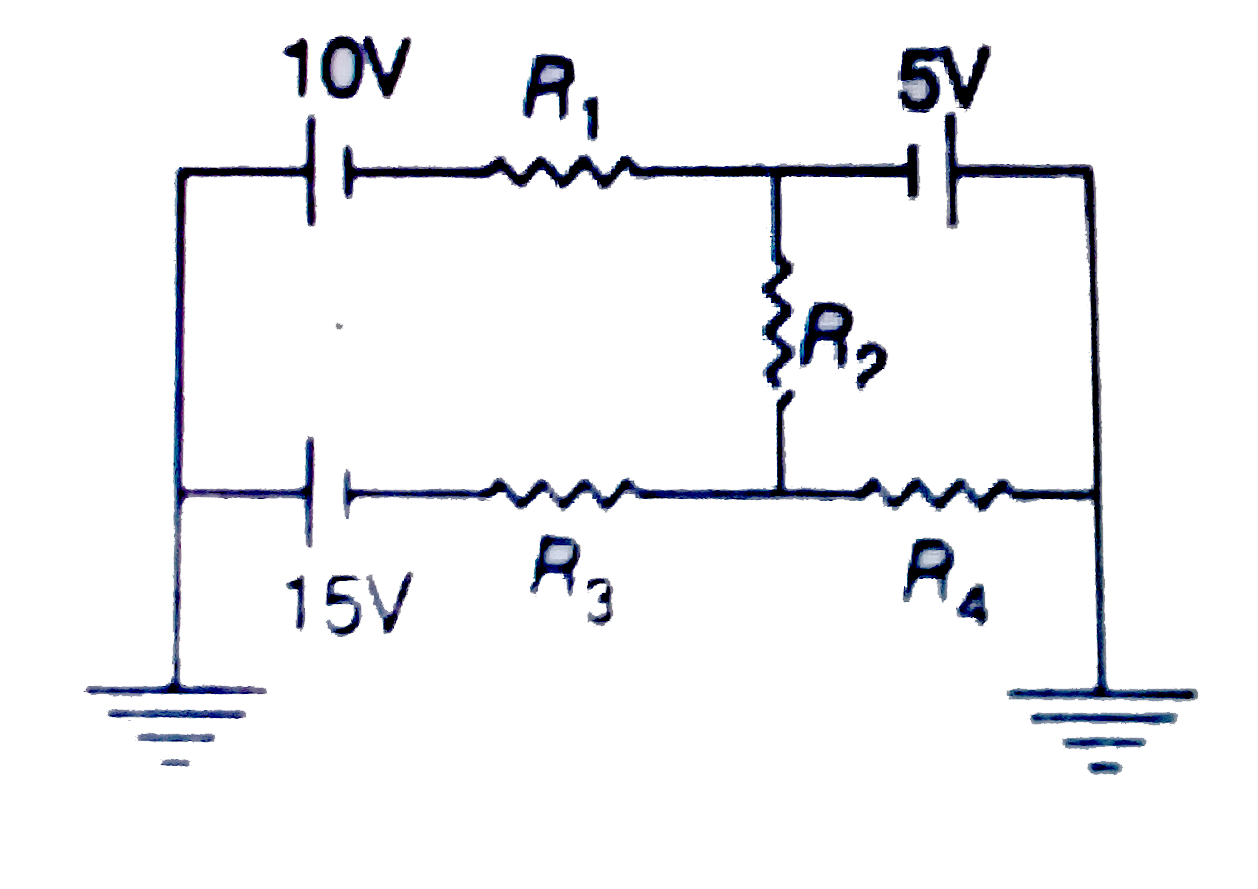
For what ratio R2R4, current through R3 will be zeroA1:1B1:2C1:3DNot possible
[" The effective resistance "],[" between points "A" and "B" is "],[[" A "R],[qquad (d)/(R)" ? "]]
View Solution[" The effective resistance "],[" between points "A" and "B" is "],[[" A "R],[qquad (d)/(R)" ? "]]
View SolutionIn the circuit shown in figure , R1=R2=R3=R. Match the following
View SolutionA wire of resistance R is bent in the form of a circle effective resistance across diameter is (A) R (R)/(4) (B) (R)/(8) (D) (R)/(16)
View SolutionThree resistors R1,R2 and R3 are to be combined to form an electrical circuit as shown in the figure. It is found that when R1R2andR3 are put respectively in positions A, B and C, the effective resistance of the circuit is 70 ΩWhen R2,R3andR1 are put respectively in position A, B and C the effective resistance is 35Ω and when R3,R1andR2 are respectively put in the position A, B and C, the effective resistance is 42Ω
IfR_(1), R_(2)and R,_(3)are put in series, the effective resistance will be
View Solution