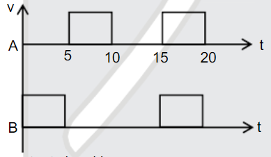
The inputs to the digital circuit are shown below. The output Y is

A
A+B+¯¯¯C
B
(A+B)¯¯¯C
C
¯¯¯A+¯¯¯B+¯¯¯C
D
¯¯¯A+¯¯¯B+C
Text Solution
If the inputs of the rightmost OR gate are M and N,
Y = M + N = ¯¯¯¯¯¯AB+¯¯¯C=¯¯¯A+¯¯¯B+¯¯¯C
The option ( C) is correct.
|
Topper's Solved these Questions
- DIGITAL CIRCUITS BOOK - CHHAYA PUBLICATIONCHAPTER - DIGITAL CIRCUITS EXERCISE - EXAMINATION ARCHIVE WITH SOLUTIONS ( JEE Main)
1 Videos
- DIGITAL CIRCUITS BOOK - CHHAYA PUBLICATIONCHAPTER - DIGITAL CIRCUITS EXERCISE - EXAMINATION ARCHIVE WITH SOLUTIONS (AIPMT)
1 Videos
- DIGITAL CIRCUITS BOOK - CHHAYA PUBLICATIONCHAPTER - DIGITAL CIRCUITS EXERCISE - EXAMINATION ARCHIVE WITH SOLUTIONS (WBCHSE)
10 Videos
- DIFFRACTION AND POLARISATION OF LIGHTBOOK - CHHAYA PUBLICATIONCHAPTER - DIFFRACTION AND POLARISATION OF LIGHTEXERCISE - CBSE SCANNER
27 Videos
- ELECTRIC ENERGY AND POWERBOOK - CHHAYA PUBLICATIONCHAPTER - ELECTRIC ENERGY AND POWEREXERCISE - CBSE SCANNER
7 Videos
Similar Questions
Knowledge Check
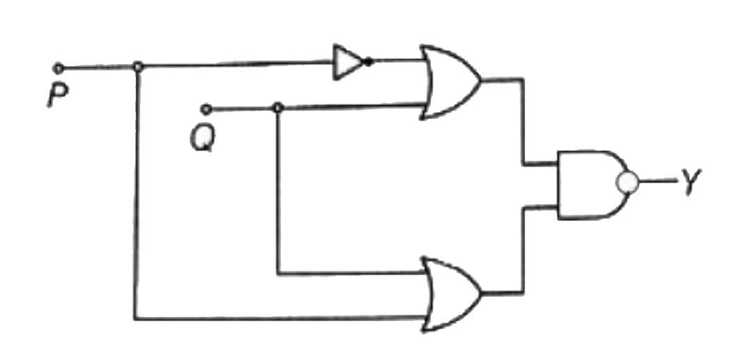
In the given circuit P and Q from the inputs. The output Y is
 AY=¯¯¯PBY=P¯¯¯QCY=P+QDY=¯¯¯Q
The output Y of the logic circuit as shown in figure is
 A(A+B)⋅¯¯¯CB(A+C)⋅¯¯¯CC(B+C)⋅¯¯¯ADA+B+C
To get an output y=1 from the circuit shown below, the input must be
 AABC010BABC001CABC101DABC100
In the given circuit P and Q from the inputs. The output Y is

View Solution
input are given as shown

then output signal is-
View SolutionOutput of the circuit shown below will be

View SolutionThe output Y of the gate circuit shown in the figure below is

View SolutionThe output Y of the gate circuit shown in the figure below is

View Solution

