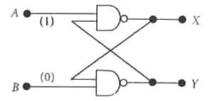
In the circuit shown, inputs A and B are in states 1 and 0 respectively. What is the only possible stable sate of the outputs X and Y?

X = 1, Y = 1
X = 1, Y = 0
X = 0, Y = 1
X = 0, Y = 0
For the option A-
given, A = 1 and B = 0.
If X = 1, then Y wil be 1. At that instant the state of X should be 0.
But It given that X = 1.
∴ The option A is not correct.
Only the option C correctly describe the circuit.
Hence, if X = 0, then Y will be 1. At that instant X = 0.
The option C is correct.
Topper's Solved these Questions
- DIGITAL CIRCUITS BOOK - CHHAYA PUBLICATIONCHAPTER - DIGITAL CIRCUITS EXERCISE - EXAMINATION ARCHIVE WITH SOLUTIONS ( JEE Main)
1 Videos
- DIGITAL CIRCUITS BOOK - CHHAYA PUBLICATIONCHAPTER - DIGITAL CIRCUITS EXERCISE - EXAMINATION ARCHIVE WITH SOLUTIONS (AIPMT)
1 Videos
- DIGITAL CIRCUITS BOOK - CHHAYA PUBLICATIONCHAPTER - DIGITAL CIRCUITS EXERCISE - EXAMINATION ARCHIVE WITH SOLUTIONS (WBCHSE)
10 Videos
- DIFFRACTION AND POLARISATION OF LIGHTBOOK - CHHAYA PUBLICATIONCHAPTER - DIFFRACTION AND POLARISATION OF LIGHTEXERCISE - CBSE SCANNER
27 Videos
- ELECTRIC ENERGY AND POWERBOOK - CHHAYA PUBLICATIONCHAPTER - ELECTRIC ENERGY AND POWEREXERCISE - CBSE SCANNER
7 Videos
Similar Questions
In the circuit shown, inputs A and B are in states '1' and '0' respectively. What is the only possible stable state of the outputs 'X' and 'Y'?

View SolutionIn the given circuit, the binary inputs at A and B are both 1 in one case and both 0 in the next case. The respective outputs at Y in these two cases will be:

View Solution
Knowledge Check
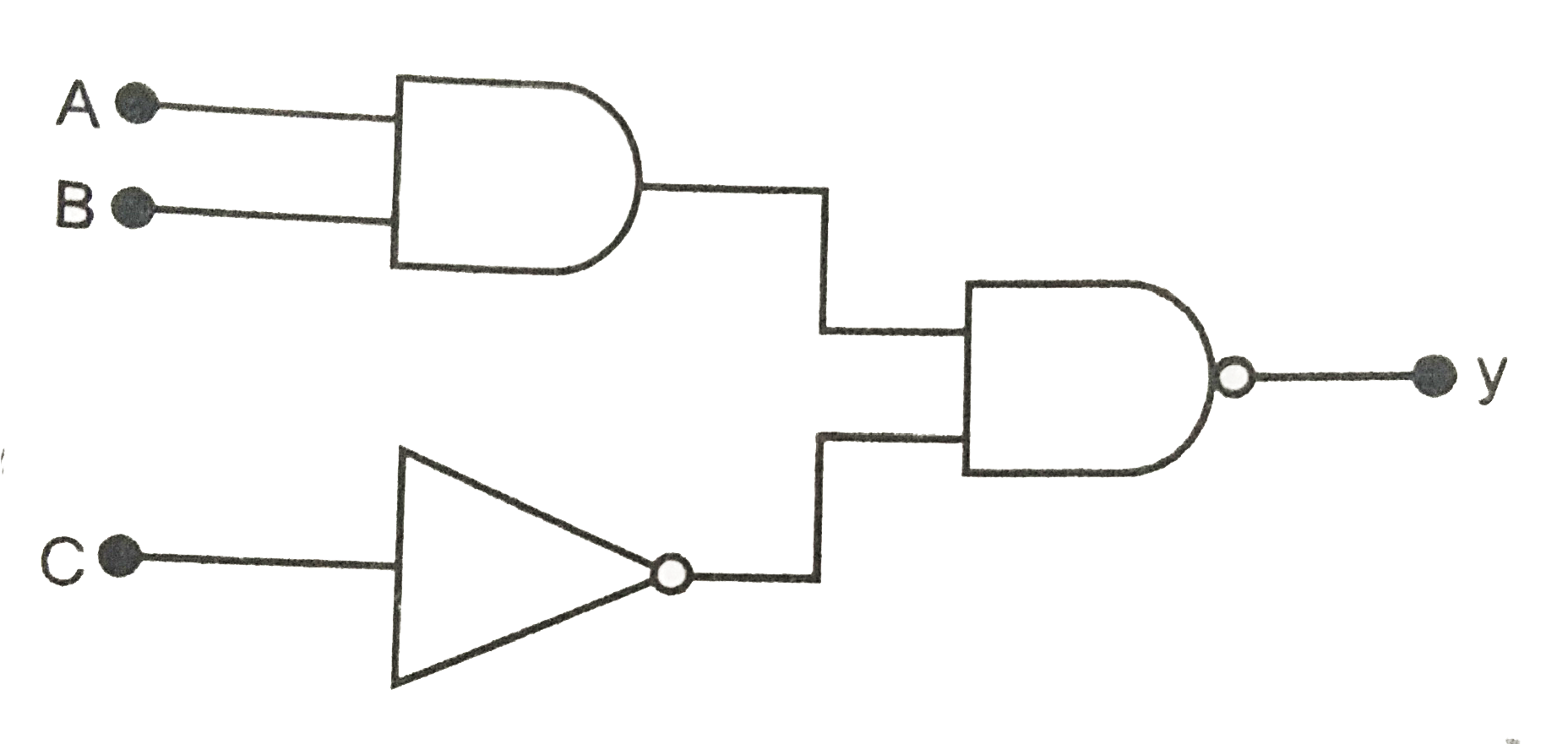
In the circuit givne, A, B and C are inputs and Y is the output.

The output of Y isAhigh for all the high inputsBhigh for all the low inputsChigh when A=1,B=1,C=0Dlow for all low inputsLet inputs of p and q be 1 and 0 respectively in electric circuit . Then output of p∧q is
A1B0CBoth 1 and 0DNeither 1 nor 0In AND gate, the output Y is 1 when the inputs A and B are:
AA=1, B=0BA=1, B=1CA=0, B=0DA=0, B=1
In the logic circuit shown in the figure, if input A and B are 0 to 1 respectively, the output at Y would be ‘x’
The value of x is _______

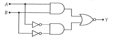
View SolutionIn the following circuit, the output Y for all possible inputs A and B is expressed by the truth table:

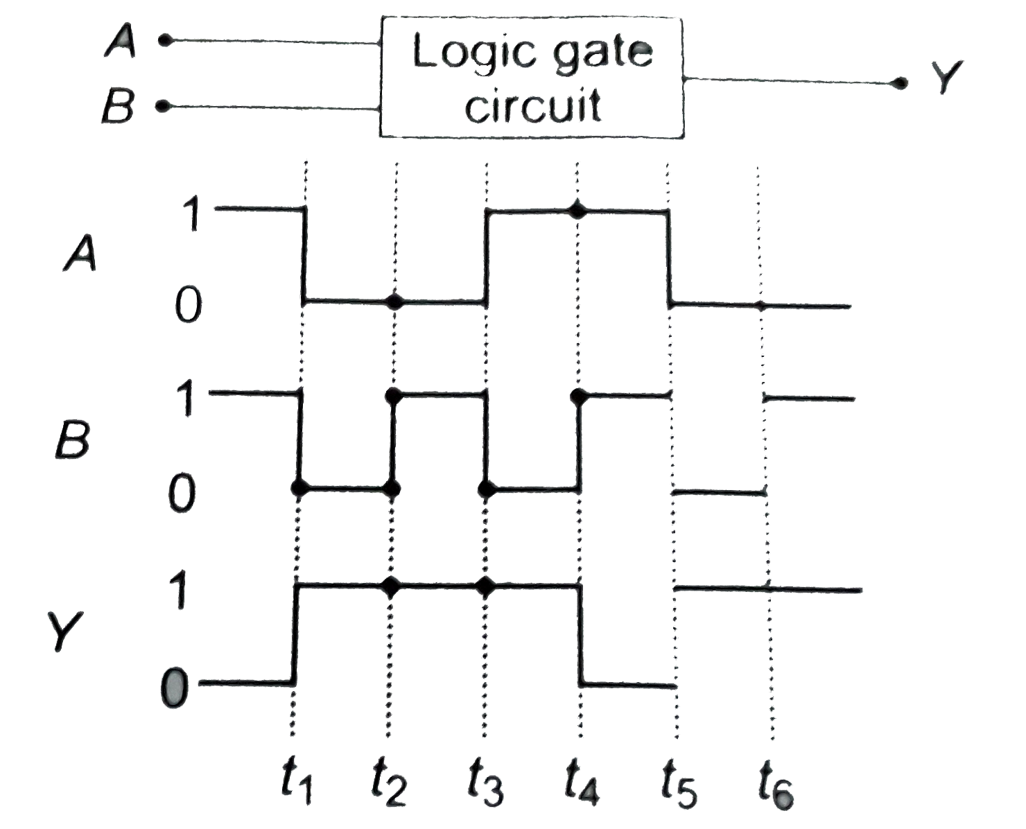
View SolutionThe following figure shows a logic gate circuit with two inputs A and B and the output Y. The voltage waveforms of A,B and the output Y are as given

View SolutionIn the circuit Fig. the output y becomes zero for the inputs

View SolutionIn the following circuit, the output Y for all possible inputs A and B is expressed by the truth table:

View Solution
