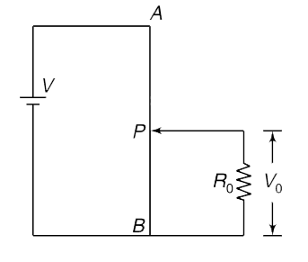
In the circuit shown in figure. AB is a uniform wire of length L and resistance R. P is a sliding contact. Take the ratio of lengths PB to AB as α.
(a) Find the ratio V0V in terms of R0,R and α
(b) Predict the value of V0V when R0rar∞. Use the result obtained in (a) to show that your prediction is correct.
(c) Find the ratio V0V when R0=2Randα=12
The correct Answer is:(a) α(1−α)(αRR0+1)+α
(b) α
(c) 49
Step by step video, text & image solution for In the circuit shown in figure. AB is a uniform wire of length L and resistance R. P is a sliding contact. Take the ratio of lengths PB to AB as alpha. (a) Find the ratio (V_(0))/(V) in terms of R_(0),R and alpha (b) Predict the value of (V_(0))/(V) when R_(0) rar infty. Use the result obtained in (a) to show that your prediction is correct. (c) Find the ratio (V_(0))/(V) when R_(0) = 2R and alpha = (1)/(2) by Physics experts to help you in doubts & scoring excellent marks in Class 12 exams.
Topper's Solved these Questions
Similar Questions
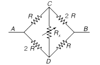
In the circuit shown in the figure RX is a variable resistance. find the equivalent resistance (RAB) between A and B in terms of RandRX. What are the possible range of values of RAB ?
 View Solution
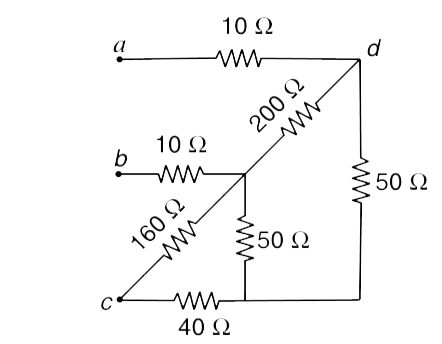
In the circuit shown in the fig the equivalent resistance between aandb is Rab and the equivalent between aandc is Rac. find the ratio Rab:Rac.
 View Solution
Knowledge Check
- Question 1 - Select One
In the circuit shown in figure value of VR is
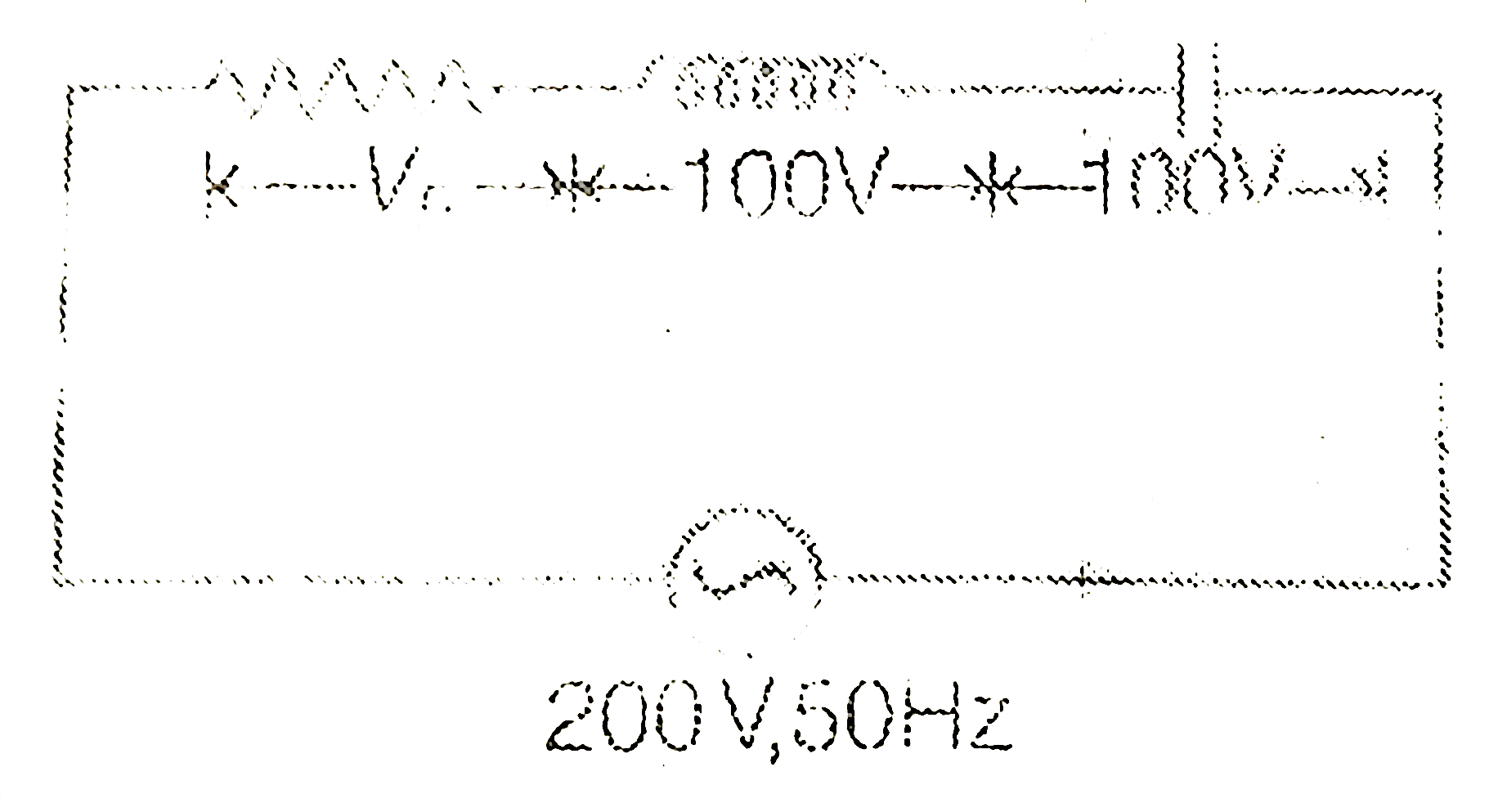 A400VB200VC300VDzero
 - Question 2 - Select One
In the circuit shown in the figure, the ratio of VB as VC is
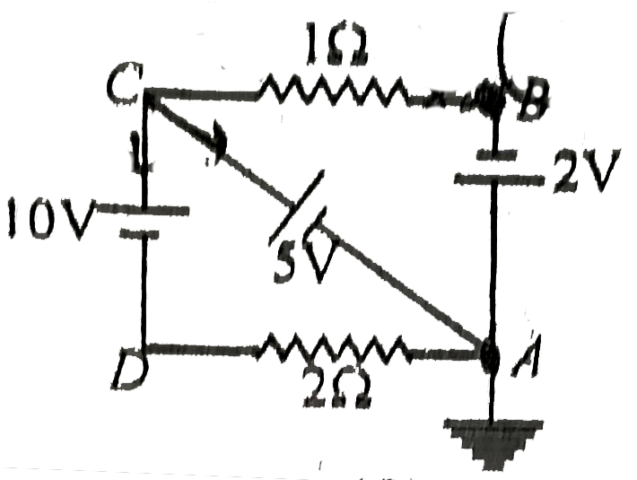 A−2/5B−5/2C1D1/3
 - Question 3 - Select One
In showing figure find VR –
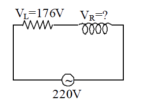 A132 VB396 VC185 VD√220×176 V
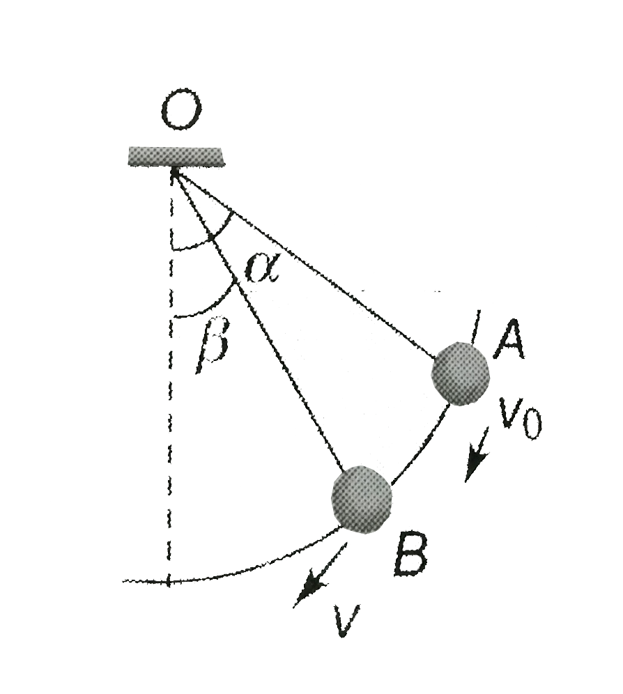
A ball attached to a string length L is oscillating line a simple pendulum. Find v in terms of v0 L α and β.View SolutionIn the circuit diagram shown in Figure, R=10Ω,L=l5H,E=20v,i=2A. This current is decreasing at a rate of −1.0A/s. Find Vab at this instant.
 View Solution
In the circuit as shown, VA−VB=V. The resistance of each wire AB, AC, etc are shown in the figure. Find the current in AC.
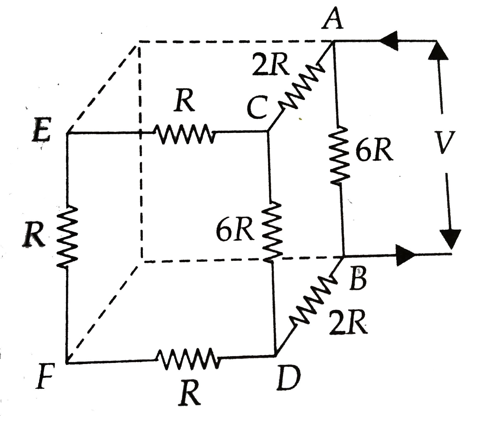 View Solution
In the circuit shown below, the ammeter A reads 5 A and the voltmeter V reads 20 V The correct value of resistance R is
 View Solution
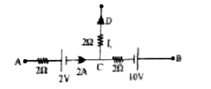
A part of a circuit is shown in figure VR−VC is equal to 12 V. I1 is equal to
 View Solution

