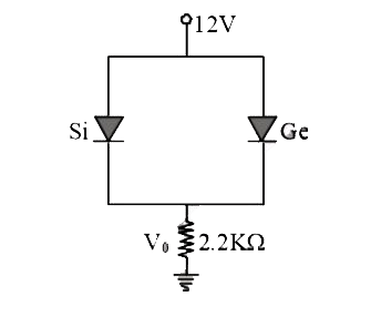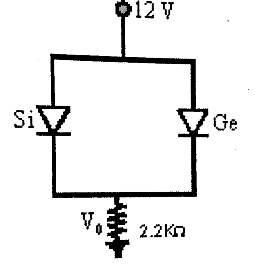
In the circuit shown infigure, voltage V0 is,
11.7 volt
11.3 volt
0
None of these
The correct Answer is:A
Step by step video, text & image solution for In the circuit shown infigure, voltage V_(0) is, by Physics experts to help you in doubts & scoring excellent marks in Class 12 exams.
Updated on:21/07/2023Topper's Solved these Questions
- SEMICONDUCTORSBOOK - BANSALCHAPTER - SEMICONDUCTORSEXERCISE - Exercise-2
24 Videos
- SEMICONDUCTORSBOOK - BANSALCHAPTER - SEMICONDUCTORSEXERCISE - Exercise-3
24 Videos
- MASTER PRACTICE PROBLEMBOOK - BANSALCHAPTER - MASTER PRACTICE PROBLEMEXERCISE - Additional topic
70 Videos
- TEST PAPERSBOOK - BANSALCHAPTER - TEST PAPERSEXERCISE - PHYSICS PART C
14 Videos
Similar Questions
Knowledge Check
In the circuit shown in figure, Voltage V0 is
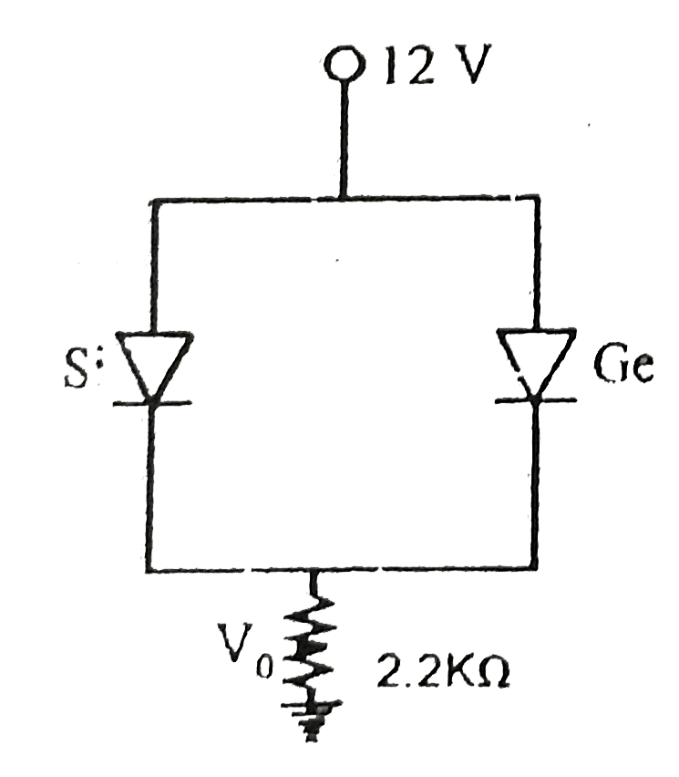 A11.7 voltB11.3 voltC0DNone
In the circuit shown in figure value of VR is
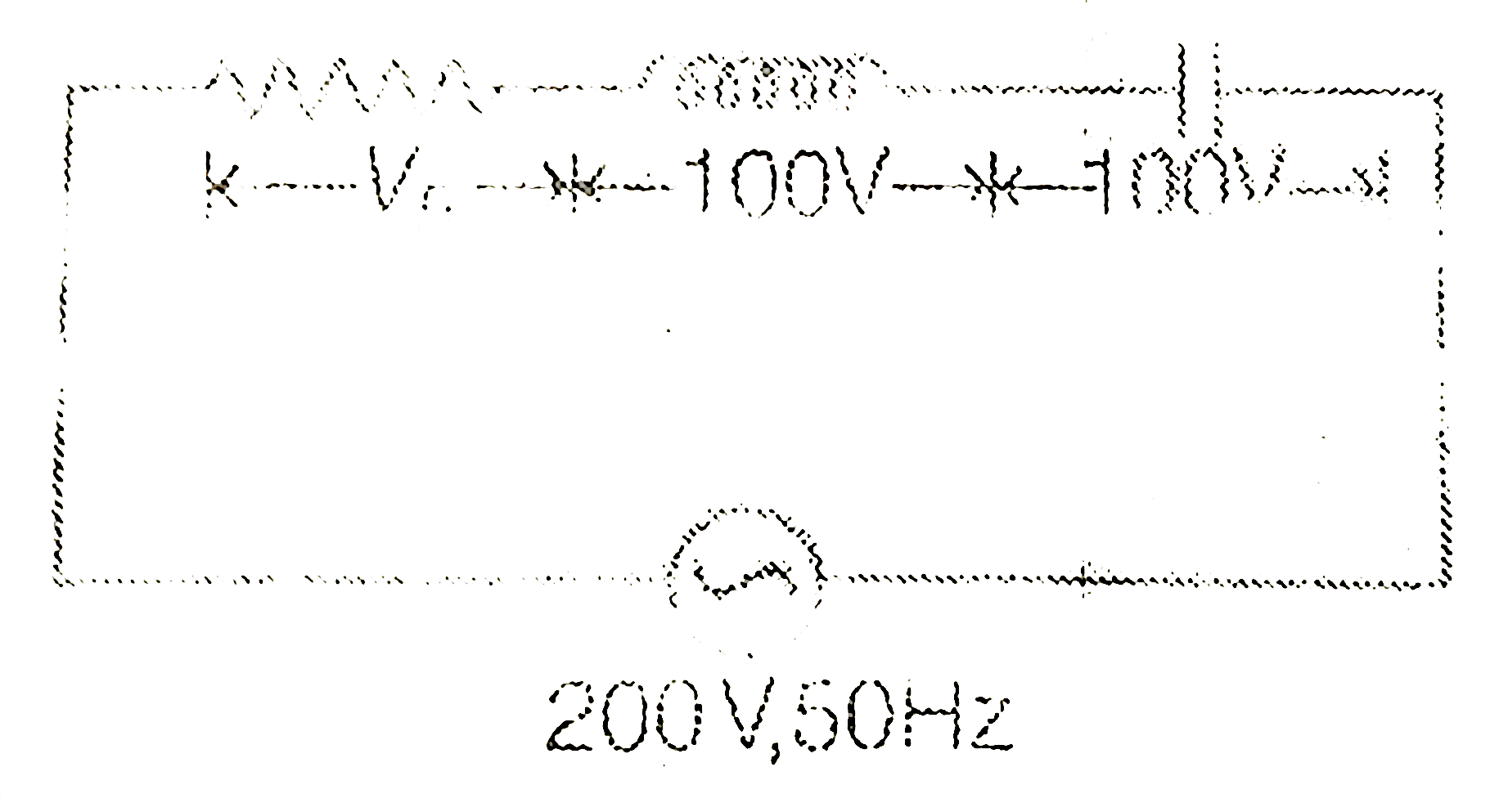 A400VB200VC300VDzero
In the circuit shown in figure the voltage in L and in C are
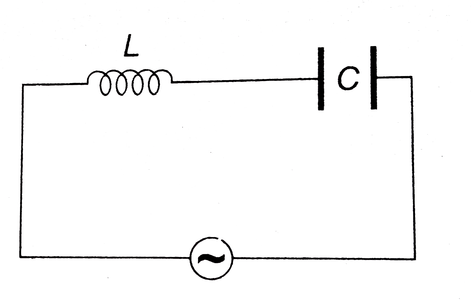 .Ain phaseBout of phase by 90∘Cout of phase by 180∘Din a phase difference which depends upon the values of L C .
In the circuit shown in the figure, the input voltage Vi is 20V,VBE=0 and VCE=0. The values of IB,IC and β are given by:
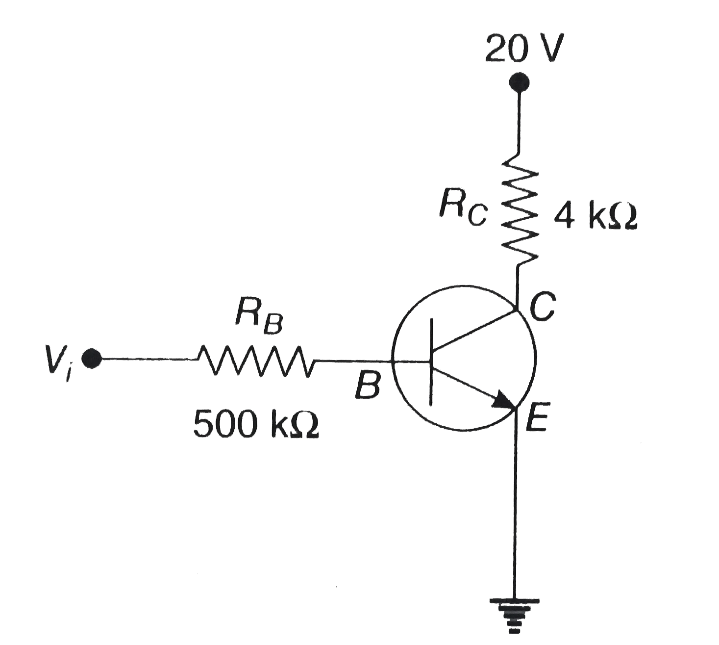
View SolutionIn the circuit shown in the figure, the input voltage Vi is 20V, VBE=0 and VCE=0. The values of IB, IC and β are given by
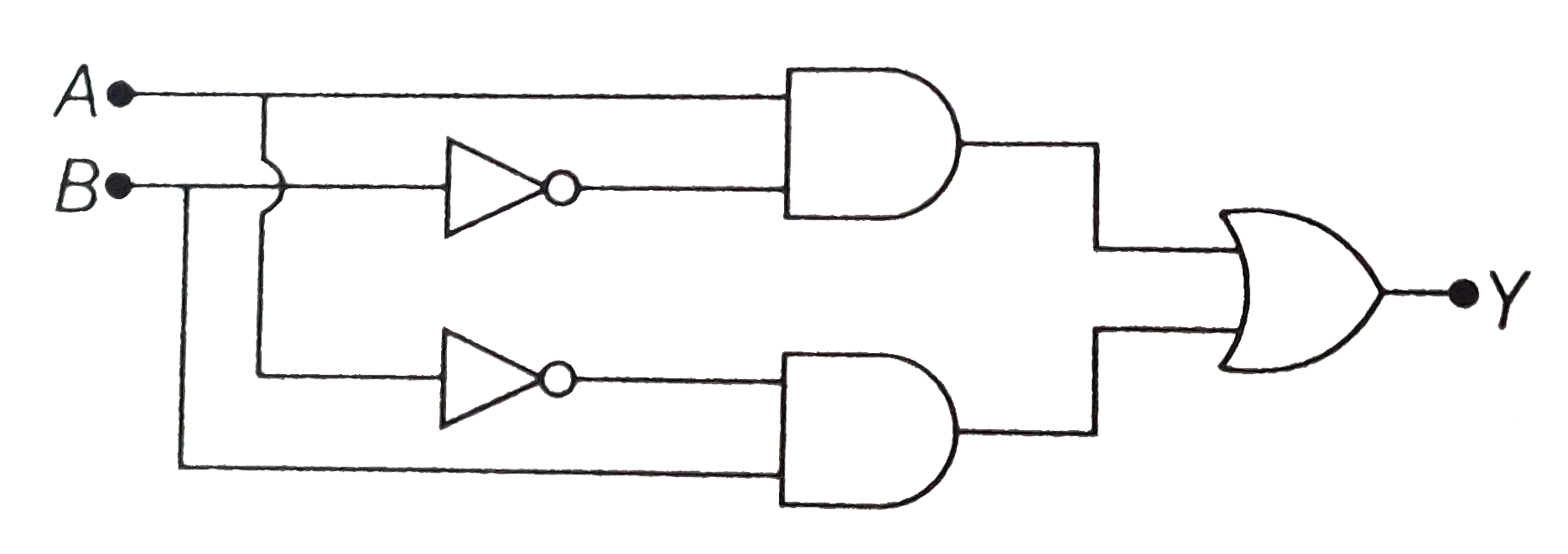
View SolutionIn the circuit shown in the figure, the input voltage Vi is 20V,VBE=0 and VCE=0. The values of IB,IC and β are given by:

View SolutionIn the circuit shown in the figure, the input voltage Vi is 20V,VBE=0 and VCE=0. The values of IB,IC and β are given by:

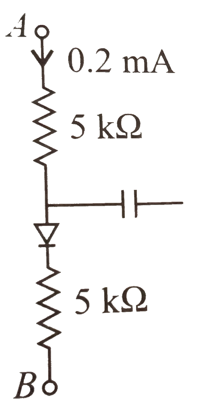
View SolutionIn the circuit shown in figure, if the A diode forward voltage drop is 0.3 V, the voltage difference between A and B is
View Solution

