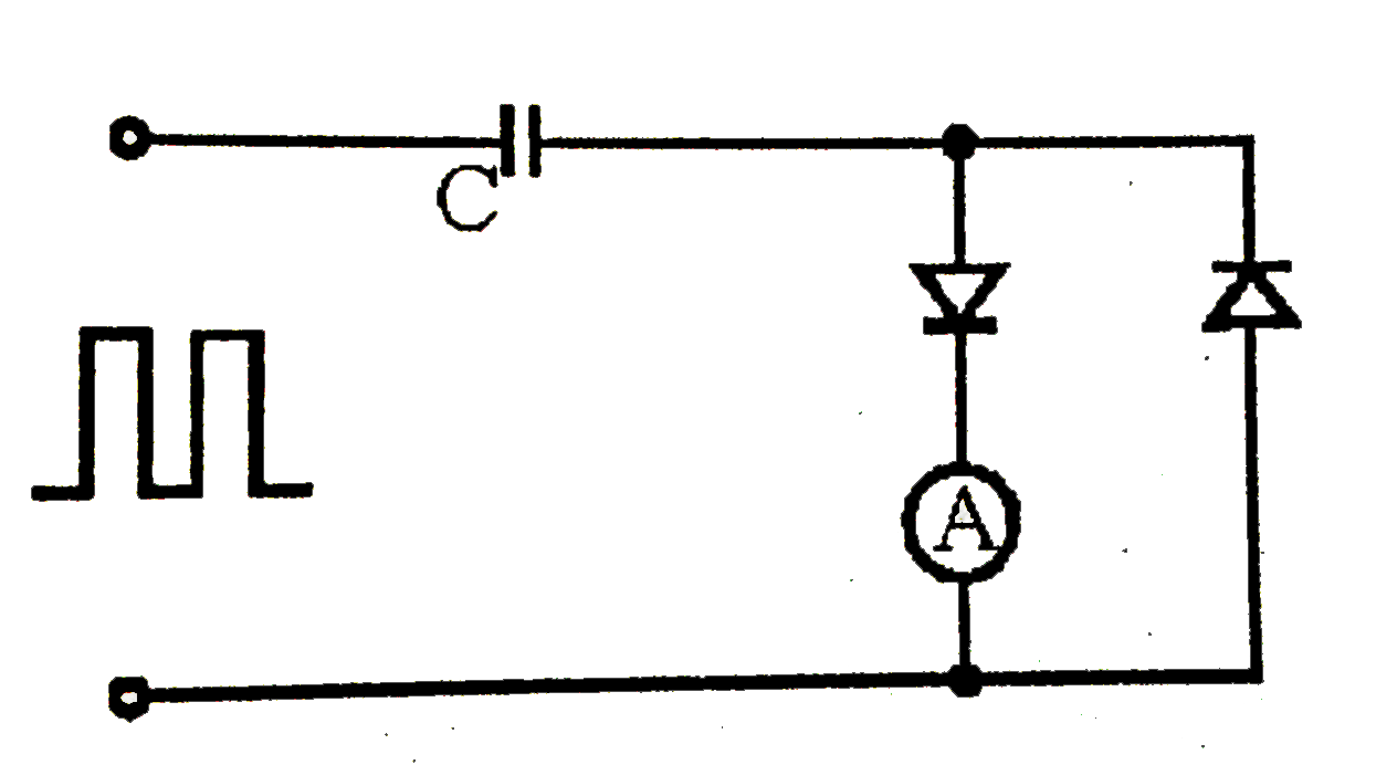
A circuit diagram of a capacitor with two diodes ad an ammeter (Fig) is connected to a source of variable voltage producing rectangular pulses of constant amplitude and frequency. What current does ammeter show? Diodes and ammeter can be considered ideal.
The correct Answer is:(##BSLPHYSCMIE01190_A01##)
Topper's Solved these Questions
- SEMICONDUCTORSBOOK - BANSALCHAPTER - SEMICONDUCTORSEXERCISE - Exercise-4
37 Videos
- SEMICONDUCTORSBOOK - BANSALCHAPTER - SEMICONDUCTORSEXERCISE - Exercise-4 Section-B
6 Videos
- SEMICONDUCTORSBOOK - BANSALCHAPTER - SEMICONDUCTORSEXERCISE - Exercise-2
24 Videos
- MASTER PRACTICE PROBLEMBOOK - BANSALCHAPTER - MASTER PRACTICE PROBLEMEXERCISE - Additional topic
70 Videos
- TEST PAPERSBOOK - BANSALCHAPTER - TEST PAPERSEXERCISE - PHYSICS PART C
14 Videos
Similar Questions
An uncharged capacitor of capacitance is connected in a circuit with two ideal batteries and two ideal ammeters G and G1 as shown. Both switches are initially open. Each option below details a possible pattern of closing the switches, and the consequent readings of the ammeters. Choose the correct option(s):
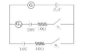
View SolutionAn uncharged capacitor of capacitance is connected in a circuit with two ideal batteries and two ideal ammeters G and G1 as shown. Both switches are initially open. Each option below details a possible pattern of closing the switches, and the consequent readings of the ammeters. Choose the correct option(s):

View Solution
Knowledge Check
A circuit is shown below.
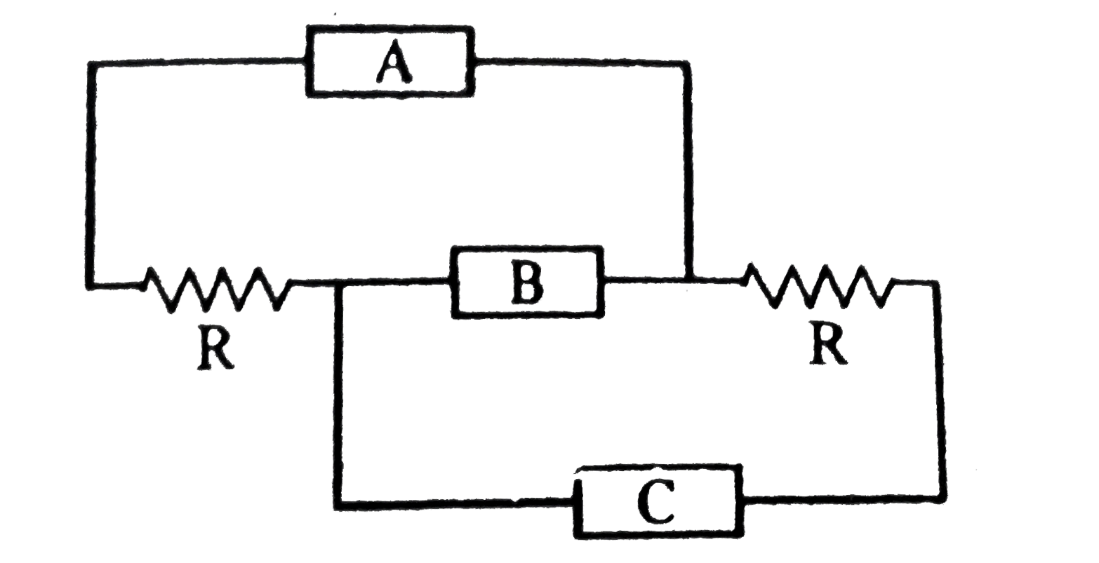
If A is a capacitor, B is an ideal ammeter and C is an ideal battery of voltage V, what is the voltage across the capacitor?AVBV2C2VD0A variable capacitor is connected to an ac source. What effect does decreasing the capacitance have on the reactance and current in this circuit?
AReactance - No change , Current - No changeBReactance - Decreases , Current - No changeCReactance - Increases , Current - IncreasesDReactance - Increases , Current - DecreasesTwo ammeters, 1 and 2 have different internal resistances: r1 (known) and r2 (known). Each ammeter has scale such that the angular deviation of the needle for zero is proportional to the current passing through it. Initially, the ammeters are connected in series to a source of constant voltage. The deviations of the needles of the ammeter are θ1 and θ2, respecitively. The ammeters are then connected in parallel ot the same voltage source. This time, the deviations of the needles are θ'1 and θ'2 respectively. Find r2 in terms of r1,θ1,θ2,θ'1 and θ'2.
Ar1θ1θ'1θ2θ'2Br1θ2θ'1θ1θ'2Cr1θ2θ'2θ1θ'1Dr1θ2θ'2θ1θ'2
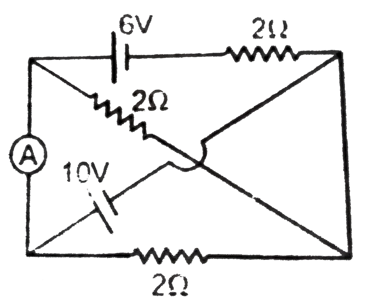
An ideal ammeter is connected in a circuit as shown in circuit diagram. What will be the reading of ammeter (in S.I units)
View SolutionA capacitor of 10μF is connected to an a.c. source of e.m.f. E=220sin100πt. Write the equaiton of instananeous current through the circuit. What will be the reading of a.c. ammeter connected in the circuit ?
View Solution(a) In the following diagram 'S' is a semiconductor . Would
you increase or decrease the value of R to keep the
reading of the ammeter A constant when S is heated ?
Given reason for you answer .
(b) Draw the circuit diagram of photodiode and explain
its working . Draw its I-V characteristics.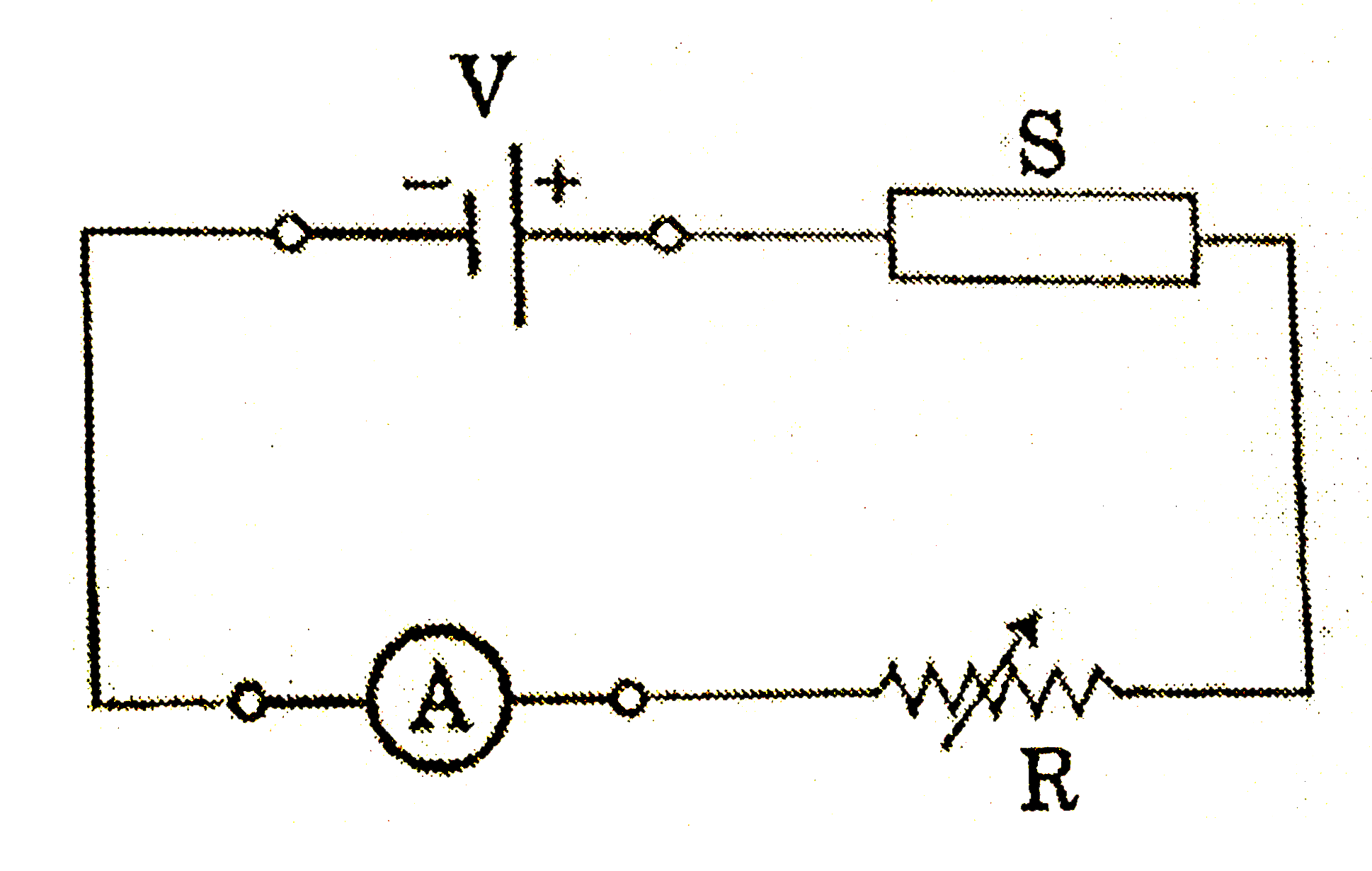
View SolutionAn ideal ammeter is connected in a circuit as shown in circuit diagram. What will be the reading of ammeter (in S.I units)

View SolutionA dc ammeter and a hot wire ammeter are connected to a circuit in series. When a direct current is passed through circuit, the dc ammeter shows 6 A. When ac current flows through circuit, the ac ammeter shows 8A. What will be reading of each ammeter if dc and ac current flow simulataneously through the circuit?
View Solution
