In the circuit shown below (on the left) the resistance and the emf source are both variable. The graph of seven readings of the voltmeter and the ammeter (V and I, respectively) for different setting of resistance and the emf, taken at equal intervals of time Δt, are shown (on the right) by the dots connected by the curve EFGH. Consider the interval resistance of the battery to be negligible and the voltmeter and ammeter to be ideal devices. Take R0=V0/l0.
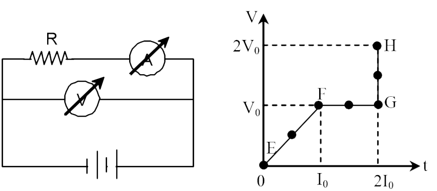
Then the plot of the resistance as a function of time corresponding to the curve EFGH is given by
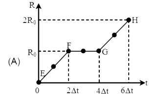
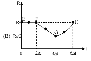
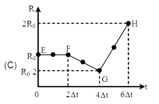
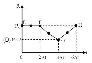
The correct Answer is:D
Step by step video, text & image solution for In the circuit shown below (on the left) the resistance and the emf source are both variable. The graph of seven readings of the voltmeter and the ammeter (V and I, respectively) for different setting of resistance and the emf, taken at equal intervals of time Deltat, are shown (on the right) by the dots connected by the curve EFGH. Consider the interval resistance of the battery to be negligible and the voltmeter and ammeter to be ideal devices. Take R_(0)=V_(0)//l_(0). Then the plot of the resistance as a function of time corresponding to the curve EFGH is given by by Physics experts to help you in doubts & scoring excellent marks in Class 12 exams.
Topper's Solved these Questions
Similar Questions
Knowledge Check
- Question 1 - Select One
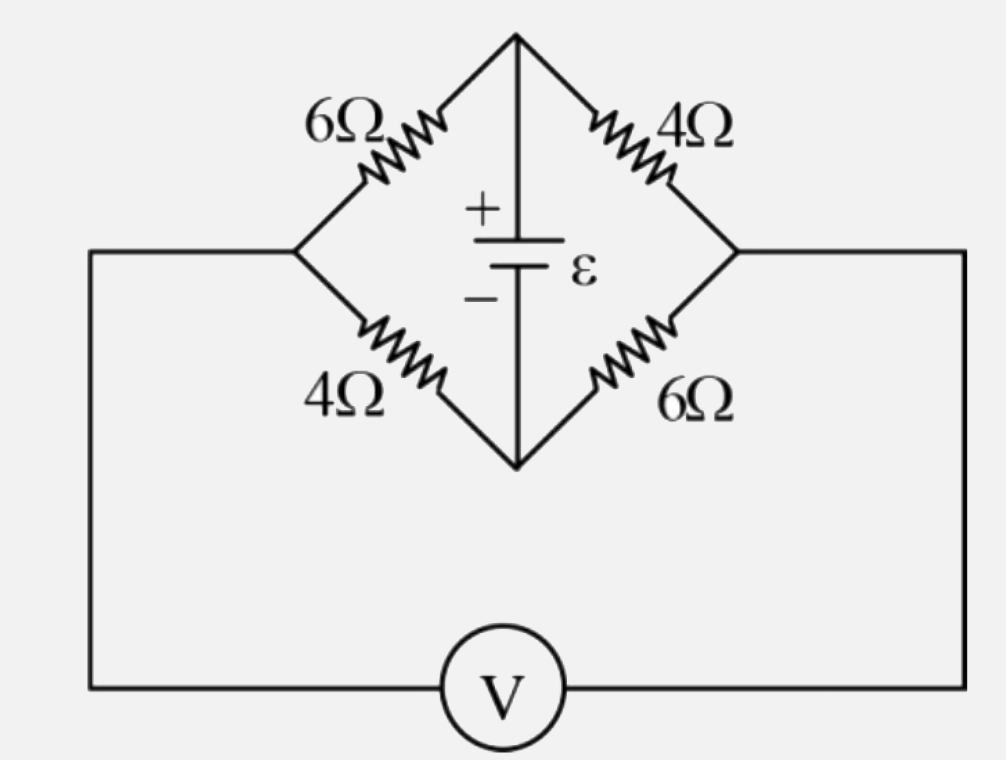
In the circuit shown below, the voltmeter is of large resistance. The E.M.F. of the cell is ε. The reading of the voltmeter is
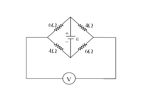 AzeroBε10Cε5Dε2
 - Question 2 - Select One
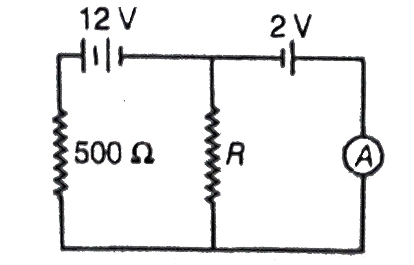
In the circuit shown below, the ammeter reading is zero. Then, the value of the resistance R is
 A50ΩB100ΩC200ΩD400Ω
 - Question 3 - Select One
In the circuit shown below, the ammeter reading is zero. Then, the value of the resistance R is
 A50ΩB100ΩC200ΩD400Ω
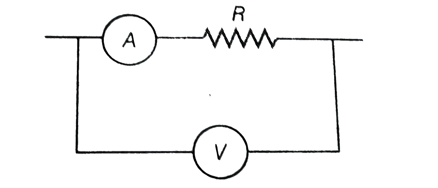
In the circuit shown below, the ammeter and the voltmeter readings are 3 A and 6 V respectively . Then, the value of the resistance R is
 View Solution
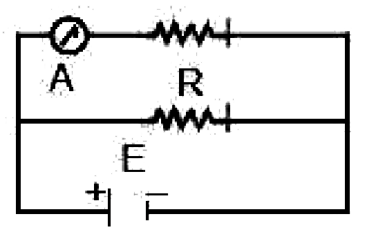
In the circuit shown below, if the value of R is increased then what will be the effect on the reading of ammeter if the internal resistance of cell is negligible-
 View Solution
In the circuit shown below, the ammeter A reads 5 A and the voltmeter V reads 20 V The correct value of resistance R is
 View Solution
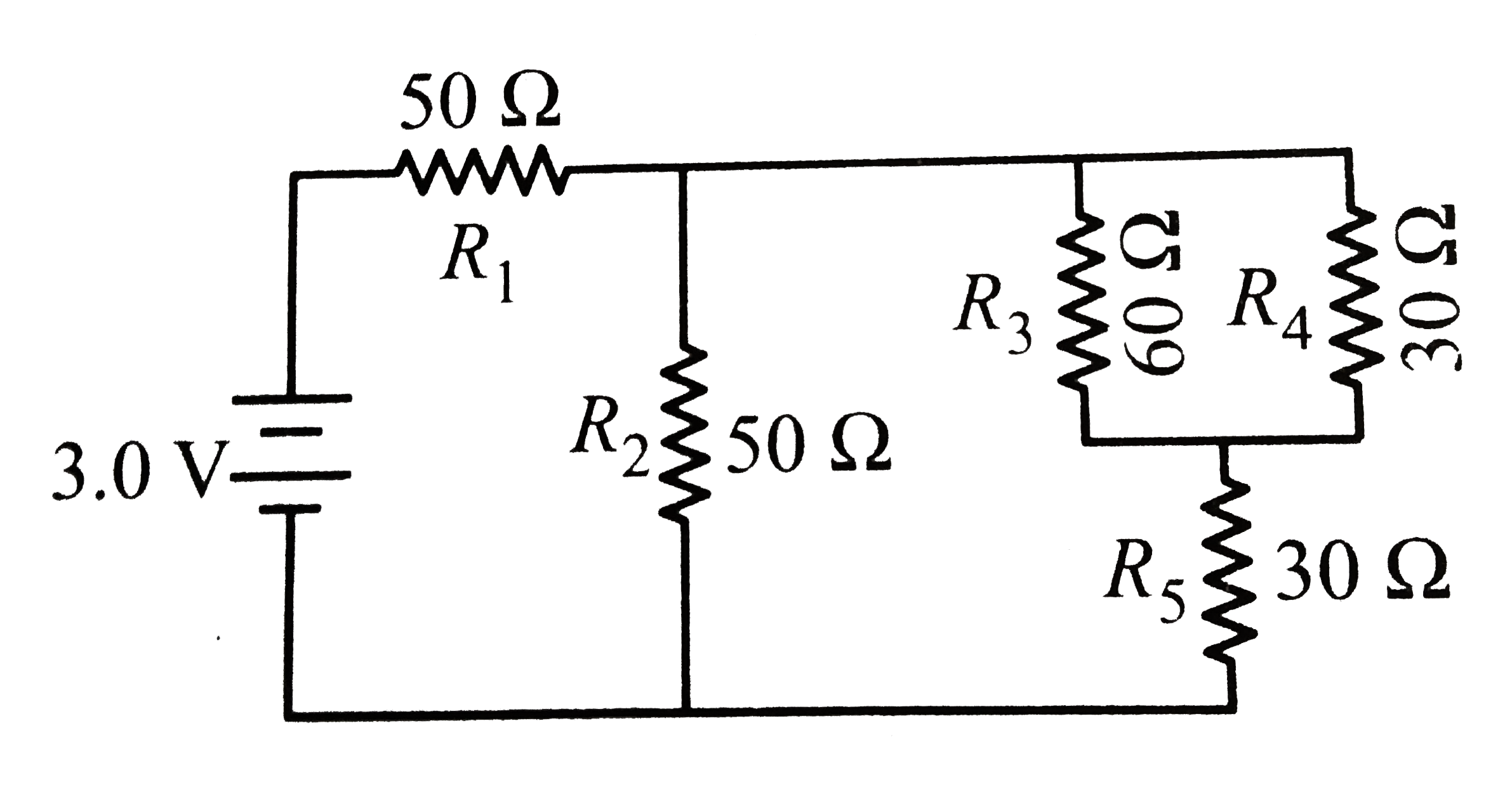
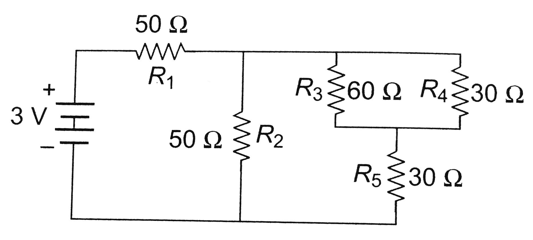
In the circuit shown, the resistances are given in ohms and the battery is assumed ideal with emf equal to 3.0 V.
 View Solution
In circuit shown below, the resistance are given in ohms and the battery is assumed ideal with emf equal to 3 volt The voltage across the resistance R4 is
 View Solution


