The circuit shown in the figure consists of a battery of emf ε=10V , a capacitor of capacitance C=1.0μF and three resistors of value R1=2Ω,R2=2Ω and R3=1Ω, Initially the capacitor is completely uncharged and the switch S is open. The switch S is closed at t=0. Then
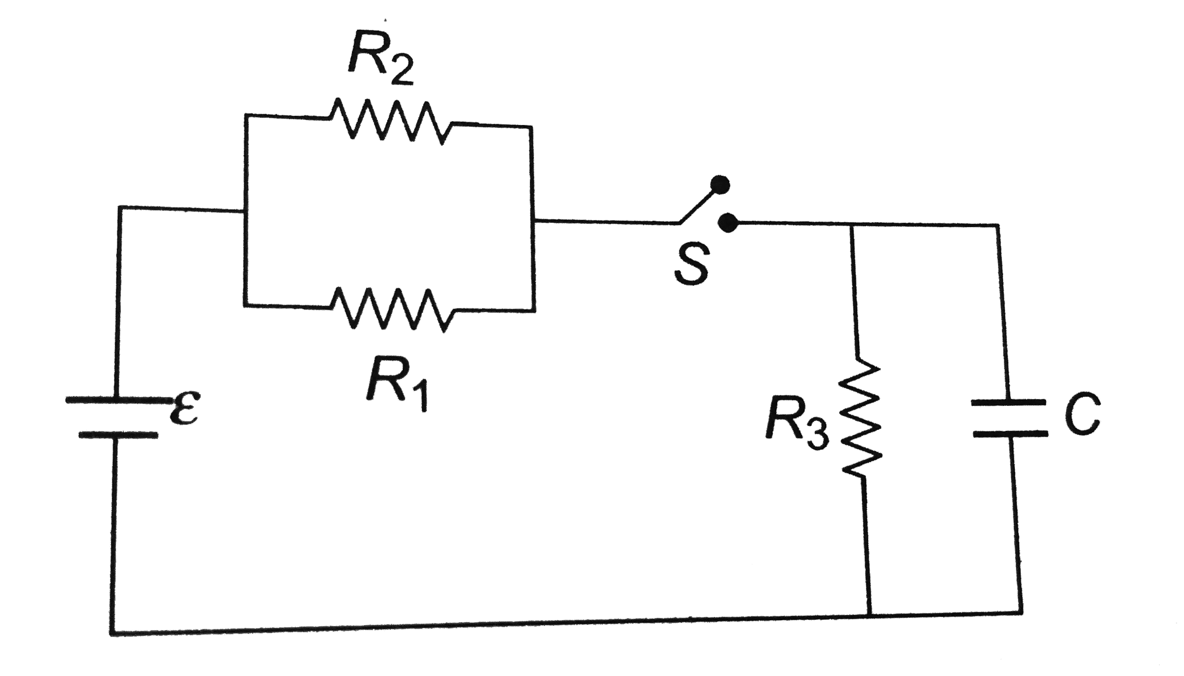
The current through resistor R3 at the moment the switch closed is zero
The current through resistor R3 a long time after the switch closed is 5A
The ratio of current through R1andR−2 is always constant
The maximum charge on the capacitor during the operation in 5μC
The correct Answer is:A, B, C, D
Step by step video & text solution for The circuit shown in the figure consists of a battery of emf epsilon = 10 V , a capacitor of capacitance C = 1.0 mu F and three resistors of value R_(1) = 2 Omega, R_(2) = 2 Omega and R_(3) = 1 Omega, Initially the capacitor is completely uncharged and the switch S is open. The switch S is closed at t = 0. Then by Physics experts to help you in doubts & scoring excellent marks in Class 12 exams.
Updated on:21/07/2023Topper's Solved these Questions
- Capacitance BOOK - MOTIONCHAPTER - Capacitance EXERCISE - EXERCISE -3 LEVEL 1
31 Videos
- Capacitance BOOK - MOTIONCHAPTER - Capacitance EXERCISE - EXERCISE -3 LEVEL II
17 Videos
- Capacitance BOOK - MOTIONCHAPTER - Capacitance EXERCISE - EXERCISE -2
36 Videos
- CALORIMETRY BOOK - MOTIONCHAPTER - CALORIMETRY EXERCISE - EXERCISE - 3 Section - B
4 Videos
- CENTRE OF MASSBOOK - MOTIONCHAPTER - CENTRE OF MASSEXERCISE - Exercise - 4 Level-II
20 Videos
Similar Questions
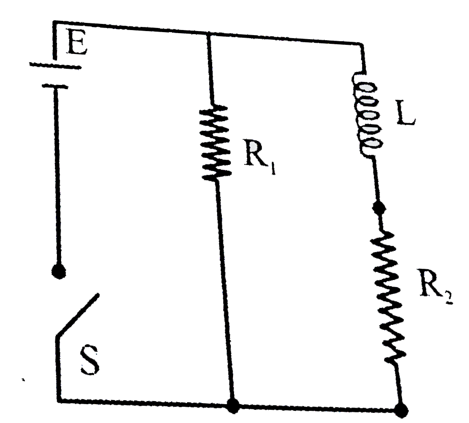
An inductor of inductance L = 400 mH and resistors of resistance R1=2Ω and R2=2Ω are connected to a battery of emf 12 V as shown in the figure. The internal resistance of the battery is negligible. The switch S is closed at t=0. The potential drop across L as a function of time is
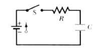
View SolutionSwitch S in Fig. 27-46 is closed at time t= 0, to begin charging an initially uncharged capacitor of capacitance C=49.0μF through a resistor of resistance R=32.0Ω. At what time is the potential across the capacitor equal to that across the resistor?
View Solution
Knowledge Check
The circuit consists of two resistors (of resistance R1=20Ω and R2=10Ω), a capacitor (of capacitance C=10μF) and two ideal cells. In the circuit shown the capacitor is in steady state and the switch S is open
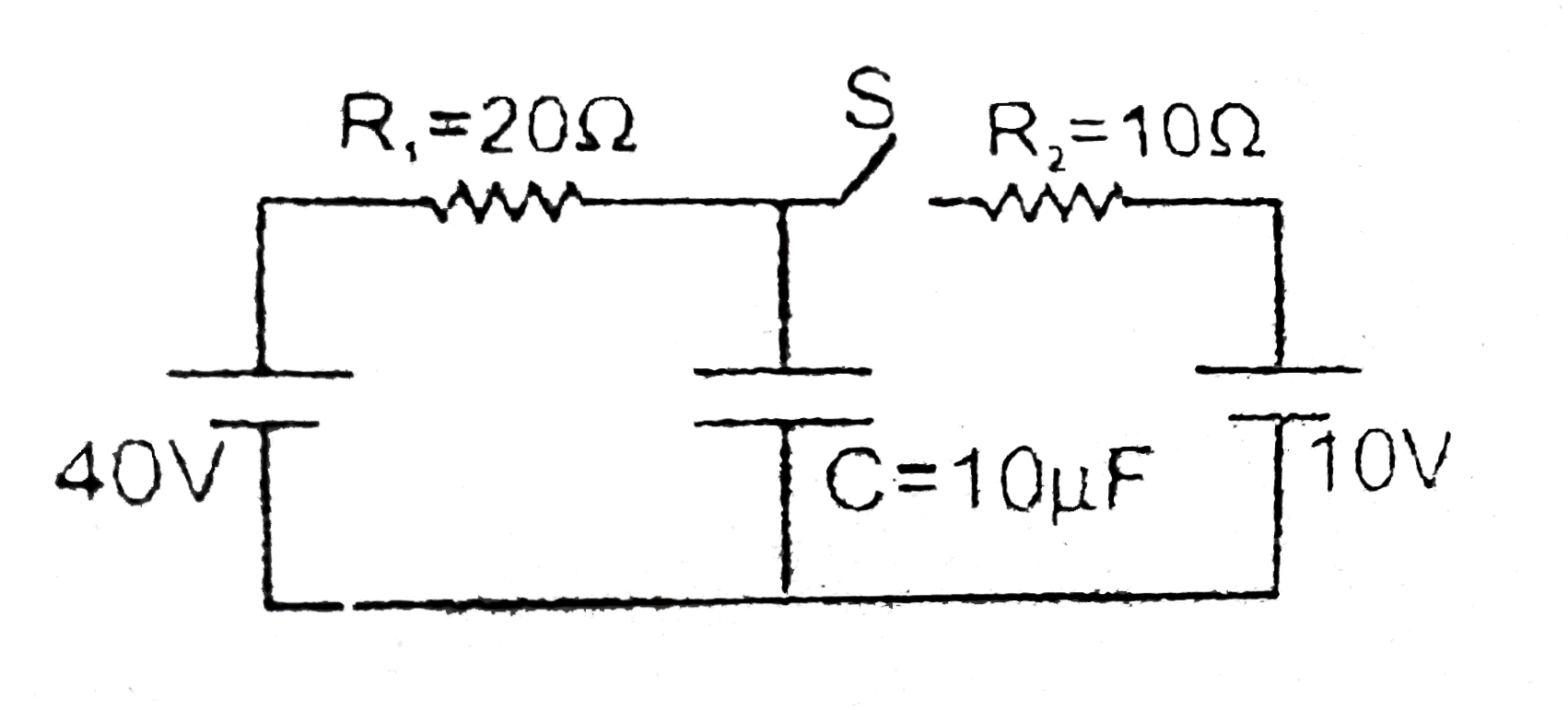
The current through the resistor R2 just after the switch S is closed is :A1 ampereB2 ampereC3 ampereD4 ampereIn the circuit shown below E1=4.0V,R1=2Ω,E2=6.0V,R2=4Ω and R3=2Ω. The current I1 is
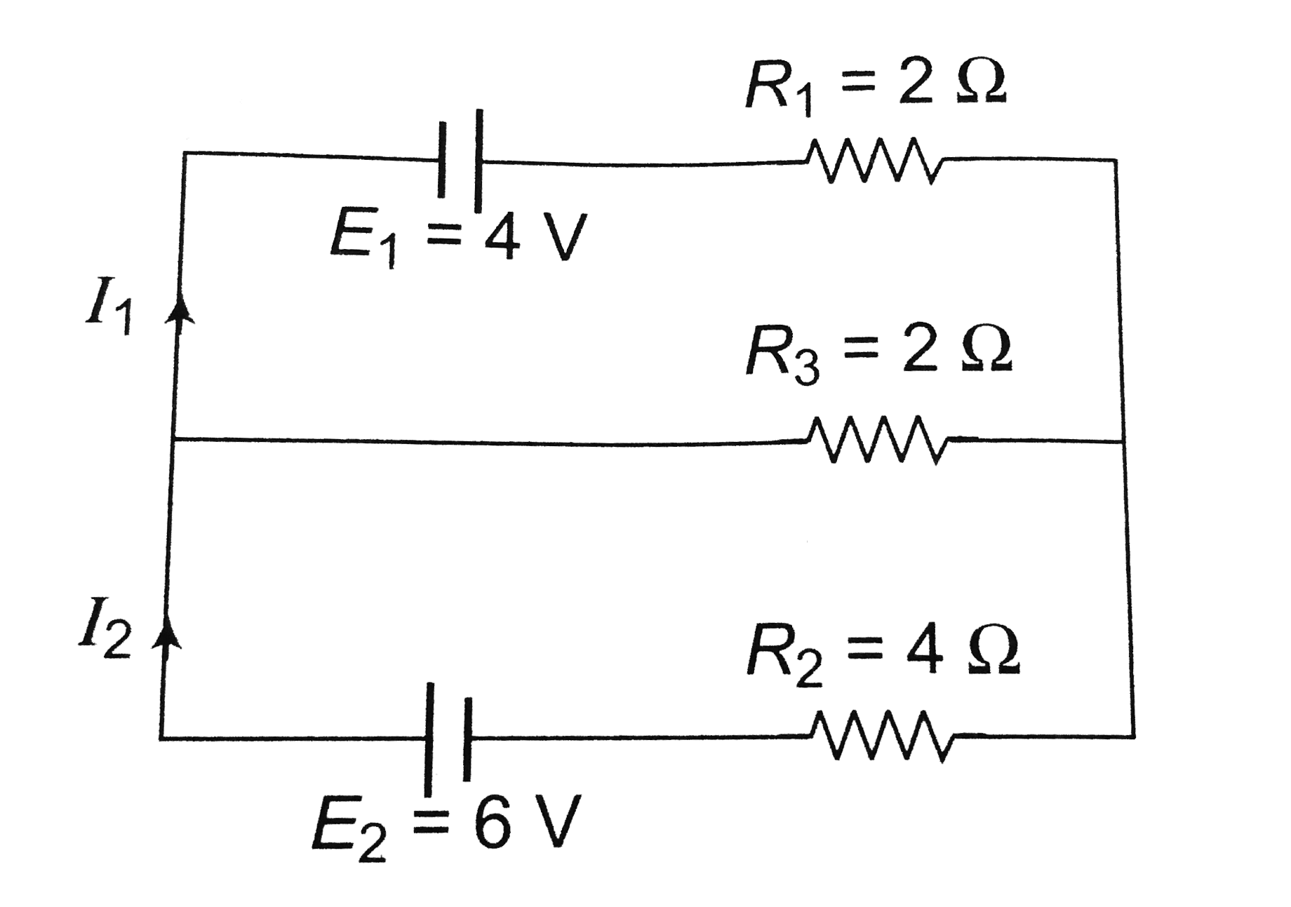 A1.6AB1.8AC1.25AD1.0A
The circuit consists of two resistors (of resistance R1=20Ω and R2=10Ω), a capacitor (of capacitance C=10μF) and two ideal cells. In the circuit shown the capacitor is in steady state and the switch S is open
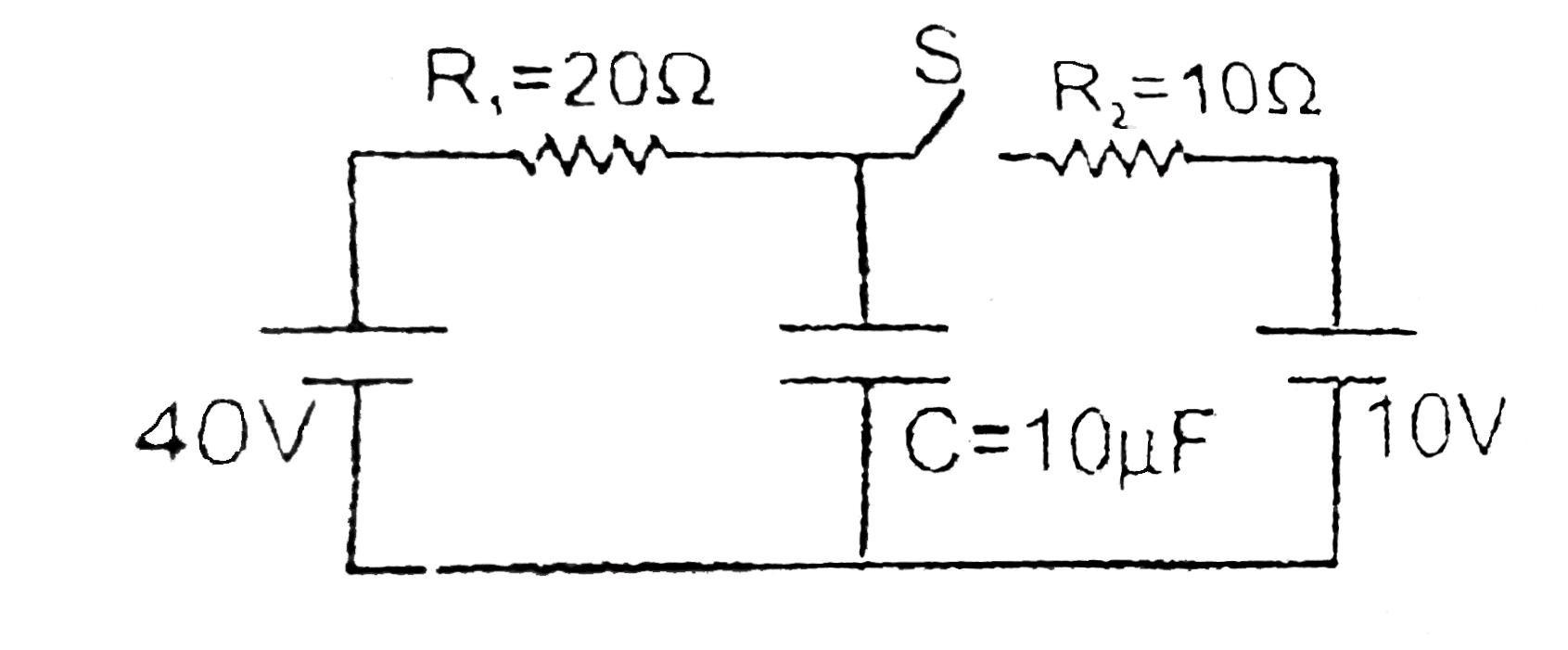
The charge on capacitor in steady state with switch S closed.A100μCB200μCC300μCD400μC
The circuit consists of two resistors (of resistance R1=20Ω and R2=10Ω), a capacitor (of capacitance C=10μF) and two ideal cells. In the circuit shown the capacitor is in steady state and the switch S is open
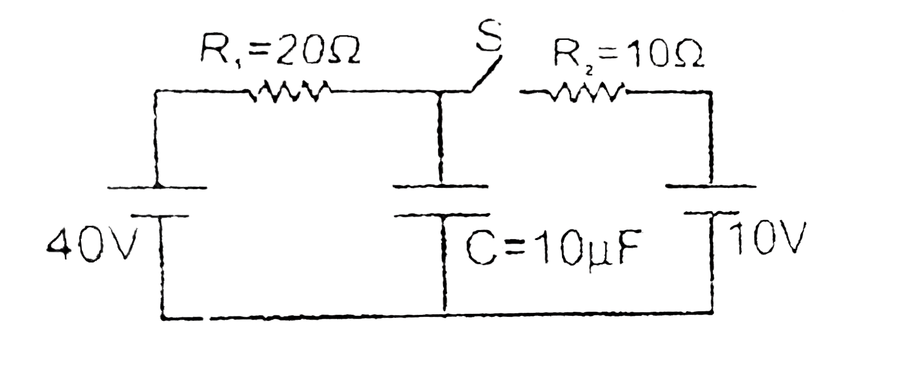
the circuit is in steady state with switch S closed. Now the switch S is opened. Just after the switch S is opened. the current through resistance R1 is
View SolutionAn inductor of inductance L = 400 mH and resistors of resistance R1=2Ω and R2=2Ω are connected to a battery of emf 12V as shown in the figure.The internal resistance of the battery is negligible.The switch S is closed at t = 0.The potential drop across L as a function of time is
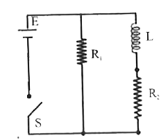
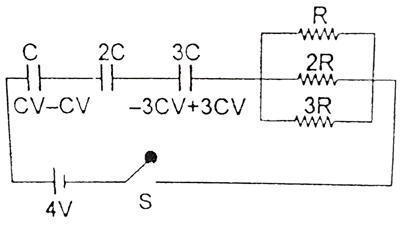
View SolutionThree capacitors (of capacitances C, 2C and 3C) and three resistors (of resistance R, 2R and 3R) are connected with a battery and switch S as shown in the figure. When switch S is open, charges on the capacitors are shown. Switch S is closed at t=0sec. The time constant of the circuit will be
View SolutionAn inductor of inductance L = 400 mH and resistors of resistance R1=2Ω and R2=2Ω are connected to a battery of emf 12 V as shown in the figure. The internal resistance of the battery is negligible. The switch S is closed at t=0. The potential drop across L as a function of time is

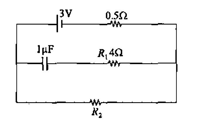
View SolutionAlμFcapacitor is connected in the circuit shown below. The EMF of the cell is 3V and internal resistance is 0.50Ω. The resistors R1andR2 have values 4Ωand1Ω respectively. The charge on the capacitor in steady state is :
View Solution
