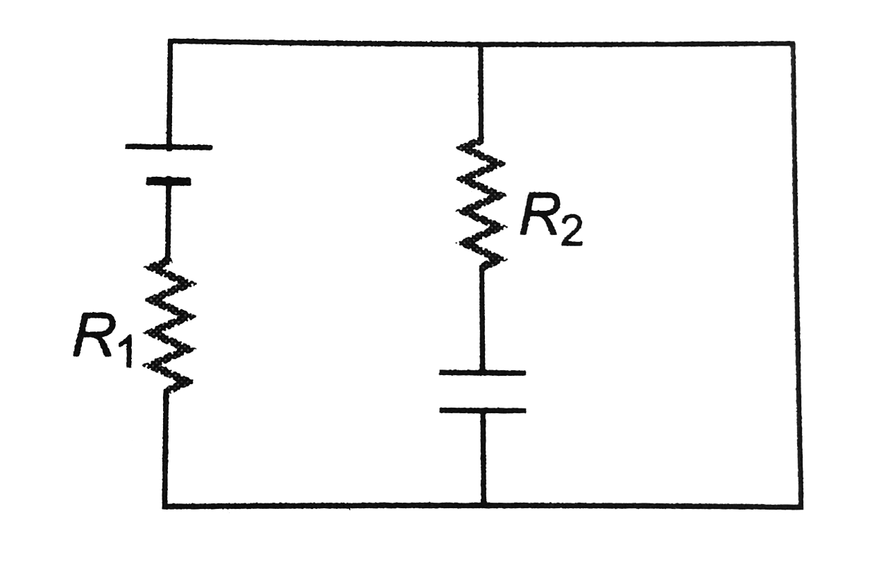
In the circuit shown in figure C1=C2=2μF. Then charge stored in
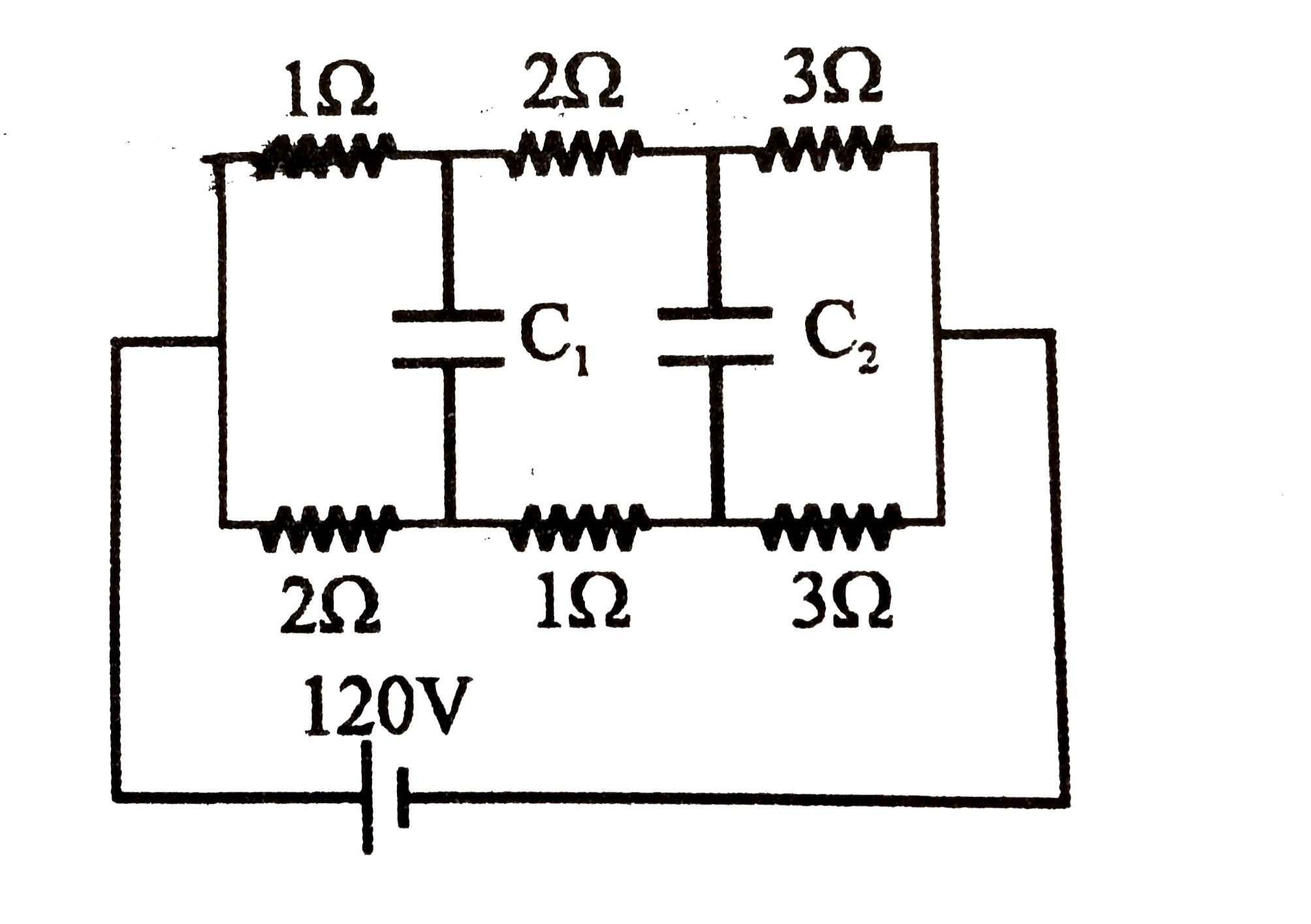
Capacitor C1 is zero
Capacitor C2 is zero
both capacitor is zero
capacitor C1is40μC
The correct Answer is:B, D
Step by step video, text & image solution for In the circuit shown in figure C_(1) =C_(2) = 2muF. Then charge stored in by Physics experts to help you in doubts & scoring excellent marks in Class 12 exams.
Updated on:21/07/2023Topper's Solved these Questions
- Capacitance BOOK - MOTIONCHAPTER - Capacitance EXERCISE - EXERCISE -3 LEVEL 1
31 Videos
- Capacitance BOOK - MOTIONCHAPTER - Capacitance EXERCISE - EXERCISE -3 LEVEL II
17 Videos
- Capacitance BOOK - MOTIONCHAPTER - Capacitance EXERCISE - EXERCISE -2
36 Videos
- CALORIMETRY BOOK - MOTIONCHAPTER - CALORIMETRY EXERCISE - EXERCISE - 3 Section - B
4 Videos
- CENTRE OF MASSBOOK - MOTIONCHAPTER - CENTRE OF MASSEXERCISE - Exercise - 4 Level-II
20 Videos
Similar Questions
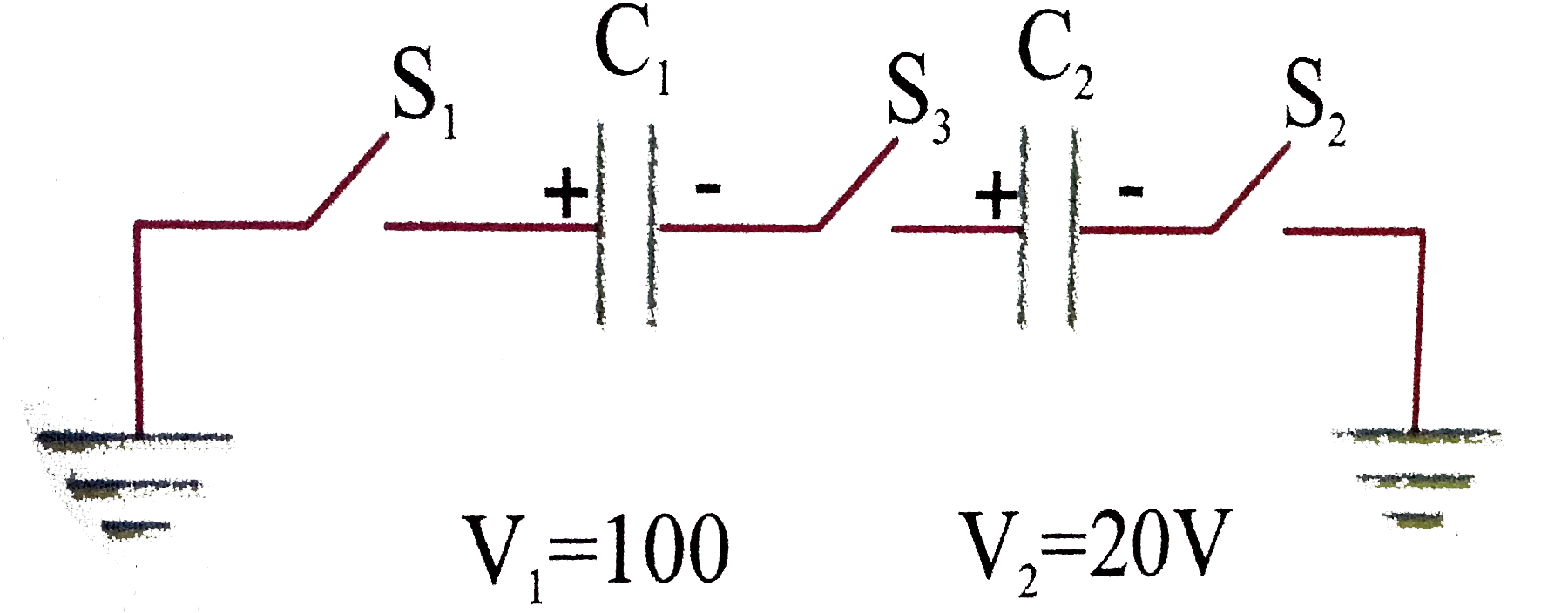
In the circuit shown in figure C1=1μF and C2=2μF. The capacitor C1 is charged to 100V and the capacitor C2 is charged to 20V. After charging then are connected as shown. When the switches S1,S2 and S3 are closed, the charged flowing through S1 is
 .
.
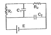
View SolutionIn the circuit shown in figure, R(1)=1Ω,R2=2Ω,C1=1μF,C2=2μF and E=6V. Calculate charge on each capacitor in steady state
View Solution
Knowledge Check
In the circuit shown in figure, C=6μF The charge stored in capacitor of capacity C is
 AzeroB90μCC40μCD60μC
In the circuit shown in figure C1=2C2. Capacitance C1 is charged to a potential of V. The current in the circuit just after the switch S is closed is
 AzeroB2VRCinfiniteDV2R
In the circuit shown in, C=6μF. The charge stored in the capacitor of capacity C is
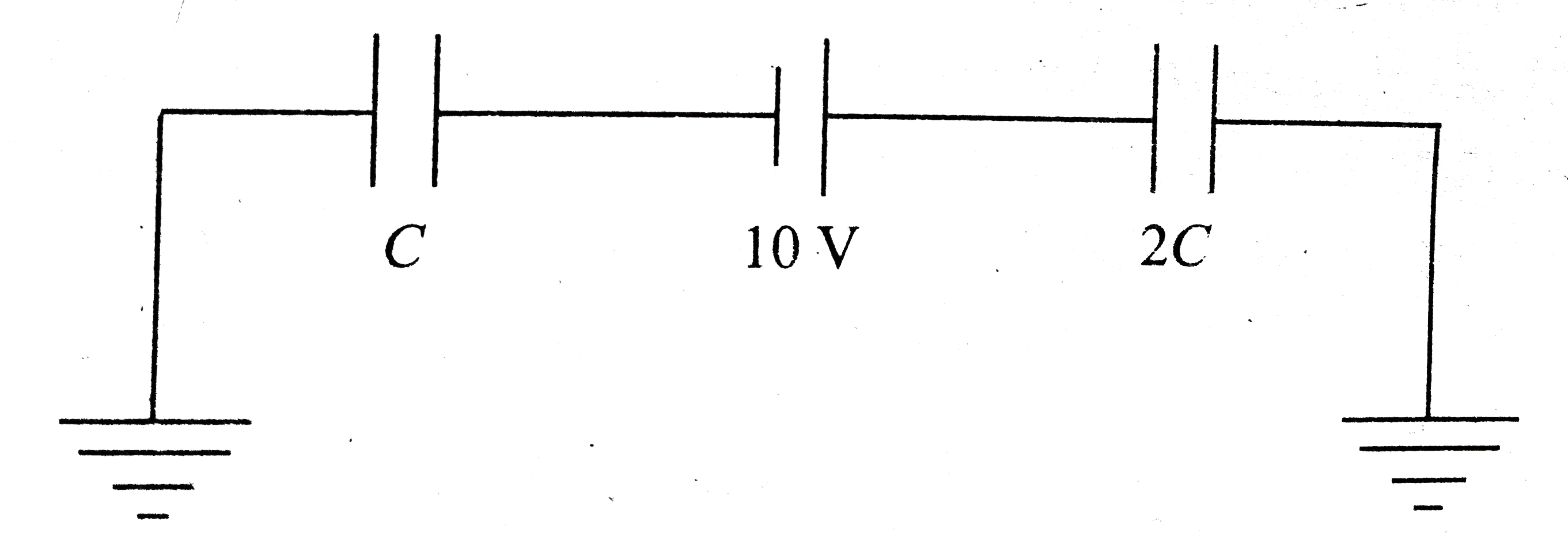 . AzeroB90μCC40μCD60μC
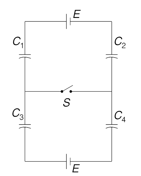
In the circuit shown in Figure E=12V,C1=4μF,C2=2μF,C3=6μFandC4=3μF
Find the heat produced in the circuit after switch S is shorted.
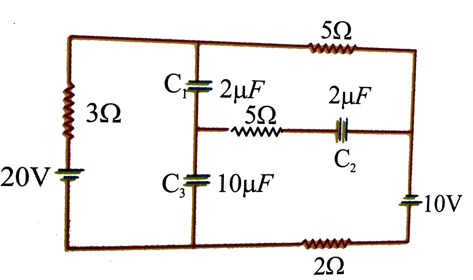
View SolutionIn the circuit shown in figure. The charge on capacitor C2 in steady state is 10xμC. Find the value of x.
 .
.
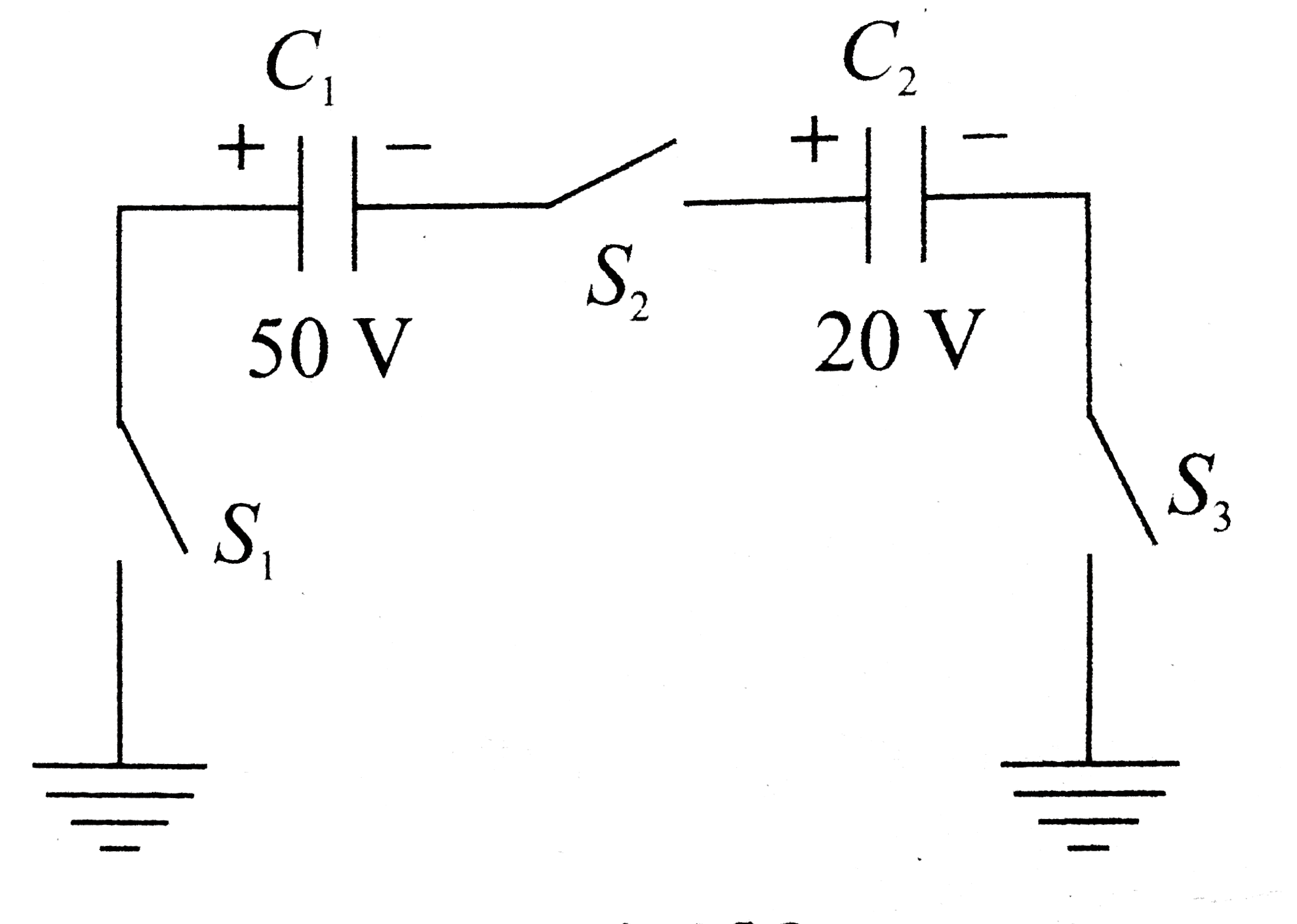
View SolutionIn the circuit shown, C1=C2=2μF. Capacitor C1 is charged to 50V and C1 is charge to 20V. After charging they are connected as shown. When S1,S2, and S3, are clsosed,
 .
.
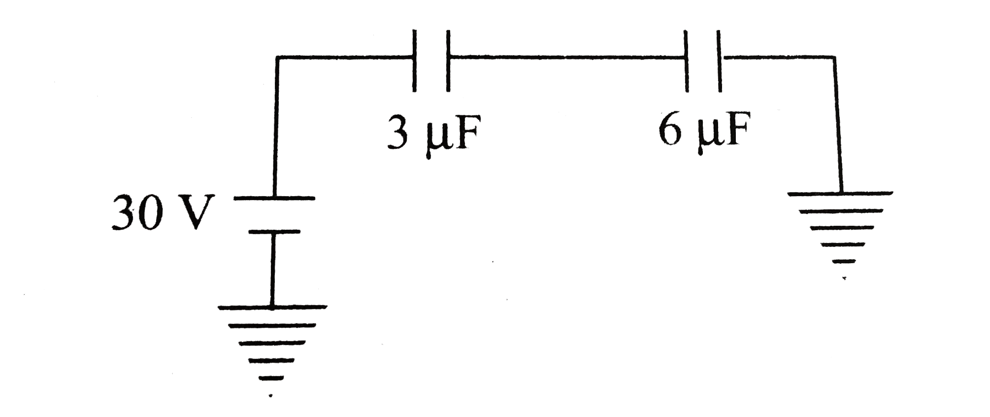
View SolutionIn the circuit shown in figure, the charge stored on a capacitor of capacitance 3μF is
View SolutionAssertion: In the circuit shown in figure no charge will stored in the capacitor.
Reason: Current through R2 will be zero.
View Solution
