In the circuit as shown in the figure, switch S is added at t=0. Then:
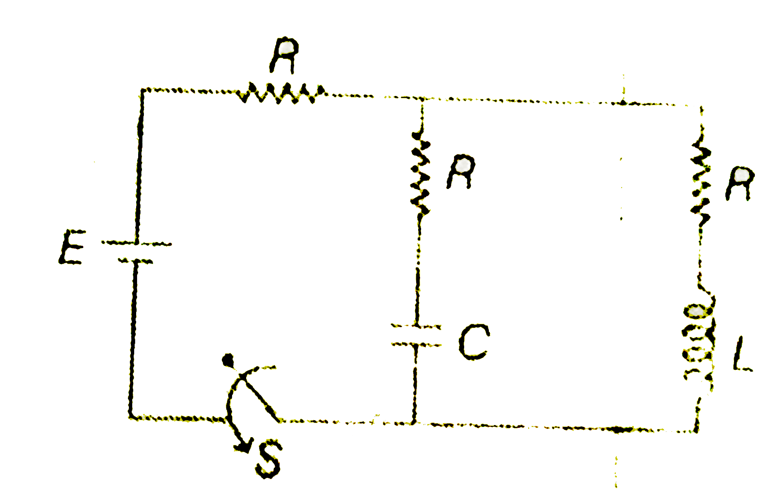
after a long time interval potential differences across capacitor and inductor will be equal
after a long time interval charge on a capacitor will be EC
after a long time interval curent in the inductory will be E/R
after a long time interval current through battery willl be same as the curren through it initially
The correct Answer is:D
Step by step video, text & image solution for In the circuit as shown in the figure, switch S is added at t=0. Then: by Physics experts to help you in doubts & scoring excellent marks in Class 12 exams.
Similar Questions
In the circuit shown in figure switch S is closed at time t=0
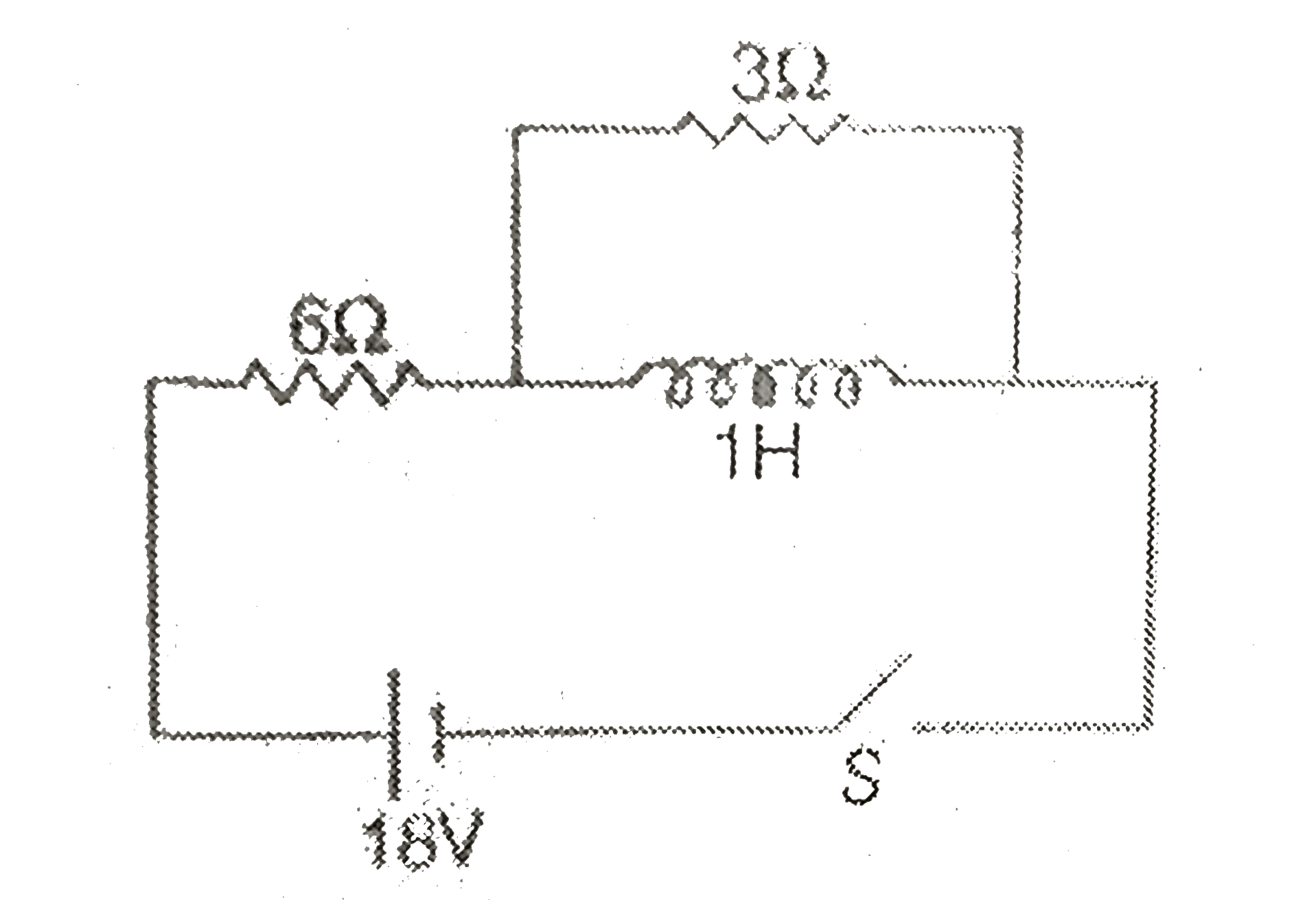
Current I from the battery at time t is given byView SolutionIn the circuit shown in figure switch S is closed at time t=0
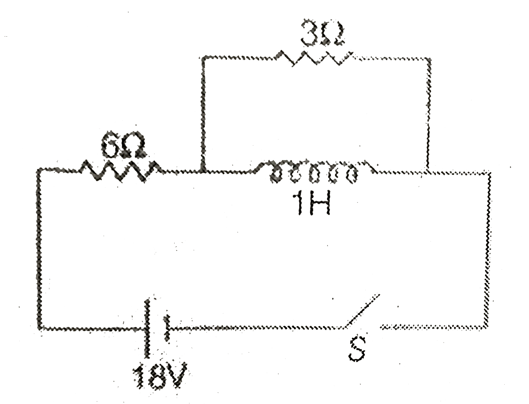
Takin left to right current through the indcutor as apositive current, current through inductor varies with time asView Solution
Knowledge Check
- Question 1 - Select One or More
In the circuit shown in the figure, switch S is closed at time t=0. Select the correct statements.
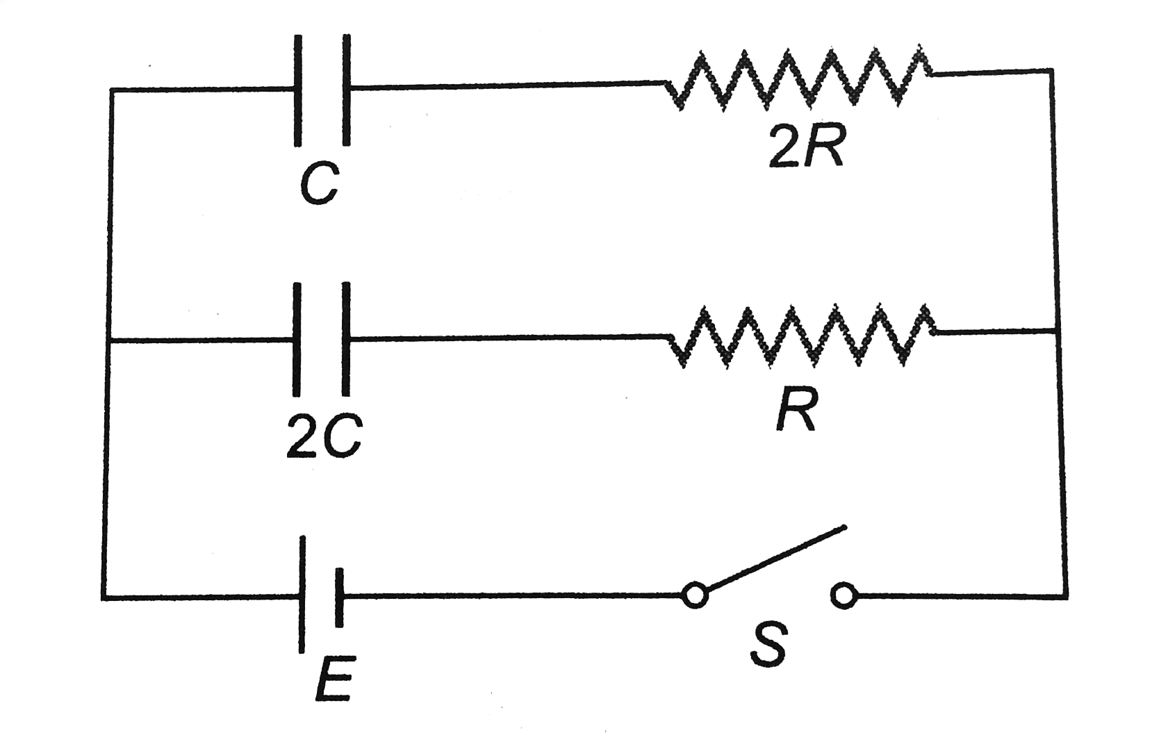 ARate of increase of charge is same in both the capacitorsBRatio of charge stored in capacitors C and 2C at any time t would be 1:2CTime constants of both the capacitors are equalDSteady state chares on capacitors C and 2C are in the ratio of 1:2
 - Question 2 - Select One
In the circuit shown in figure switch S is closed at time t=0. The charge which passes through the battery in one time constant is
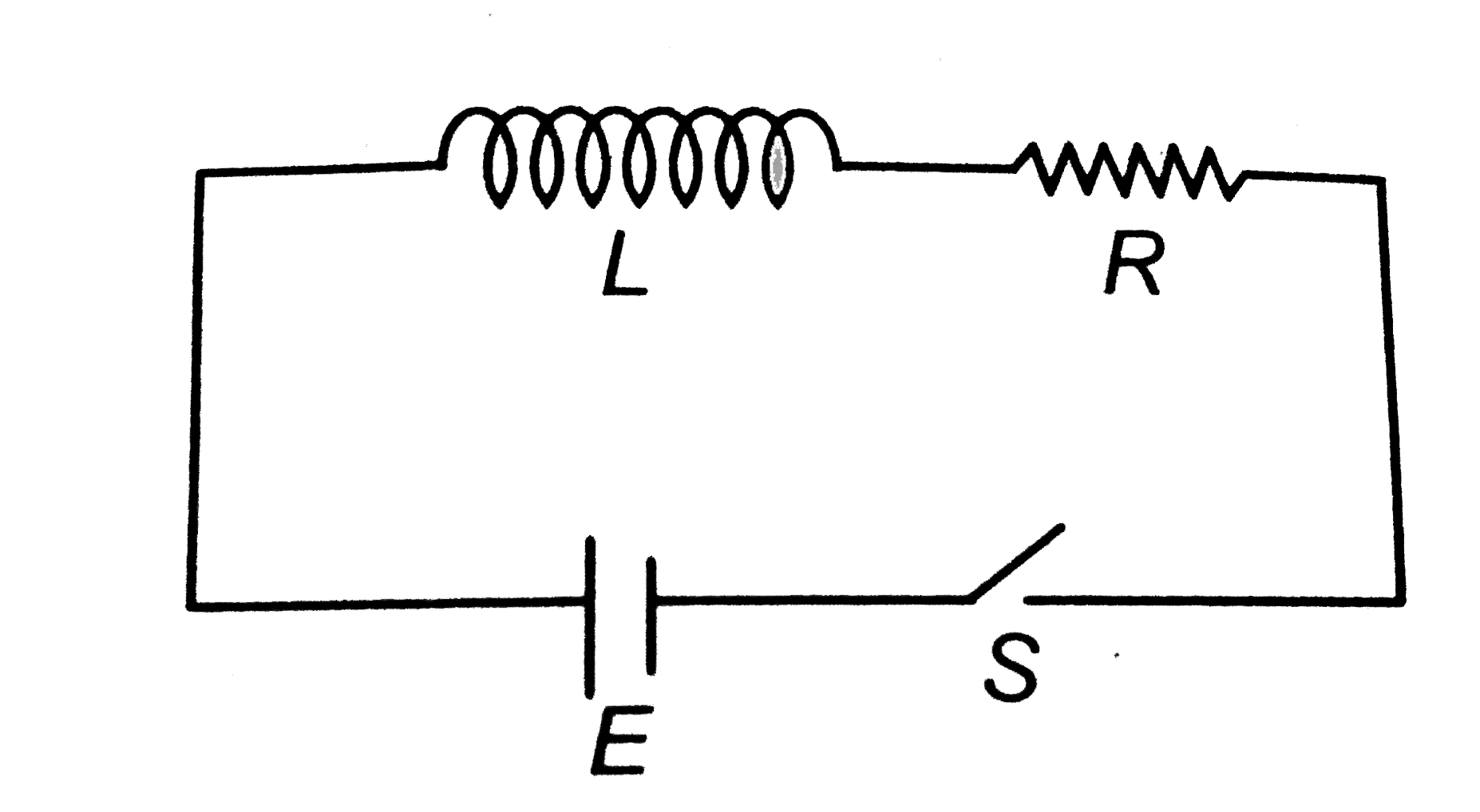 AeR2ELBE(LR)CELeR2DeLER
 - Question 3 - Select One or More
In the circuit as shown in figure the switch is closed at t=0.
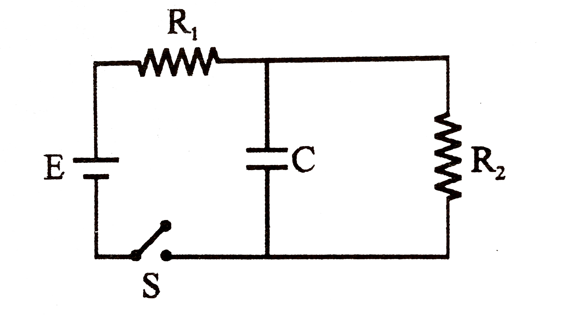
At the instant of closing the switchAthe battery delivers maximum currentBno current flows through CCvoltage drop across R2 is zeroDthe current through the battery decreases with time finally becomes zero
In the circuit as shown in figure the switch is closed at t=0.
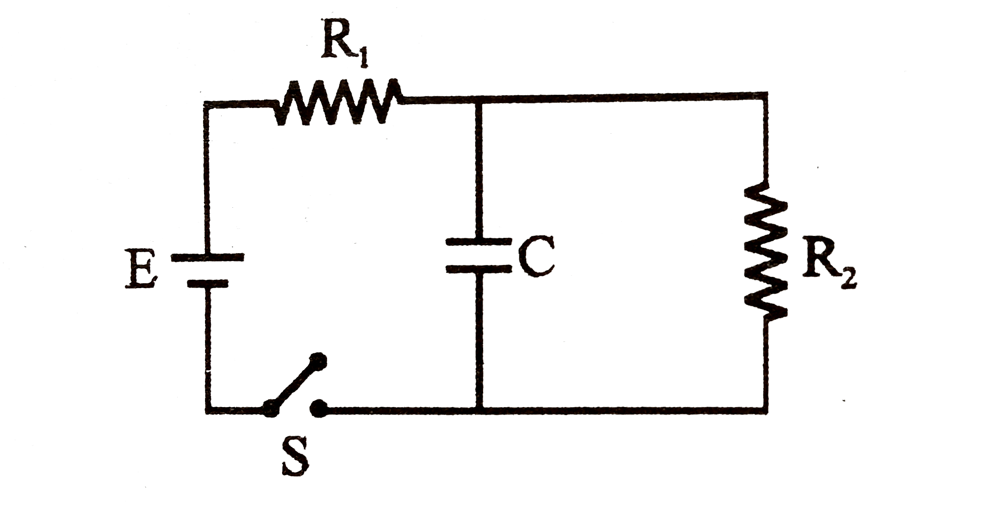
A long time after closing the switchView SolutionIn the circuit shown in figure switch S is closed at time t=0
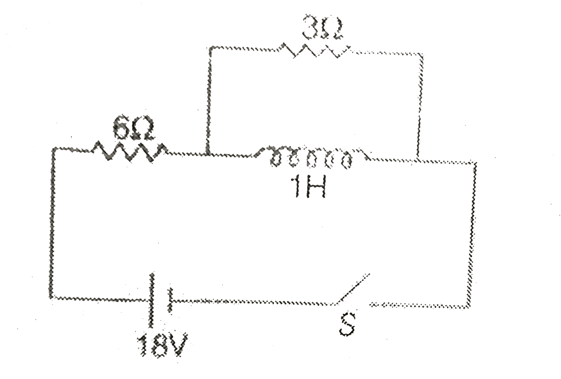
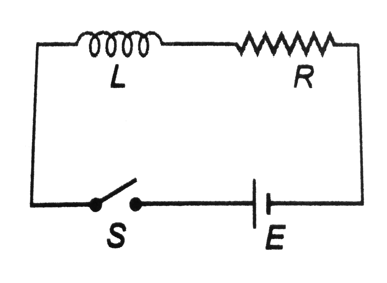
Potential difference across 3Ω resistance at time t is given byView SolutionIn the circuit shown in figure, the switch S is closed at t=0. If VL is the voltge induced across the inductor and i is the instantaneous current, the correct variation of VL versus is given by
 View Solution
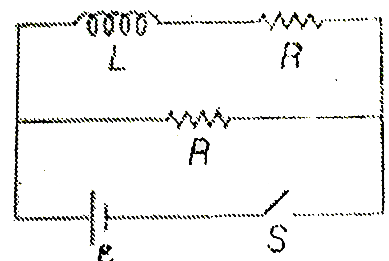
In the circuit shown in figure switch S is closed at time t=0, which statement is true after one time constant of L-R circuit?
 View Solution
In the circuit shown in figure switch S is closed at time t=0
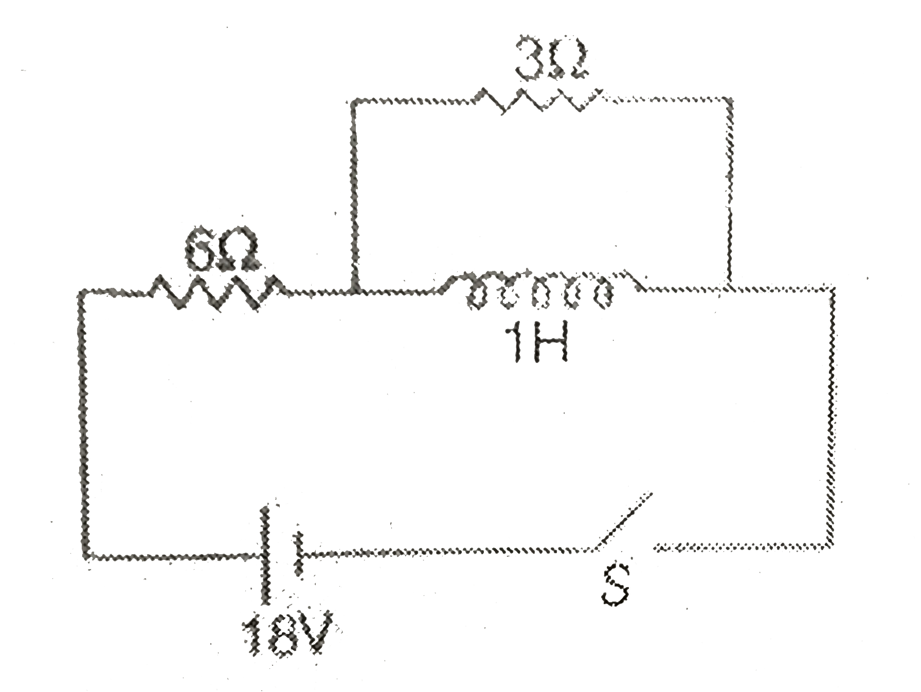
At what time current through 3Ω resistance and 1H inductor are equal?View Solution

