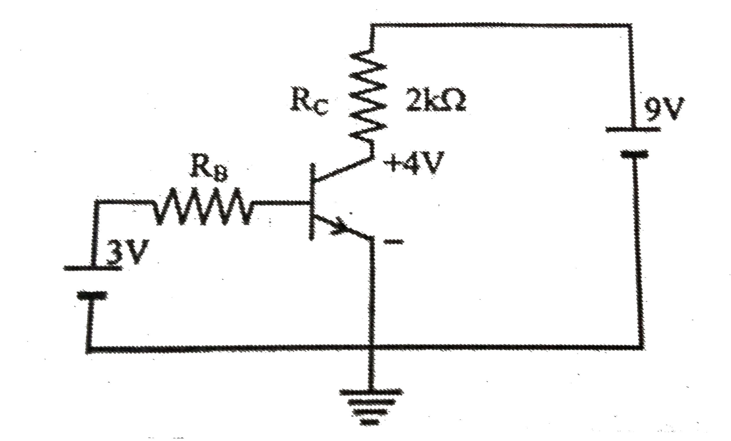
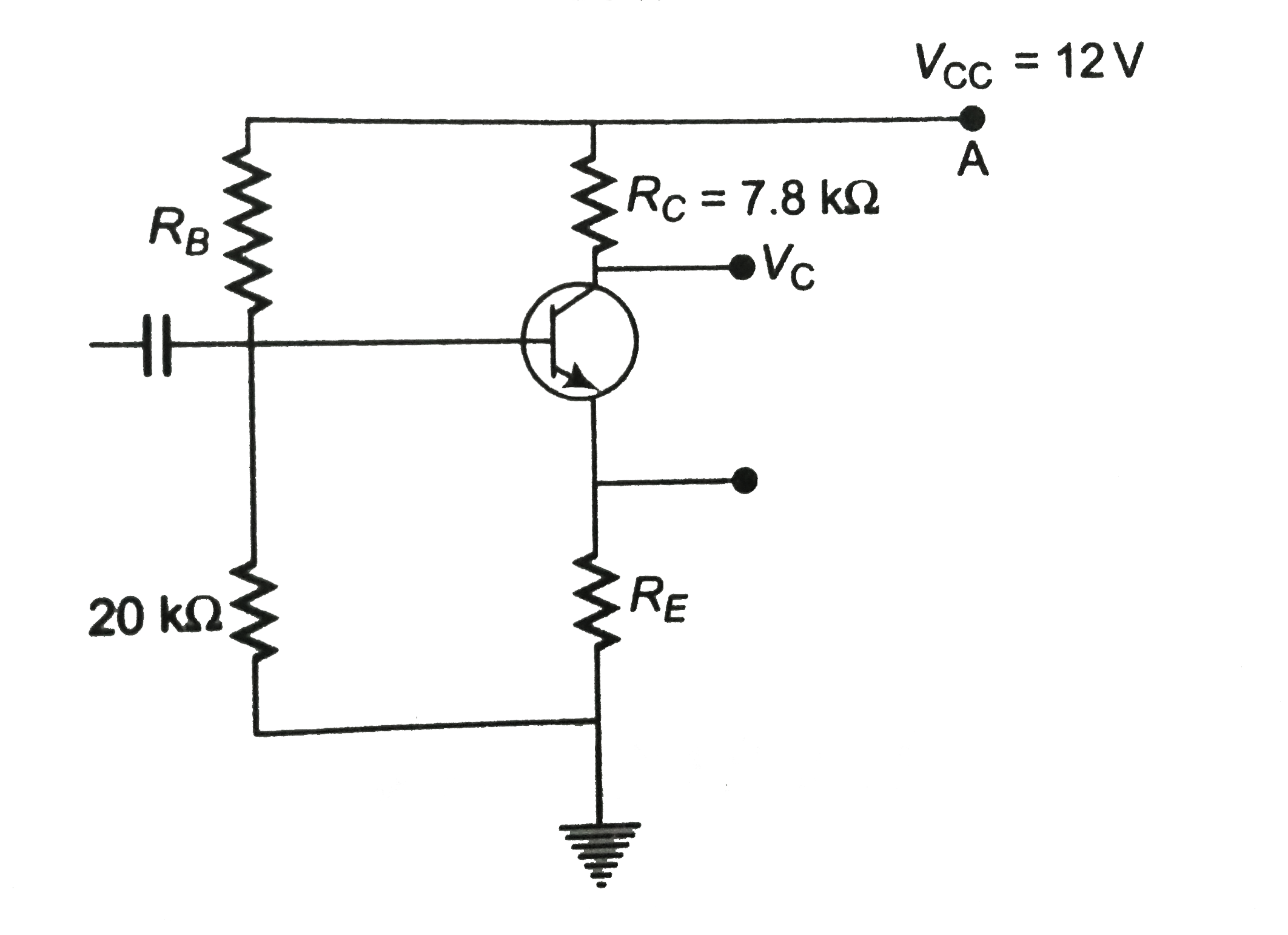
For the transistor circuit shown in figure , evaluate VE,RBandRE. Given IC=1mA,
VCE=3V,VBE=0.5V,VC=12Vandβ=1000
Video Solution
Text Solution
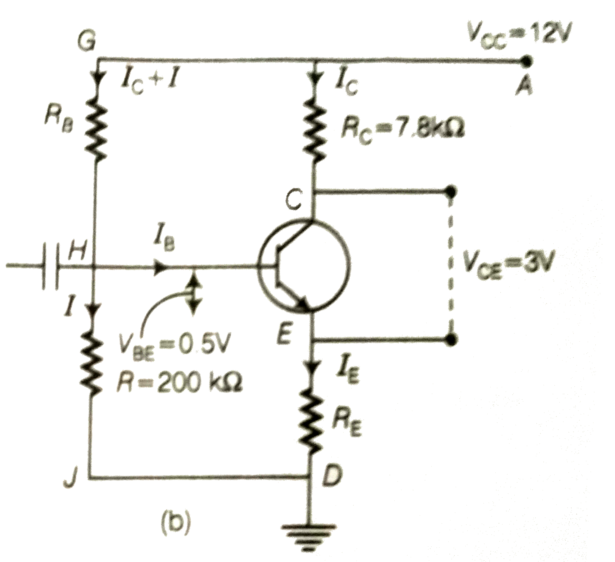
Consider the fig. (b) given here to solve this problem
IC=IE [As base current is very small]
From the figure, IC(RC+RE)+VCE=12
(RE+RC)×1×10⁻³+3=12
RE+RC=9×103=9Ω
RE=9−7.8=1.2kΩ
VE=IE×RE
=1×10−3×1.2×103=1.2V
Voltage VB=VE+VBE=1.2+0.5=1.7V
Current I=VB20×103=1.720×103=0.085mA
Resistance RB=12−1.7ICβ+0.085=10.30.01+0.085[Given,Bη=100]
=108kΩ
|
Updated on:21/07/2023
Topper's Solved these Questions
Similar Questions
Knowledge Check
- Question 1 - Select One
In the circuit shown in figure value of VR is
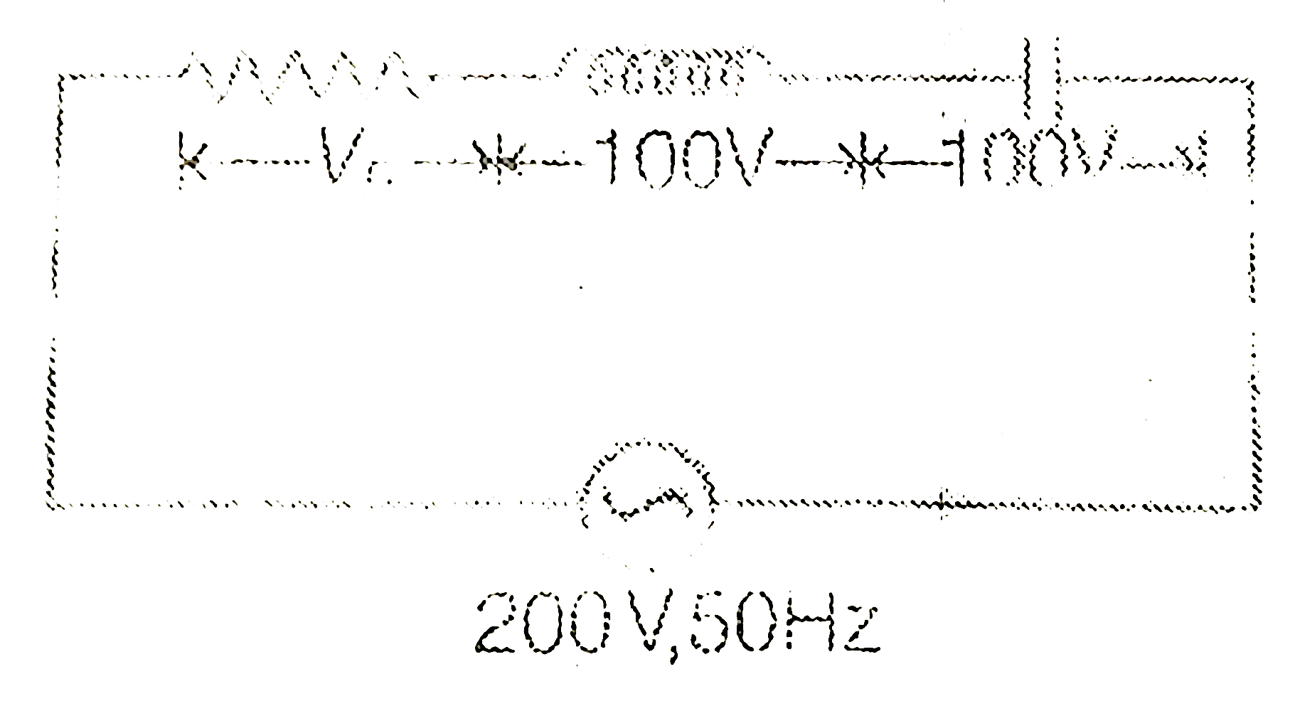 A400VB200VC300VDzero
 - Question 2 - Select One
In the circuit shown in the figure, the ratio of VB as VC is
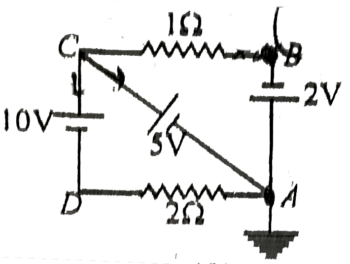 A−2/5B−5/2C1D1/3
 - Question 3 - Select One
Find VP−VQ in the circuit shown in figure.
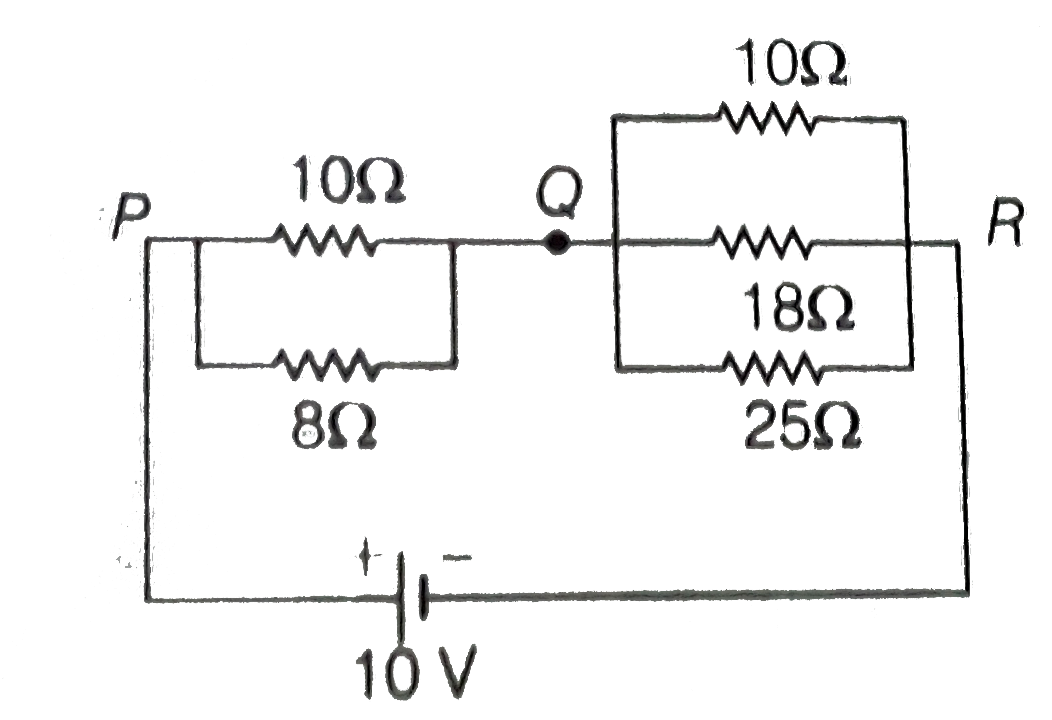 A6.68 VB8 VC4.65 VD7 V
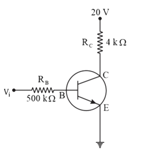
In the circuit shown in the figure, the input voltage Vi is 20V, VBE=0 and VCE=0. The values of IB, IC and β are given by
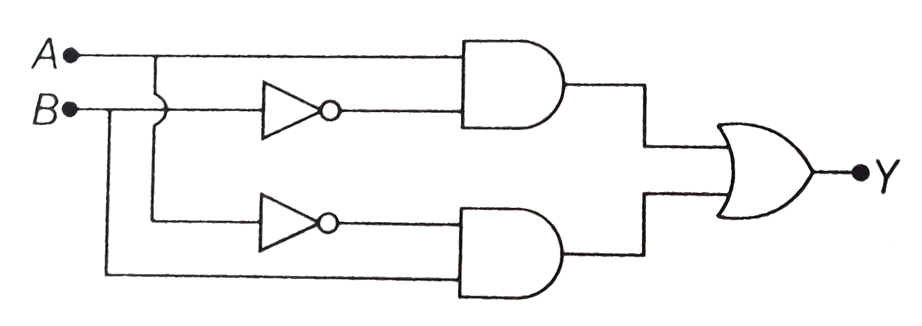 View Solution
In the circuit shown in the figure, the input voltage Vi is 20V,VBE=0 and VCE=0. The values of IB,IC and β are given by:
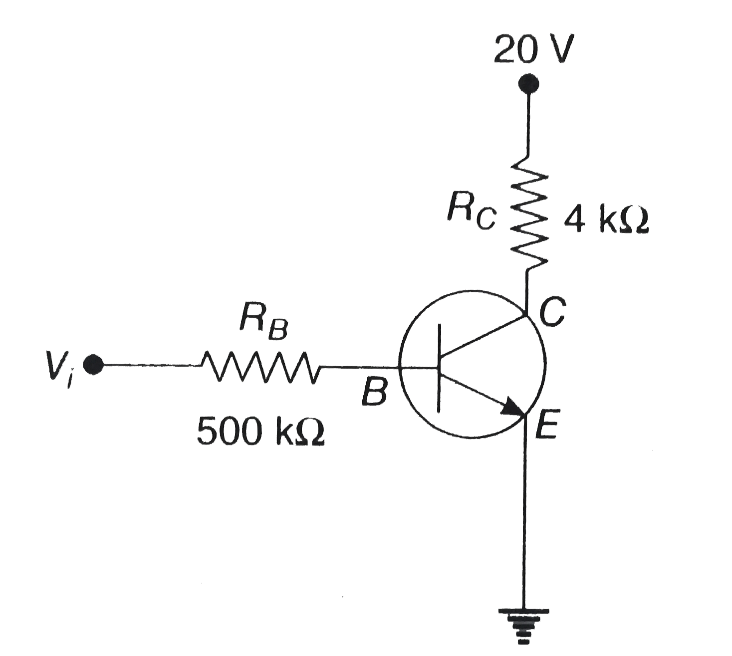 View Solution
In the circuit shown in the figure, the input voltage Vi is 20V,VBE=0 and VCE=0. The values of IB,IC and β are given by:
 View Solution
In the circuit shows in the figure, the input voltage
Vi is 20 V, VBE=0 and VCE=0. The values of lB,lC and β are given by
 View Solution
Passage I
An n-p-n transistor is used as a voltage amplifier in a commoin emitter circuit given
VC=8VIC=4mA
VCE=4V,
(VBE=0.6V,VBB=8V
βDc=200
The value of load resistqacne isView Solution


