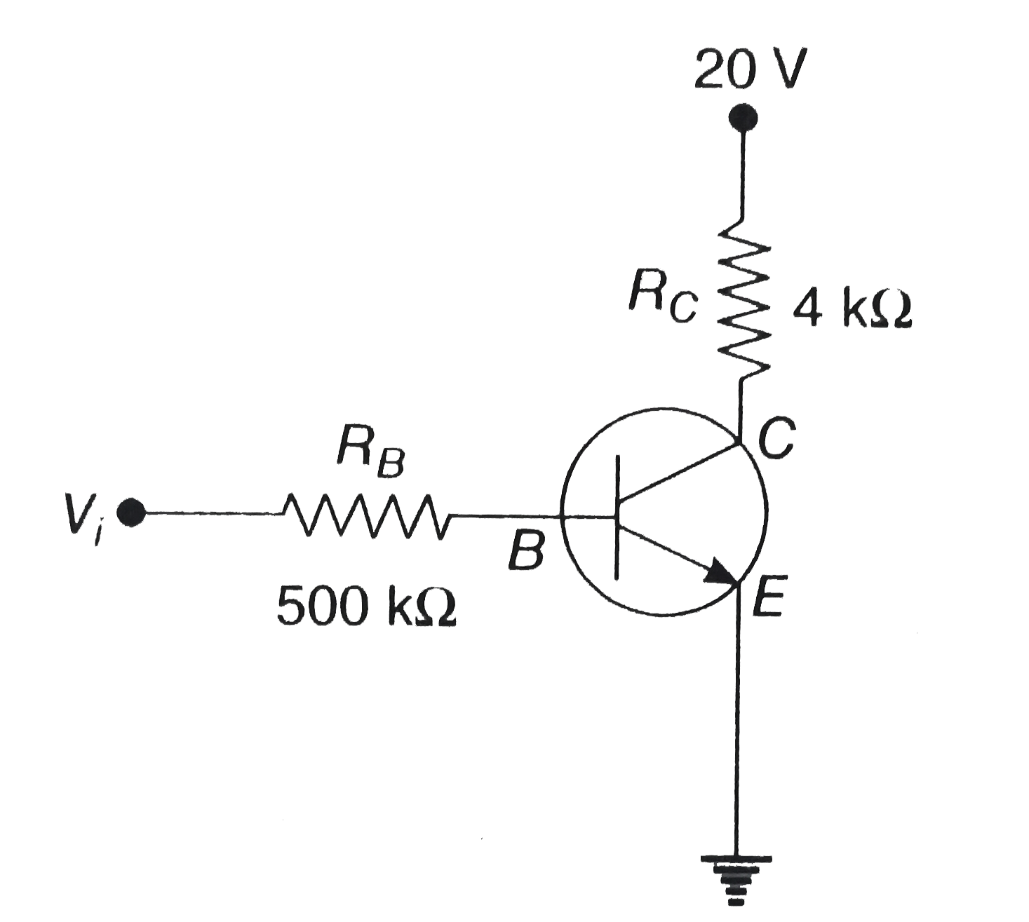
In the circuit shown in Fig. when the input voltage of the base resistance is 10V,Vbe is zero and Vce is also zero. Find the values of I,I and β.
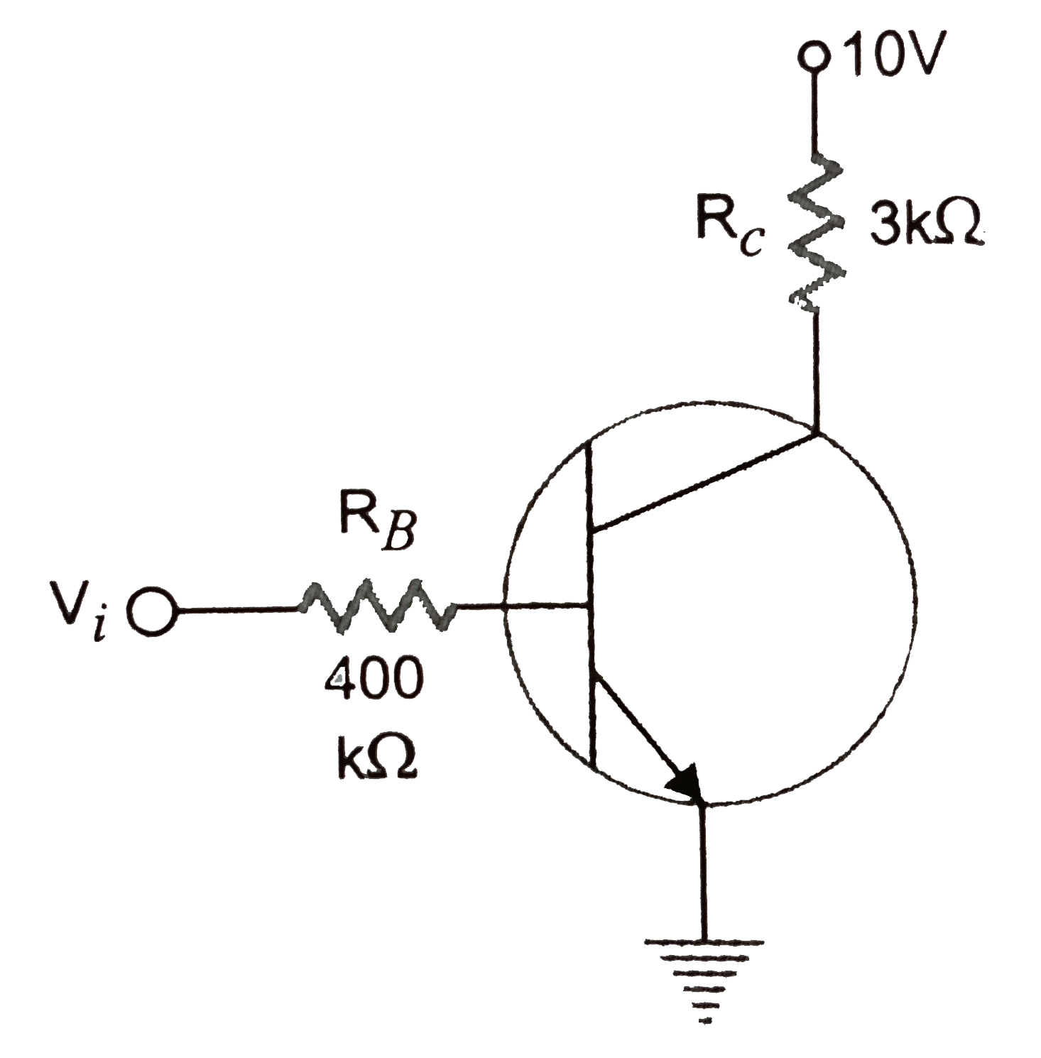
Given, woltage across RB=10V
Resistance RB=400kΩ
VBE=VCE=0RC=3kΩ
IB=Voltage across RBRB
=10400×103=25×10−6A=25μA
Voltage across RC=10V
=3.33×10⁻³A=3.33mA
β=ICIB=3.33×10−325×10−6
=1.33×102=133
Topper's Solved these Questions
Similar Questions
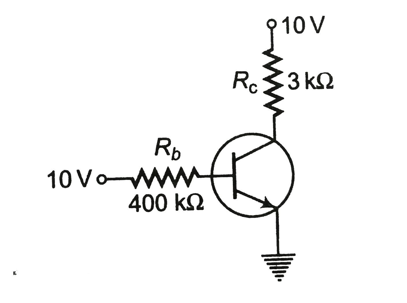
In the circuit shown in Fig.
if we assume that when the input voltage at the base resistance is 5V,VBE is zero and VCE is also zero. What is I,I and beta?
When the input is zero, then I is zero. What would be the output wave form if the input wave form is as shown in Fig.View SolutionIn the circuit shown in figure when the input voltage of the base resistance is 10 V . Find the values of Ib,Icandβ .
 View Solution
Knowledge Check
- Question 1 - Select One
In the circuit shown in figure, when the input voltage of the base resistance is 10 V, Vbe is zero and Vce is also zero. Then
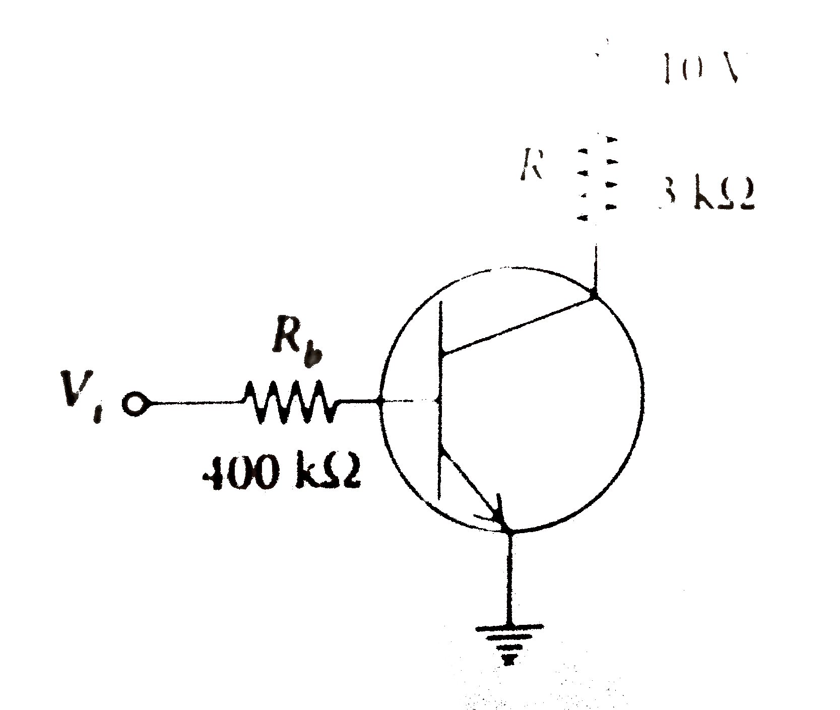 Aβ=110BIb=25μACIc=3.33mADboth (A) and (C )
 - Question 2 - Select One
In the circuit shown in figure, Voltage V0 is
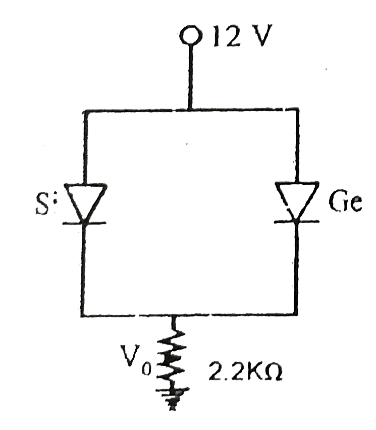 A11.7 voltB11.3 voltC0DNone
 - Question 3 - Select One or More
In the circuit shown in fig. the cell has emf 10V and internal resistance 1Ω
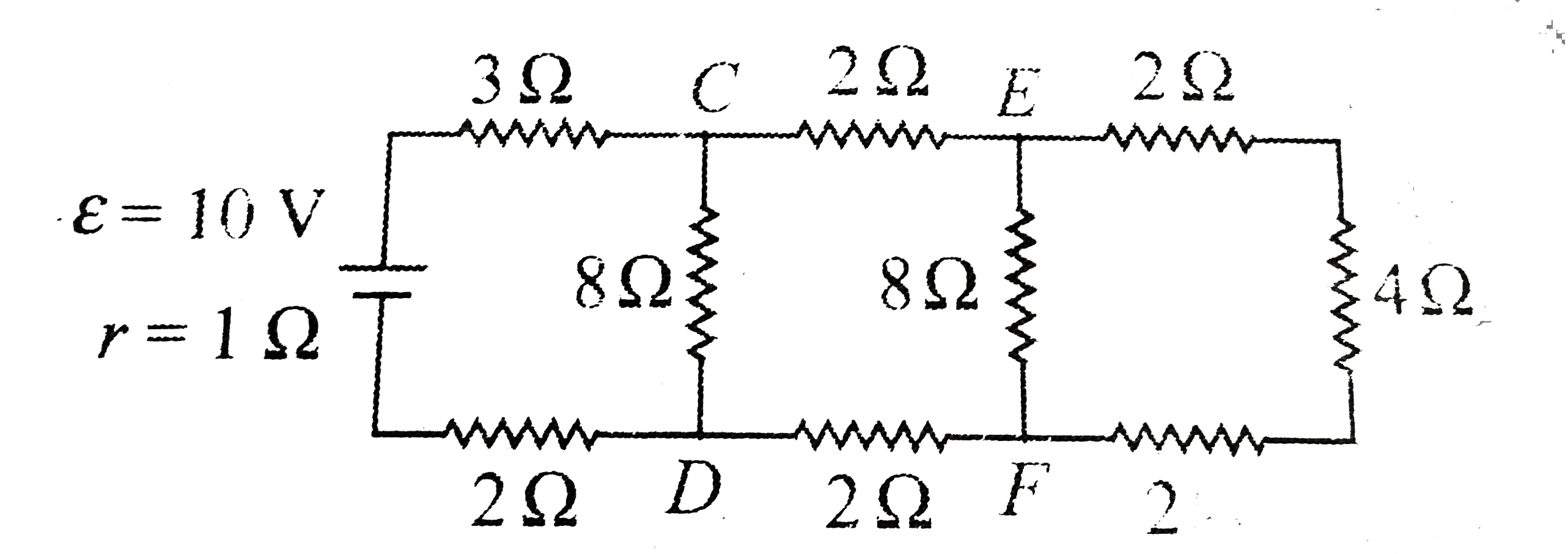 AThe current through the 3Ω resistor is 1A.BThe currents through the 3Ω resistor is 0.5 A.CThe currents through the 4Ω resistor is 0.5 ADThe current through the 4Ω resistor is 0.25 A.
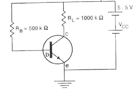
In the accompanying circuit Fig. 5.10, if it is assumed that when that input voltage at the base resistance is 5 V, VBE is zero and VCE is also zero, what are IB,ICandβ ? When the input is zero, IB is zero. What will be the output waveform if the input waveform is as shown in the figure ? What is the practial use of this current ?
 View Solution
In the circuit shown in Fig. 4.63, the terminal voltage of the battery is 6.0 V. Find the current I through the 18Ω resistor.
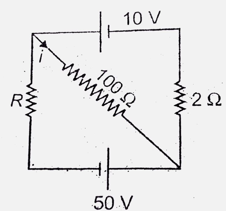
View SolutionIn the circuit shown, the current I will be zero when R is
 View Solution
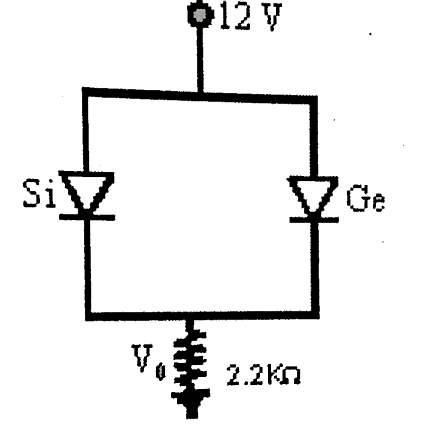
In the circuit shown infigure, voltage V0 is,View SolutionIn the circuit shown in the figure, the input voltage Vi is 20V,VBE=0 and VCE=0. The values of IB,IC and β are given by:
 View Solution

