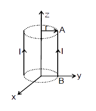
Find the work and power required to move the conductor of length l shown in the fig. one full turn in the anticlockwise direction at a rotational frequency of n revolutions per second if the magnetic field is of magnitude B0 everywhere and points radially outwards from Z-axis. The figure shows that surface traced by the wire AB.

−2πrB0il,−2πrB0iln
4πrB0il,4πrB0iln
2πrB0il,2πrB0iln
−4πrB0il,4πrB0iln
The correct Answer is:A
Step by step video, text & image solution for Find the work and power required to move the conductor of length l shown in the fig. one full turn in the anticlockwise direction at a rotational frequency of n revolutions per second if the magnetic field is of magnitude B_(0) everywhere and points radially outwards from Z-axis. The figure shows that surface traced by the wire AB. by Physics experts to help you in doubts & scoring excellent marks in Class 12 exams.
Topper's Solved these Questions
- BOOK - MOTIONCHAPTER - MAGNETISM EXERCISE - EXERCISE-2 (Level-II)15videos
MAGNETISM
- BOOK - MOTIONCHAPTER - MAGNETISM EXERCISE - EXERCISE-3 (Level-I)46videos
MAGNETISM
- BOOK - MOTIONCHAPTER - MAGNETISM EXERCISE - EXERCISE-150videos
MAGNETISM
- BOOK - MOTIONCHAPTER - LOGIC GATESEXERCISE - EXERCISE - 210videos
LOGIC GATES
- BOOK - MOTIONCHAPTER - MAGNETISM -1EXERCISE - Exercise - 3 SECTION -A56videos
MAGNETISM -1
Similar Questions
If the work required to move the conductor shown in figure, one full turn in the positive direction at a rotational frequency N revolutions per minute, if →B=B0ˆar(B0 is positive constant and ˆar is a unit vector in radial direciton ), is yπrB0il. Then y is .
 View Solution
There are two co-axial non conducting cylinders of radii a and b(>a). Length of each cylinder is L(>>b) and their curved surfaces have uniform surface charge densities of–σ (on cylinder of radius a) and +σ (on cylinder of radius b). The two cylinders are made to rotate with same angular velocity ω as shown in the figure. The charge distribution does not change due to rotation. Find the electric field (E) and magnetic field (B) at a point (P) which is at a distance r from the axis such that (a) 0<r<a (b) a<r<b (c) r>b. Assume that point P is close to perpendicular bisector of the length of the cylinders
 View Solution
Knowledge Check
- Question 1 - Select One
A wire frame in the form of a part of circle ( sector ) of radius 1 and resistance R is free to rotate about on axis passing through O and perpendicular to plane of paper as shown in the figure. The angle of the sector is π4 and it is rotating with constant angular velocity ω as shown. Above line PQ uniform magnetic field of magnitude B exists in the direction perpendicular to plane of paper. In region I field is outward while in region II, field is inward.

Based on above information, answer the following questions :
The thermal energy dissipated in wire frame when it moves from region I to region II, isAB2ωπpl416RBB2ωπpl44RC3B2ωpl48RD3B2ωpl416R - Question 2 - Select One
A conducting bar of mass m and length l moves on two frictionless parallel rails in the presence of a constant uniform magnetic field of magnitude B directed into the page as shown in the figure . The bar is given an initial velocity v0 towards the right at t = 0. Then the
 AInduced current in the circuit is in the clockwise directionBVelocity of the bar decreases linearly with timeCDistance the bar travels before it comes to a complete stop is proportional to RDPower generated across the resistance is proportional to l.
 - Question 3 - Select One
A wire frame in the form of a part of circle ( sector ) of radius 1 and resistance R is free to rotate about on axis passing through O and perpendicular to plane of paper as shown in the figure. The angle of the sector is π4 and it is rotating with constant angular velocity ω as shown. Above line PQ uniform magnetic field of magnitude B exists in the direction perpendicular to plane of paper. In region I field is outward while in region II, field is inward.

Based on above information, answer the following questions :
Average power produced in wire framce isA3B2ωpl416RBB2ω2l416RCB2ω2l48RD3B2ω2l48R
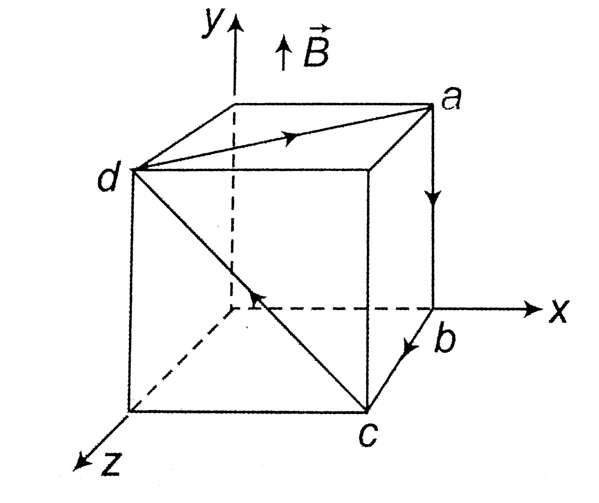
In the given figure, the cube is length l on each side. Four straight segments of wire ab,bc,cd and da form a closed loop that carries a current I=i0 in the direction shown. A uniform magnetic field of magnitude B=B0 is in the positive y direction. Determine the torque on the loop
 View Solution
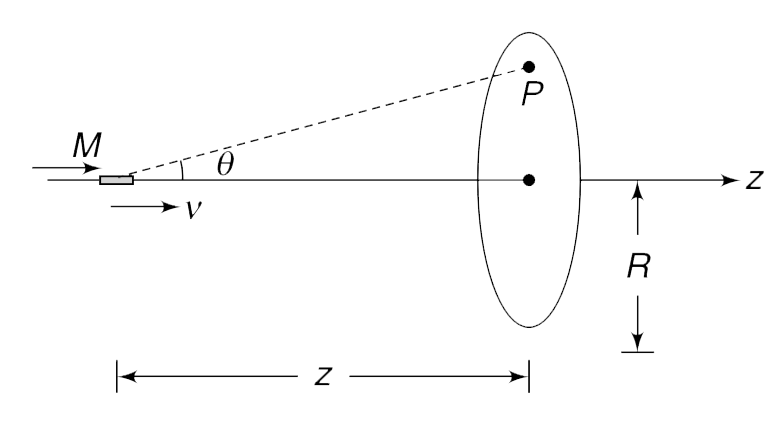
A short bar magnet having magnetic dipole moment M is moving along the axis of a fixed conducting (non magnetic) ring of radius R. The axis of the ring is along z direction.

(a) Write the z component of magnetic field due to the magnetic dipole at a point P in the plane of the ring, at the instant the magnet is at a distance z from the centre of the ring. Position of point P can be defined in terms of angle θ as shown.
(b) Write the magnetic flux through the ring due to the magnetic field produced by the magnet as a function of z.
(c) Write the magnitude of emf induced in the ring at the instant shown if speed of the magnet at the moment is v.View SolutionA charge of 1 coul. is placed at one end of a non-conducting rod of length 0.6m. the rod is rotated in a vertical plane about a horizontal axis passing through the other end of the rod with angular frequency 104πradian/sec. Find the magnetic field at a point on the axis ofrotation at a distance of 0.8 from the centre of the path. Now half of the charge is removed from one end and placed on the other end. The rod is rotated in a vertical plane about horizontal axis passing through the mid-point of the rod with the same angnlar frequency. Calculate the magnetic field at a point on the axis at a distance of 0.4m form the centre of the rod.
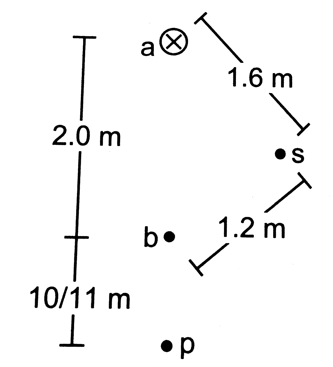
View SolutionTwo long, straight wires a and b are 2⋅0 m apart,
perpendicular to the plane of the paper as shown in figure
. The wire a carries a current of 9⋅6A directed
into the plane of the figure,The magnetic field at the
point P at a distance of 10/11 m from the wire b is zero.
Find (a) the magnitude and direction of the current in b,
(b) the magnitude of the magnetic field B at the point s
and (c) the force per unit length on the wire b.
 View Solution
A conducting rod of length l is higed at point O. It is free to rotate in a vertical plane. There exists a uniform magnetic field →B in horizontal direction. The rod is released from the position shown in figure. Potential difference between the two ends of the rod is proportional to
View Solution

