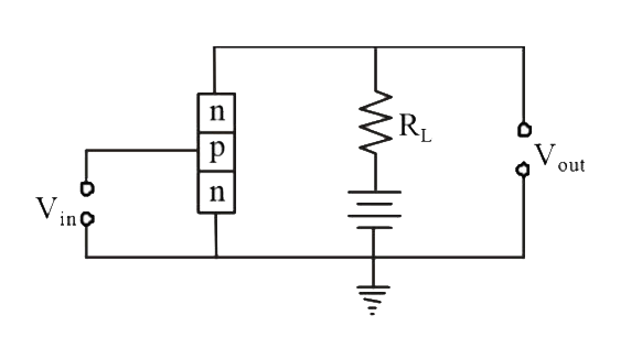
An P−N−P transistor circuit is arranged as shown. It is a
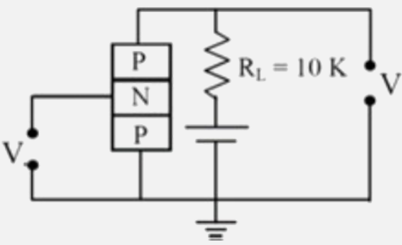
common base amplifier circuit
common - emitter amplifier circuit
common - collector circuit
none
The correct Answer is:C
Step by step video & image solution for An P-N-P transistor circuit is arranged as shown. It is a by Physics experts to help you in doubts & scoring excellent marks in Class 12 exams.
Updated on:21/07/2023Topper's Solved these Questions
Similar Questions
Knowledge Check
An NPN-transistor circuit is arranged as shown in figure. It is
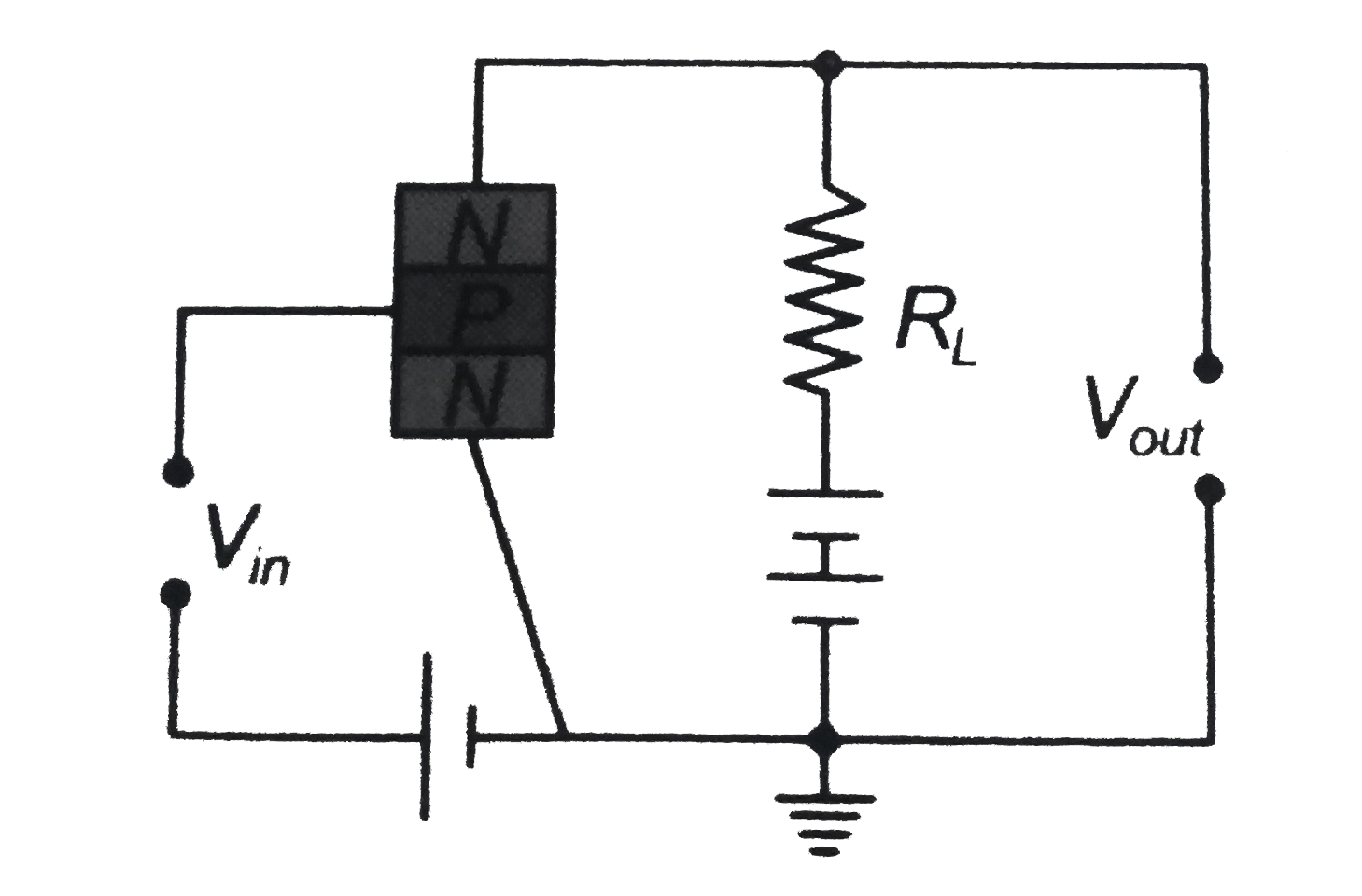 AA common base amplifier circuitBA common emitter amplifier circuitCA common collector amplifier circuitDNeither of the above
In an n-p-n transistor
Athe emitter has higher degree of doping compared to that of the collectorBthe collector has higher degree of doping compared to that of the emitterCboth the emitter and collector have same degree of dopingDthe base region is most heavily doped.A n−p−n transistor conducts when
Aboth collector and emitter are positive when respect to the baseBcollector is positive and emitter is negative with respect to the baseCcollector is positive and emitter is at same potential as the baseDboth collector and emitter are negative with respect to the base
In the p-n-p transistor circuit shown in Fig.
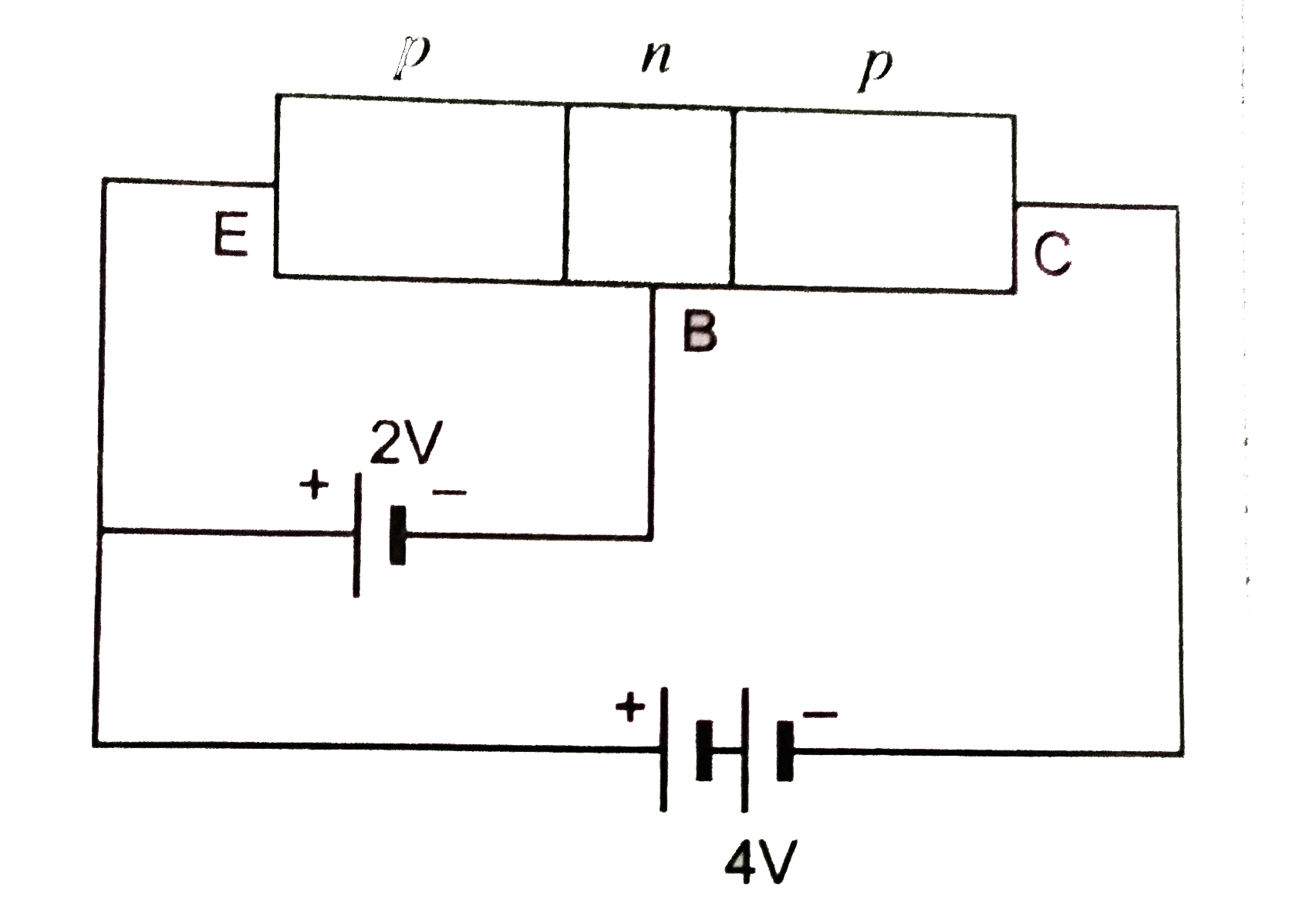
What is the potential difference between base and collector?
What is the nature of biasing between emitter base junction and collector-base junction?
View SolutionIn an n-p-n transistor circuit, the collector current is 20 mA. If 90 % of electron emitted reach the collector :-
View SolutionIn n-p-n transistor circuit, the collector current is 20 mA. If 90% of the electrons emitted reache the collector, then the
View SolutionIn an n-p-n transistor circuit, the collector current ia 10 mA. If 90% of the electrons emitted reach the collector.
View SolutionWhen N-P-N transistor is used as an amplifier-
View Solution

