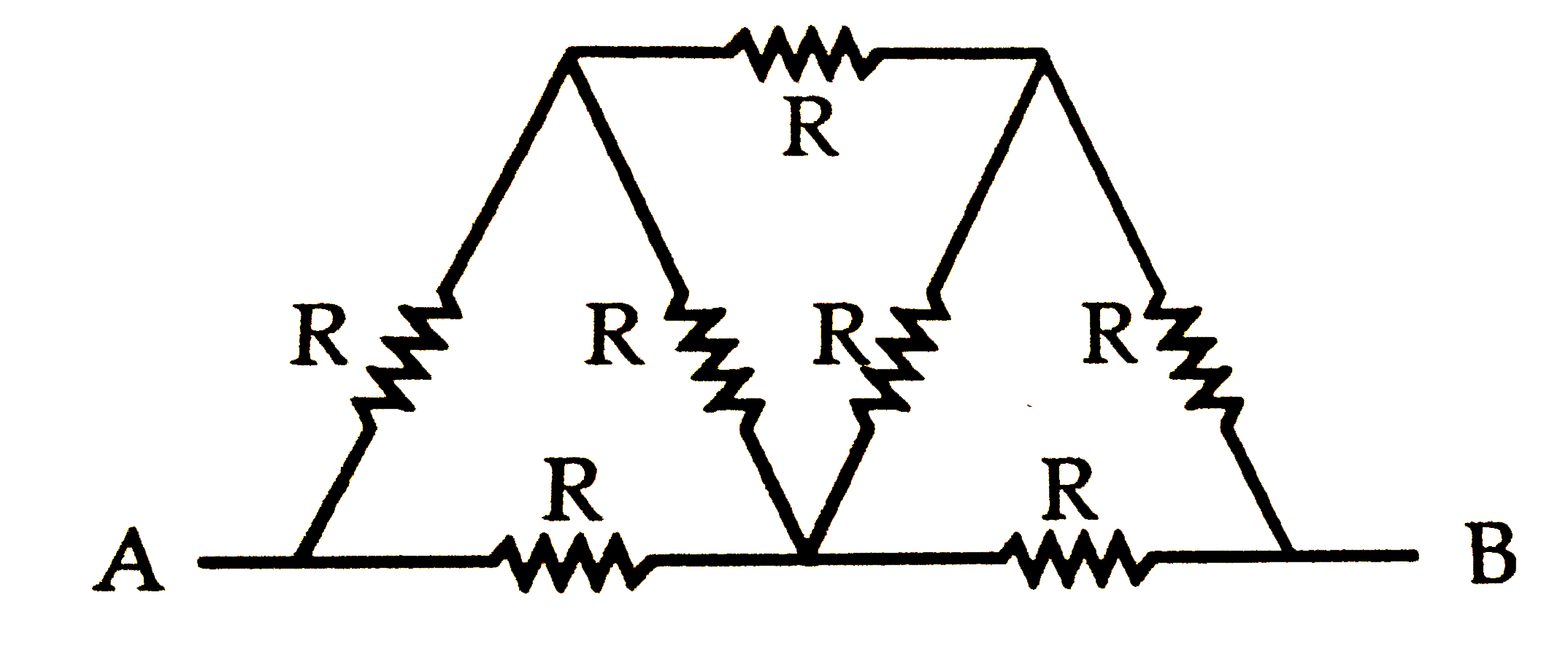
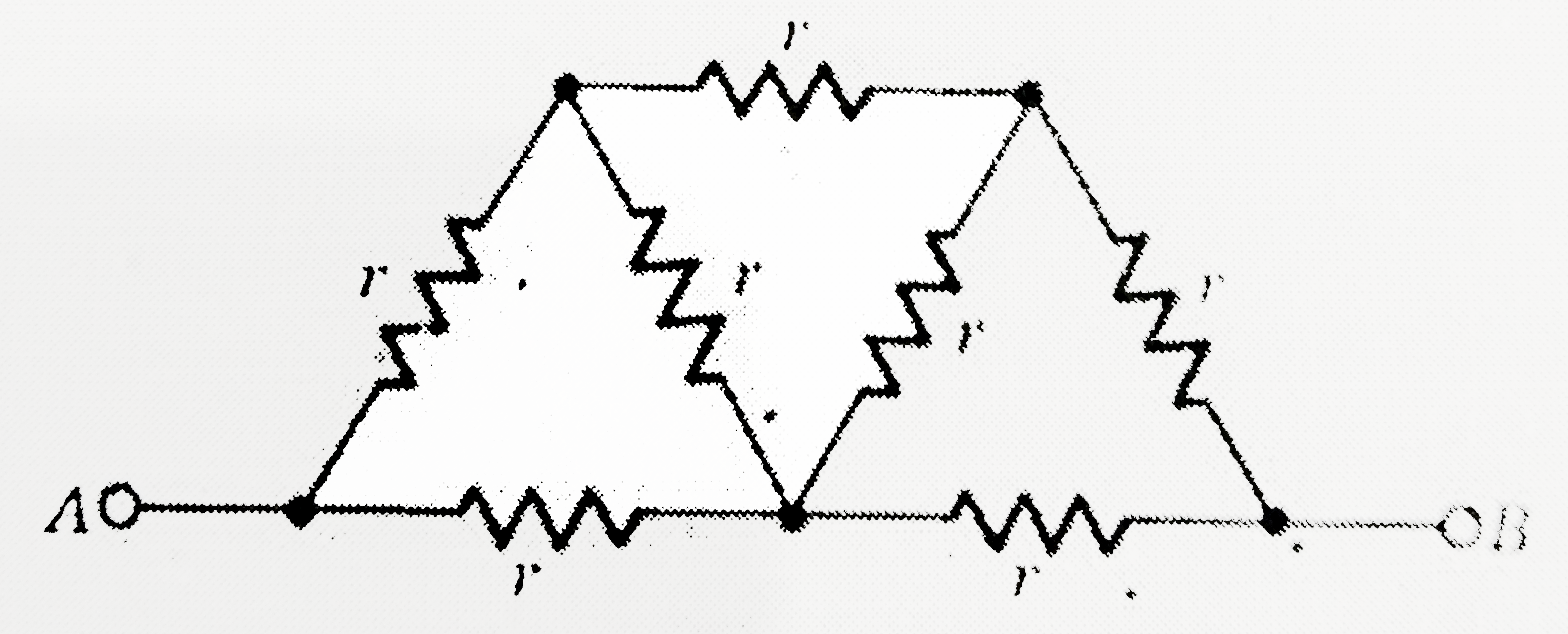
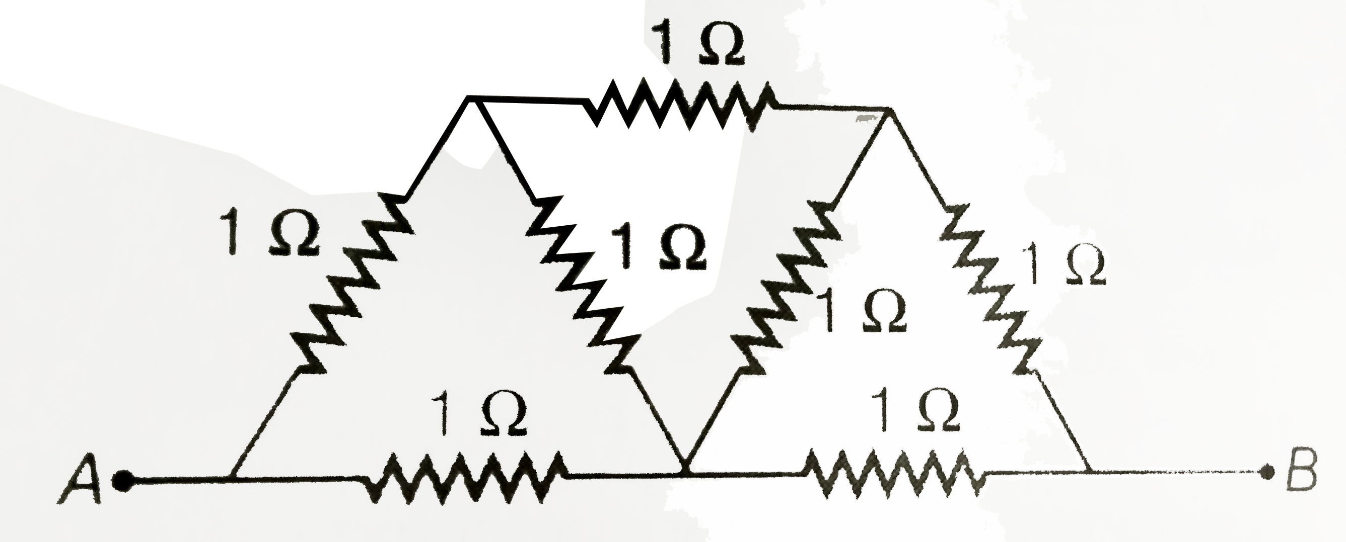
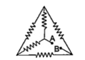
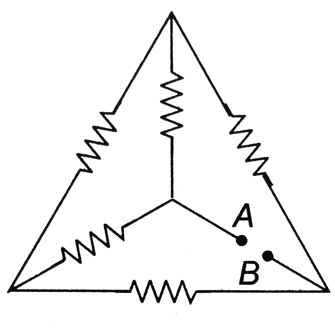
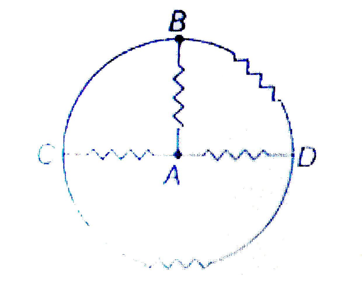
In the network shown in figure each resistance is 1Ω . The effective resistance between A and B is
43Ω
32Ω
7Ω
87Ω
The correct Answer is:D
Step by step video & image solution for In the network shown in figure each resistance is 1Omega . The effective resistance between A and B is by Physics experts to help you in doubts & scoring excellent marks in Class 12 exams.
Updated on:21/07/2023Topper's Solved these Questions
Similar Questions
Knowledge Check
In the network shown in figure, each resistance is R. The equvalent resistance between points A and B is
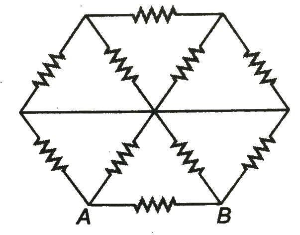 A2011RB1911RC815RDR2
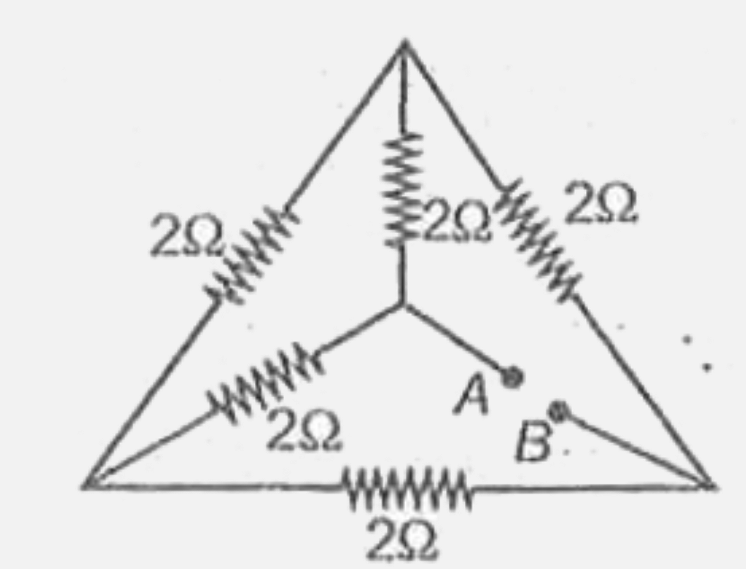
In the network shown in the figure, each of the resistances is equal to 2Ω . The resistances between the points A and B is
 A4ΩB3ΩC2ΩD1Ω
In the network shown in the figure, each of the resistance is equal to 2Ω. The resistance between the points A and B is
 A1ΩB4ΩC3ΩD2Ω
Shown in the figure is an infinite network of resistors each of resistance 1Ω . The effective resistance in between A and B is

View SolutionIn the network shown in the figure, each of the resistance is equal to 2Ω . The resistance between the point A and B is
View Solutionln the network shown in the figure, each of the resistances is equal to 2Ω. The resistances between the points A and B is
View SolutionIn the circuit shown in figure, each resistance is Net resistance between points A and B is
View SolutionEach resistor shown in figure is an infinite network of resistance1Ω. The effective resistance Between points A and B is

View Solution

