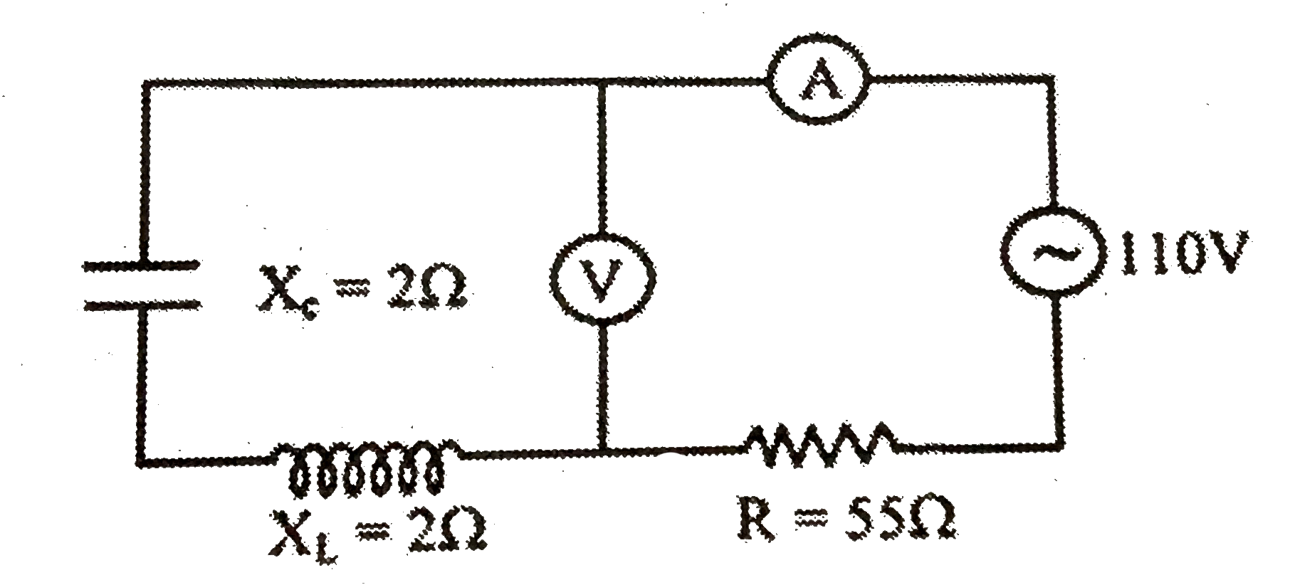
The reading of the ammeter and voltmeter are ( Both the instruments are ac meters and measures rms value) -
2A , 110 V
2 A, 0 V
2V , 55 V
1 A, 0 V
The correct Answer is:B
To solve the problem, we need to analyze the given AC circuit and determine the readings of the ammeter and voltmeter. Here’s a step-by-step breakdown of the solution:
Step 1: Identify the Circuit Components
We have an AC circuit with:
- Resistance (R) = 55 ohms
- Inductive reactance (XL) = 2 ohms
- Capacitive reactance (XC) = 2 ohms
Step 2: Determine the Condition of the Circuit
Since XL = XC, the circuit is in resonance. In a resonant LCR circuit, the total impedance (Z) is equal to the resistance (R) because the inductive and capacitive reactances cancel each other out.
Step 3: Calculate the Impedance (Z)
Using the formula for impedance in a series LCR circuit:
Z=√R2+(XL−XC)2
Since XL = XC, the equation simplifies to:
Z=√R2=R
Thus,
Z=55ohms
Step 4: Calculate the RMS Current (Irms)
The RMS voltage (Vrms) provided is 110 volts. The relationship between voltage, current, and impedance is given by Ohm's law:
Irms=VrmsZ
Substituting the known values:
Irms=110V55ohms=2A
Step 5: Determine the Voltmeter Reading
In a resonant circuit, the voltmeter measures the voltage across the inductor and capacitor, which cancel each other out, resulting in:
VL=VC
Thus, the voltmeter reading is:
Vrms=0V
Final Readings
- Ammeter Reading (Irms): 2 A
- Voltmeter Reading (Vrms): 0 V
Summary of Results
The ammeter reads 2 A, and the voltmeter reads 0 V.
---
We have an AC circuit with:
- Resistance (R) = 55 ohms
- Inductive reactance (XL) = 2 ohms
- Capacitive reactance (XC) = 2 ohms
Since XL = XC, the circuit is in resonance. In a resonant LCR circuit, the total impedance (Z) is equal to the resistance (R) because the inductive and capacitive reactances cancel each other out.
Using the formula for impedance in a series LCR circuit:
Z=√R2+(XL−XC)2
Since XL = XC, the equation simplifies to:
Z=√R2=R
Thus,
Z=55ohms
The RMS voltage (Vrms) provided is 110 volts. The relationship between voltage, current, and impedance is given by Ohm's law:
Irms=VrmsZ
Substituting the known values:
Irms=110V55ohms=2A
In a resonant circuit, the voltmeter measures the voltage across the inductor and capacitor, which cancel each other out, resulting in:
VL=VC
Thus, the voltmeter reading is:
Vrms=0V
- Ammeter Reading (Irms): 2 A
- Voltmeter Reading (Vrms): 0 V
The ammeter reads 2 A, and the voltmeter reads 0 V.
Topper's Solved these Questions
Similar Questions
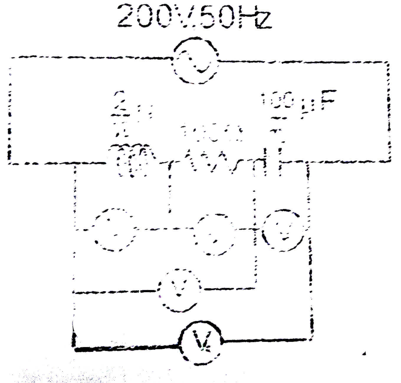
In the circuit shown in the figure, find:
(a) the reactance of the circuit
(b) impedance of the circuit
(c )the current
(d) readings of the ideal AC voltmeters(these are hot wire instruments and read rms values)
 View Solution
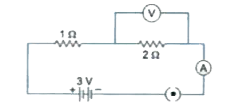
What would be the reading of ammeter and voltmeter in the given circuit?
 View Solution
Knowledge Check
- Question 1 - Select One
The reading of the ammeter and voltmeters are (Both the instruments are ac meters and measures rms value)-
 A2A,110VB2A,0VC2A,55VD1A,0V
 - Question 2 - Select One
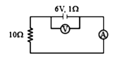
Find the readings of the ammeter (A) and voltmeter (V):
 A6 A, 60 VB0.6A, 6VC6A, 6VD611A,6011V
 - Question 3 - Select One
The reading of ammeter and voltmeter in the following circuit are respectively
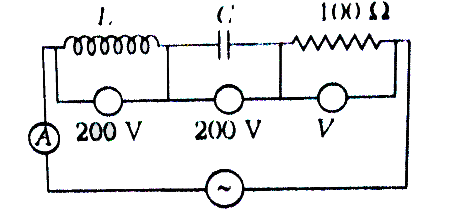 A2 A , 200 VB1.5 A , 100 VC2.7 A, 220 VD22 A, 220 V
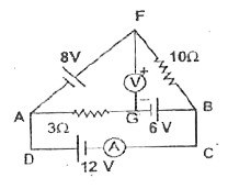
Find the reading of ammeter A and voltmeter V shown in the figure assuming the instruments to be ideal
 View Solution
For the AC circuit shown in the figure the reading' of ammeter and voltmeter are 5A and 50√5V, respectively. The rms value of (AC) source (in volt) is
'(##CEN_KSR_PHY_JEE_C24_E01_029_Q14##)'View SolutionIn the circuit shown the reading of ammeter and voltmeter are 4A and 20V respectively. The meters are non ideal, then R ia
 View Solution
Assertion : In the circuit shown in figure ammeter and voltmeter are non-ideal. Why positions of ammeter and voltmeter are changed, reading of ammeter will increase while of voltmeter will decrease.
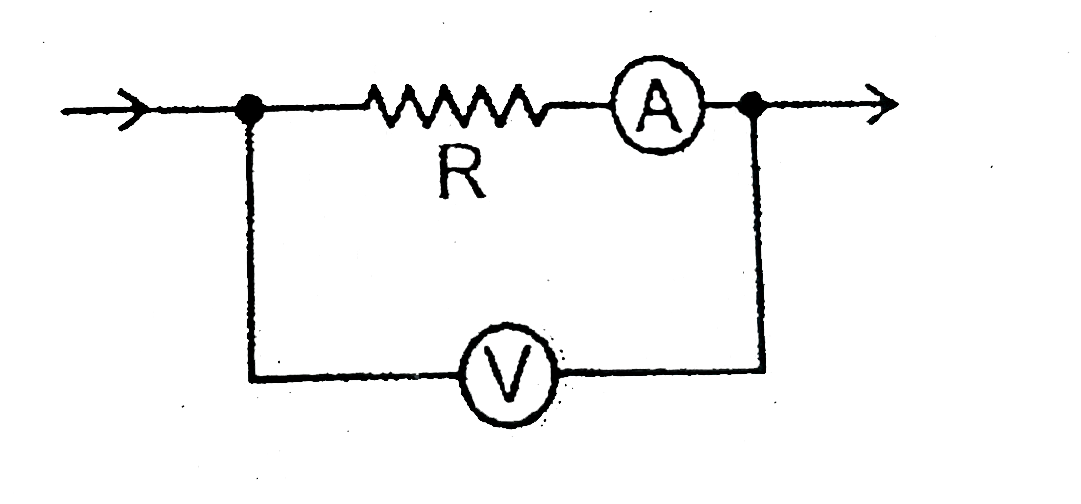
Reason : Resistance of an ideal ammeter is zero while that of an ideal voltmeter is infinite.View SolutionIn the, Ohm's law experiment ot find resistance of unknown resistor R, the arrangement is as shown. The resistance measured is given by Rmeasured=ViV= voltage reading of voltmeter. i=current reading of ammeter. The ammeters and the voltmeter used are not ideal, and have resistance RA and RV respectively. For arrangement shown, the meausred resistance is
 View Solution

